EP0270990B1 - Regenerierbares Abgasfilter für Verbrennungsmotoren - Google Patents
Regenerierbares Abgasfilter für Verbrennungsmotoren Download PDFInfo
- Publication number
- EP0270990B1 EP0270990B1 EP87117828A EP87117828A EP0270990B1 EP 0270990 B1 EP0270990 B1 EP 0270990B1 EP 87117828 A EP87117828 A EP 87117828A EP 87117828 A EP87117828 A EP 87117828A EP 0270990 B1 EP0270990 B1 EP 0270990B1
- Authority
- EP
- European Patent Office
- Prior art keywords
- filter
- conductive
- fabric
- threads
- filtering
- Prior art date
- Legal status (The legal status is an assumption and is not a legal conclusion. Google has not performed a legal analysis and makes no representation as to the accuracy of the status listed.)
- Expired - Lifetime
Links
Images

Classifications
-
- F—MECHANICAL ENGINEERING; LIGHTING; HEATING; WEAPONS; BLASTING
- F01—MACHINES OR ENGINES IN GENERAL; ENGINE PLANTS IN GENERAL; STEAM ENGINES
- F01N—GAS-FLOW SILENCERS OR EXHAUST APPARATUS FOR MACHINES OR ENGINES IN GENERAL; GAS-FLOW SILENCERS OR EXHAUST APPARATUS FOR INTERNAL-COMBUSTION ENGINES
- F01N3/00—Exhaust or silencing apparatus having means for purifying, rendering innocuous, or otherwise treating exhaust
- F01N3/02—Exhaust or silencing apparatus having means for purifying, rendering innocuous, or otherwise treating exhaust for cooling, or for removing solid constituents of, exhaust
- F01N3/021—Exhaust or silencing apparatus having means for purifying, rendering innocuous, or otherwise treating exhaust for cooling, or for removing solid constituents of, exhaust by means of filters
- F01N3/0217—Exhaust or silencing apparatus having means for purifying, rendering innocuous, or otherwise treating exhaust for cooling, or for removing solid constituents of, exhaust by means of filters the filtering elements having the form of hollow cylindrical bodies
-
- F—MECHANICAL ENGINEERING; LIGHTING; HEATING; WEAPONS; BLASTING
- F01—MACHINES OR ENGINES IN GENERAL; ENGINE PLANTS IN GENERAL; STEAM ENGINES
- F01N—GAS-FLOW SILENCERS OR EXHAUST APPARATUS FOR MACHINES OR ENGINES IN GENERAL; GAS-FLOW SILENCERS OR EXHAUST APPARATUS FOR INTERNAL-COMBUSTION ENGINES
- F01N3/00—Exhaust or silencing apparatus having means for purifying, rendering innocuous, or otherwise treating exhaust
- F01N3/02—Exhaust or silencing apparatus having means for purifying, rendering innocuous, or otherwise treating exhaust for cooling, or for removing solid constituents of, exhaust
- F01N3/021—Exhaust or silencing apparatus having means for purifying, rendering innocuous, or otherwise treating exhaust for cooling, or for removing solid constituents of, exhaust by means of filters
- F01N3/0218—Exhaust or silencing apparatus having means for purifying, rendering innocuous, or otherwise treating exhaust for cooling, or for removing solid constituents of, exhaust by means of filters the filtering elements being made from spirally-wound filtering material
-
- F—MECHANICAL ENGINEERING; LIGHTING; HEATING; WEAPONS; BLASTING
- F01—MACHINES OR ENGINES IN GENERAL; ENGINE PLANTS IN GENERAL; STEAM ENGINES
- F01N—GAS-FLOW SILENCERS OR EXHAUST APPARATUS FOR MACHINES OR ENGINES IN GENERAL; GAS-FLOW SILENCERS OR EXHAUST APPARATUS FOR INTERNAL-COMBUSTION ENGINES
- F01N3/00—Exhaust or silencing apparatus having means for purifying, rendering innocuous, or otherwise treating exhaust
- F01N3/02—Exhaust or silencing apparatus having means for purifying, rendering innocuous, or otherwise treating exhaust for cooling, or for removing solid constituents of, exhaust
- F01N3/021—Exhaust or silencing apparatus having means for purifying, rendering innocuous, or otherwise treating exhaust for cooling, or for removing solid constituents of, exhaust by means of filters
- F01N3/022—Exhaust or silencing apparatus having means for purifying, rendering innocuous, or otherwise treating exhaust for cooling, or for removing solid constituents of, exhaust by means of filters characterised by specially adapted filtering structure, e.g. honeycomb, mesh or fibrous
-
- F—MECHANICAL ENGINEERING; LIGHTING; HEATING; WEAPONS; BLASTING
- F01—MACHINES OR ENGINES IN GENERAL; ENGINE PLANTS IN GENERAL; STEAM ENGINES
- F01N—GAS-FLOW SILENCERS OR EXHAUST APPARATUS FOR MACHINES OR ENGINES IN GENERAL; GAS-FLOW SILENCERS OR EXHAUST APPARATUS FOR INTERNAL-COMBUSTION ENGINES
- F01N3/00—Exhaust or silencing apparatus having means for purifying, rendering innocuous, or otherwise treating exhaust
- F01N3/02—Exhaust or silencing apparatus having means for purifying, rendering innocuous, or otherwise treating exhaust for cooling, or for removing solid constituents of, exhaust
- F01N3/021—Exhaust or silencing apparatus having means for purifying, rendering innocuous, or otherwise treating exhaust for cooling, or for removing solid constituents of, exhaust by means of filters
- F01N3/022—Exhaust or silencing apparatus having means for purifying, rendering innocuous, or otherwise treating exhaust for cooling, or for removing solid constituents of, exhaust by means of filters characterised by specially adapted filtering structure, e.g. honeycomb, mesh or fibrous
- F01N3/0222—Exhaust or silencing apparatus having means for purifying, rendering innocuous, or otherwise treating exhaust for cooling, or for removing solid constituents of, exhaust by means of filters characterised by specially adapted filtering structure, e.g. honeycomb, mesh or fibrous the structure being monolithic, e.g. honeycombs
-
- F—MECHANICAL ENGINEERING; LIGHTING; HEATING; WEAPONS; BLASTING
- F01—MACHINES OR ENGINES IN GENERAL; ENGINE PLANTS IN GENERAL; STEAM ENGINES
- F01N—GAS-FLOW SILENCERS OR EXHAUST APPARATUS FOR MACHINES OR ENGINES IN GENERAL; GAS-FLOW SILENCERS OR EXHAUST APPARATUS FOR INTERNAL-COMBUSTION ENGINES
- F01N3/00—Exhaust or silencing apparatus having means for purifying, rendering innocuous, or otherwise treating exhaust
- F01N3/02—Exhaust or silencing apparatus having means for purifying, rendering innocuous, or otherwise treating exhaust for cooling, or for removing solid constituents of, exhaust
- F01N3/021—Exhaust or silencing apparatus having means for purifying, rendering innocuous, or otherwise treating exhaust for cooling, or for removing solid constituents of, exhaust by means of filters
- F01N3/023—Exhaust or silencing apparatus having means for purifying, rendering innocuous, or otherwise treating exhaust for cooling, or for removing solid constituents of, exhaust by means of filters using means for regenerating the filters, e.g. by burning trapped particles
- F01N3/027—Exhaust or silencing apparatus having means for purifying, rendering innocuous, or otherwise treating exhaust for cooling, or for removing solid constituents of, exhaust by means of filters using means for regenerating the filters, e.g. by burning trapped particles using electric or magnetic heating means
-
- F—MECHANICAL ENGINEERING; LIGHTING; HEATING; WEAPONS; BLASTING
- F01—MACHINES OR ENGINES IN GENERAL; ENGINE PLANTS IN GENERAL; STEAM ENGINES
- F01N—GAS-FLOW SILENCERS OR EXHAUST APPARATUS FOR MACHINES OR ENGINES IN GENERAL; GAS-FLOW SILENCERS OR EXHAUST APPARATUS FOR INTERNAL-COMBUSTION ENGINES
- F01N2330/00—Structure of catalyst support or particle filter
- F01N2330/10—Fibrous material, e.g. mineral or metallic wool
-
- F—MECHANICAL ENGINEERING; LIGHTING; HEATING; WEAPONS; BLASTING
- F01—MACHINES OR ENGINES IN GENERAL; ENGINE PLANTS IN GENERAL; STEAM ENGINES
- F01N—GAS-FLOW SILENCERS OR EXHAUST APPARATUS FOR MACHINES OR ENGINES IN GENERAL; GAS-FLOW SILENCERS OR EXHAUST APPARATUS FOR INTERNAL-COMBUSTION ENGINES
- F01N2370/00—Selection of materials for exhaust purification
- F01N2370/22—Selection of materials for exhaust purification used in non-catalytic purification apparatus
Definitions
- This invention relates to a regenerable filter in the exhaust gases of an internal-combustion engine.
- this invention relates to a filter suited to be placed into an exhaust pipe of an internal-combustion engine, comprising a filtering member suited to intercept the residual combustion products contained in the exhaust gases and further comprising means suited to produce the combustion of said residues.
- Filters are known in which said means suited to produce the combustion of the residues are of the kind that uses a catalyst for the starting of the combustion at low temperatures, or of the kind that heats the exhaust gases, upstream of the filtering member, to the combustion temperature of said residues.
- a further drawback of the known heating filters is the fact that the filter temperature can increase exceedingly, since the regeneration usually takes place upon rather wide surfaces and so in a scarcely controlled manner; as a result there is the possibility of serious damages or the destruction due to exaggerated heatings.
- filters have been realized in which the filtering member is cyclically heated in relation with consecutive portions; the continuity of the filtering member nevertheless can allow the starting of wide and intense combustions. Furthermore, since in the known filters of this kind the heating of the consecutive portions of the filtering member is obtained through convection and radiation, the electric power overall supplied, is always substantially higher than the equivalent of the thermal power actually needed to locally start the combustion of the residues.
- An object of the present invention is to realize a regenerable filter for the exhaust gases of an internal-combustion engine, that lacks in the in the drawbacks connected with the above-mentioned and known filters, and is particularly simple, practical, and removes the risks of clogging or self-destruction due to exaggerated heating.
- the regenerable filter according to claim 1 which comprises an outer casing provided with at least one inlet duct and at least one outlet duct, a filtering layer made of fiber filtering material, said layer being housed into said outer casing between said inlet duct and said outlet duct to intercept the residual combustion products of said gases, electric heating means associated with said filtering layer for raising the temperature of said products, and selectively and/or cyclically operable control means for electrically supplying said heating means, and is characterized in that said layer is in form of a filtering fabric, said heating means comprising electrically conductive fibers included in said filtering fabric, said filtering fabric being arranged in such a way as to define a plurality of elongated portions electrically insulated from each other by elongated insulating elements and selectively and/or cyclically electrically supplied by the intermediary of said control means.
- fabric 21 a portion of a filtering member realized in electrically conductive fabric.
- fabric 21 comprises an intervening layer 22, forming the actual filtering member, suitably obtained from non-conducting ceramic fibers having a substantial heat-resistance.
- a second fabric layer 24 is arranged, formed by bundles 25 of microthreads (afterwards named shortly "threads") in non-conductive ceramic fiber, arranged longitudinally, and by conductive threads 26 alternate with non-conductive threads 27 arranged transversally.
- Conductive threads 26 are suitably produced from metallic materials (for instance stainless steel, Ni-Cr or other alloys) or conductive ceramics (for instance SiC), resistant to high temperatures, or ceramics plated with oxidation-resistant metals.
- the fabric 21 further comprises a layer 28 having the role of simple support, applied on the opposite surface 29 of the intervening layer 22.
- Conductive threads 26 are connected adjacent an edge 30 of the fabric 21 to an electrode 31 formed by a plurality of metal foils 32 arranged perpendicularly to the threads 26 and in turn connected to a pole of the battery of the vehicle or directly to the alternator; the conductive threads 26 are connected in groups, at an opposite end, to another pole of the vehicle battery, through a control device including switch means 15, for instance controlled diodes, controlled by a conventional control exchange 16.
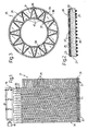
- Filter 35 comprises an outer casing formed by two coaxial tubular bodies 36, 37, defining an annular chamber 38 inbetween.
- the fabric 21, the surface provided with the conductive layer 24 of which is shown in phantom, is arranged into the annular chamber 38 substantially according to a closed polygonal line, the corners of which, angularly equidistant, are alternately joined to the tubular bodies 36 and 37.
- the fabric 21 forms with the tubular body 36 and with the tubular body 37, a plurality of spaces 39, 40, respectively communicating, in a not shown way, with an inlet aperture and with an outlet aperture of filter 35.
- FIG 4 a second example of an embodiment of a filter 50 using the fabric 21 of the kind described is partially illustrated.
- the fabric 21 is pleated and is fixed on a support layer 51 spiral wound into a not shown cylindric casing.
- the fabric 21 forms with the support layer 51 a plurality of spaces 52, 53 respectively communicating, in a not shown way, with an inlet aperture and with an outlet aperture of filter 50.
- FIG 5 a further embodiment of the conductive fabric is illustrated.
- the fabric 43 is subdivided in a plurality of portions 44, separated one another by insulating elements 45, formed for instance by strips of fabric from non conductive and oxidation resistant ceramic fibers. Portions 44 are realized from non conductive fibers, into which conductive fibers 46 schematically shown in phantom and arranged at random are incorporated.
- the fabric 43 has at an edge a plurality of electrodes 47, for instance metal foils, insulated each other by the elements 45 and apt to be connected through a control device of the kind described to a pole of the vehicle battery; fabric 43 further has, at an opposite edge, a further electrode 48 connecting portions 45 to the other pole of the battery.
- the operation of the filter is as follows.
- the exhaust gases emitted by the engine enter the filter 35 (figure 3) through an inlet aperture, not illustrated, and enter the spaces 39 included between the outher body 36 and the fabric 21.
- the gases pass then through the fabric 21, which intercepts the residual combustion products, and enter the spaces 40 included between said fabric 21 and the inner tubular body 37, from which they exit through a not shown outlet aperture.
- the exhaust gases enter through an inlet aperture, not illustrated, and enter the spaces 52; they pass then through the fabric 21, that intercepts the residual combustion products, and enter the spaces 53 from which they exit through a not shown outlet aperture.
- the build-up of residues in the fabric 21 originates a gradual clogging of the filter, creating a back-pressure in the engine exaust.
- the control exchange 16 as a result of a signal received, for instance, from a pressure sensor detecting the pressure difference of the exhaust gas between inlet and outlet from the filter 35 or 50, causes the closing of one of the switches 15, whereby one of the groups of threads 26 is electrically supplied.
- the flow of electric current through the threads 26 and the electrode 31 gives rise to a heating by Joule effect of the group of threads 26, till the combustion temperature of the residues is attained, which are oxidized and gassified freeing the porosity of the fabric 21.
- control exchange 16 disconnects the supply to the group of threads 26 and supplies the subsequent group of threads 26. All the groups are supplied in sequence, according to an order and for a time predetermined or governed from time to time by the control exchange 16. For instance, the exchange 16 can control the intensity of current and the heating time of each group of threads 26 as a function of the revolutions of the engine and of the rare of flow of the air passing through the filter by the action of an approprite device, for instance a fan or a positive-displacement pump.
- an approprite device for instance a fan or a positive-displacement pump.
- the conductive threads 26 of the fabric 21 can be supplied by groups according to a predetermined program, so as to assure in use the combustion of the residues accumulated in a well defined portion of the fabric 21; while this portion is regenerated, the residues build-up in other portions of the fabric 21, which will be regenerated in sequence. At the end of the regeneration of the last portion, the cycle starts again with the regeneration of the first regenerated portion, which in the meantime will have intercepted new residues.
- the "meshes" of the conductive layer 24 are suitably wide enough to allow the passage of the residues, that are intercepted, as schematically illustrated in figure 4, by the filtering layer 22.
- the concentration of the residues results substantially distributed around the conductors 26, which provide for the heating by direct conduction of those residues.
- the conduction between the opposite electrodes 47, 48 is assigned not to conductors having a definite geometry, such as the threads 26, but to conductive fibres 46 irregularly scattered in portions 44 mutually insulated of non-conductive fabric.
- the conductive portions (26; 44) of the filtering members (21; 43) are mutually insulated. This enables to obtain a selective and cyclic heating of the portions, with the advantage of reducing the electric power used and keeping under control the temperature of the filtering elements (21; 43), without any risk of clogging or of destruction due to over-heating. Further, the heating of the residues takes place through conduction, that is through direct contact between the residues themselves and the conductive portions (26; 44), which enables to exploit the most of the power supplied for the starting of the combustion, without great losses due to convection. Lastly, the filtering fabric elements (21; 43), thanks to their deformability, are particularly resistant to thermal shocks produced due to the sudden temperature variations during the heating and the cooling of the conductive portions (26; 44).
- the fibres used are suitably subjected to pre-tratments apt to avoid the embrittlement and/or the possible breakage due to phase transformation or anyway to other phenomena produced by thermal shocks.
- the pre-treatments can be of chemical and/or physical nature, and depending on the type of fiber used said treatments consist in the introduction or extraction of ions through diffusion in the material of the fiber.
- the filtering member can be produced with a combination of ceramic fabrics, felts or boards.
- the filtering member can comprise a series of stratified felt members; in particular, the single layers of the filtering member can be provided with pores having a geometric distribution, different dimensions and shapes, and arranged according to a porosity gradient.
- the electrification of the various elements can be carried out introducing in such elements electrically conductive fibres or threads. This solution enables to reduce the effect of the thermal shocks, in that the thermal conductivity is increased.
- a sliding element substantially arranged on a central plane of an inner chamber of the filter, in this case suitably formed with a quadrangular cross-section, and which can readily be introduced and extracted from the outer casing of the filter.
- control of the exchange 16 can control the switches 15 in response to signals received from the user and/or from process sensors (for instange temperature or pressure sensors) arranged inside or outside the filter; the electric current supplying the conductive portions (26; 44) can be modulated according to the temperature levels established in the filter.
- Means for the introduction of air into the filter can be provided, in order to assure a sufficient partial pressure of oxygen in the exhaust gases and so a complete combustion of the residues.
- At last catalysing additives can be provided suited to aid and optimise the combustion of the solid unburned particles.
- said additives can suitably comprise a mixture of one or more metal-oxides, for instance CuO, Cu2O, MnO2, Mn3O4, PbO, CeO2 or the respective oxygenated salts, for instance Cu(NO3)2, CuSO4, and of one or more chlorides of an alkaline or alkaline-earth metal for instance NaCl, KCl, LiCl, CuCl, CuCl2 , MgCl2, BaCl2, possibly also in the hydrated form; preferably said mixture comprises CuO and NaCl.
- Said mixture can be in a solid form (powder) or in the form of a solution in water or other solvent, and is deposited on the filtering member in the more convenient manner, such as insufflation, spraying or immersion.
Landscapes
- Engineering & Computer Science (AREA)
- Chemical & Material Sciences (AREA)
- Combustion & Propulsion (AREA)
- Mechanical Engineering (AREA)
- General Engineering & Computer Science (AREA)
- Processes For Solid Components From Exhaust (AREA)
- Filtering Materials (AREA)
- Filtering Of Dispersed Particles In Gases (AREA)
Claims (18)
- Regenerierbares Filter in den Auspuffgasen einer Brennkraftmaschine, mit einem äußeren Gehäuse, das wenigstens eine Einlaßleitung und eine Auslaßleitung aufweist, einer Filterschicht (21,43) aus Faser-Filtermaterial, welche Schicht in dem äußeren Gehäuse zwischen der Einlaßleitung und der Auslaßleitung liegt und die zurückgebliebenen Verbrennungsprodukte der Gase auffängt, einer elektrische Heizeinrichtung (26,46) in Verbindung mit der Filterschicht zum Anheben der Temperatur des Produkts, und einer selektiv und/oder zyklisch betätigbaren Steuereinrichtung (15,16) zur elektrischen Versorgung der Helzeinrichtung, dadurch gekennzeichnet, daß die Schicht die Form eines Filterstoffes (21,43) aufweist, daß die Heizeinrichtung elektrisch leitende Fasern (26,46) umfaßt, die in dem Filterstoff (21,43) eingeschlossen sind, daß der Filterstoff derart angeordnet ist, daß er eine Anzahl von langgestreckten Bereichen (26,46) aufweist, die elektrisch gegeneinander durch langgestreckte Isolierelemente (27,45) Isoliert sind und selektiv und/oder zyklisch elektrisch über die Steuereinrichtung (15,16) versorgt werden.
- Filter nach Anspruch 1, dadurch gekennzeichnet, daß die leitenden Fasern die Form von quergerichteten leitenden Fäden (26) aufweisen, die mit nichtleitenden längsgerichteten Fäden (25) verwebt sind und ein gewebtes Band (24) bilden, welche isolierenden Elemente die Form von quergerichteten, nichtleitenden Fäden (27) aufweisen, die ebenfalls mit den längsgerichteten Fäden (25) alternativ zu den leitenden Fäden (26) in dem gewebten Band (24) verwebt sind.
- Filter nach Anspruch 2, dadurch gekennzeichnet, daß der Stoff (21) eine Schicht (22) aus nichtleitenden keramischen Filterfasern enthält, die einen erheblichen Heizwiderstand aufweisen und mit einer Oberfläche (23) in Berührung mit dem gewebten Band (24) stehen, während die andere Oberfläche (29) der nichtleitenden Schicht (22) in Berührung mit einer Stützfadenschicht (28) steht.
- Filter nach Anspruch 2 oder 3, dadurch gekennzeichnet, daß die leitenden Fäden (26) in Gruppen angeordnet sind und daß die leitenden Fäden jeder Gruppe elektrisch parallel zueinander mit der Steuereinrichtung (15,16) verbunden sind und zugleich durch diese elektrisch versorgt werden.
- Filter nach Anspruch 4, dadurch gekennzeichnet, daß die leitenden Fäden (26) metallisch sind.
- Filter nach Anspruch 4, dadurch gekennzeichnet, daß die leitenden Fäden (26) aus leitendem keramischen Material bestehen.
- Filter nach Anspruch 6, dadurch gekennzeichnet, daß die leitenden Fäden (26) aus nichtleitendem keramischen Material bestehen, das mit einem leitenden Material beschichtet ist.
- Filter nach einem der Ansprüche 2 bis 7, dadurch gekennzeichnet, daß die quergerichteten Fäden (26,27) eine Anzahl von Mikrofäden umfassen.
- Filter nach Anspruch 3, dadurch gekennzeichnet, daß die leitenden Fasern (46) in einem nichtleitenden Material des Stoffes verteilt sind.
- Filter nach Anspruch 9, dadurch gekennzeichnet, daß das nichtleitende Material ein Keramikstoff ist.
- Filter nach Anspruch 9, dadurch gekennzeichnet, daß das nichtleitende Material ein keramischer Filz ist.
- Filter nach Anspruch 9, dadurch gekennzeichnet, daß das nichtleitende Material eine Anzahl von Filzschichten umfaßt, die übereinander liegen und progressiv sich ändernde Porositäten aufweisen.
- Filter nach Anspruch 9, dadurch gekennzeichnet, daß das nichtleitende Material ein auf Keramikbasis hergestelltes Papier ist.
- Filter nach einem der vorhergehenden Ansprüche, dadurch gekennzeichnet, daß der Stoff (21,43) innerhalb einer ringförmigen Kammer (38) des Filters (35) entsprechend einer geschlossenen, polygonalen Linie angeordnet ist, deren Ecken gleiche Winkelabstände aufweisen, und daß der Stoff alternativ mit einer inneren Wand (37) und einer äußeren Wand (36) der ringförmigen Kammer (38) verbunden ist.
- Filter nach einem der vorhergehenden Ansprüche, dadurch gekennzeichnet, daß der Stoff (21) gefaltet und an einem Trägerelement (51) befestigt ist.
- Filter nach Anspruch 15, dadurch gekennzeichnet, daß das Trägerelement (51) spiralförmig gewickelt ist.
- Filter nach Anspruch 15, dadurch gekennzeichnet, daß das Trägerelement als Schlitten ausgebildet ist, der im wesentlichen auf einer zentralen Ebene der inneren Kammer des Filters angeordnet ist.
- Filter nach einem der vorhergehenden Ansprüche, dadurch gekennzeichnet, daß der Filterstoff (21,43) mit einer Mischung besprüht ist, die wenigstens ein Metalloxid oder ein oxygeniertes Salz, das zur Bildung eines Metalloxids geeignet ist, und wenigstens ein Chlorid eines alkalischen oder erdalkalischen Metalls enthält.
Applications Claiming Priority (2)
| Application Number | Priority Date | Filing Date | Title |
|---|---|---|---|
| IT67909/86A IT1196822B (it) | 1986-12-05 | 1986-12-05 | Filtro autorigenerante per i gas di scarico di un motore a combustione interna |
| IT6790986 | 1986-12-05 |
Related Child Applications (1)
| Application Number | Title | Priority Date | Filing Date |
|---|---|---|---|
| EP90110810.0 Division-Into | 1987-12-02 |
Publications (2)
| Publication Number | Publication Date |
|---|---|
| EP0270990A1 EP0270990A1 (de) | 1988-06-15 |
| EP0270990B1 true EP0270990B1 (de) | 1991-08-07 |
Family
ID=11306291
Family Applications (2)
| Application Number | Title | Priority Date | Filing Date |
|---|---|---|---|
| EP87117828A Expired - Lifetime EP0270990B1 (de) | 1986-12-05 | 1987-12-02 | Regenerierbares Abgasfilter für Verbrennungsmotoren |
| EP90110810A Expired - Lifetime EP0393729B1 (de) | 1986-12-05 | 1987-12-02 | Regenerierbares Abgasfilter für Verbrennungsmotoren |
Family Applications After (1)
| Application Number | Title | Priority Date | Filing Date |
|---|---|---|---|
| EP90110810A Expired - Lifetime EP0393729B1 (de) | 1986-12-05 | 1987-12-02 | Regenerierbares Abgasfilter für Verbrennungsmotoren |
Country Status (5)
| Country | Link |
|---|---|
| EP (2) | EP0270990B1 (de) |
| JP (1) | JP2610147B2 (de) |
| DE (2) | DE3772013D1 (de) |
| ES (2) | ES2023398B3 (de) |
| IT (1) | IT1196822B (de) |
Cited By (1)
| Publication number | Priority date | Publication date | Assignee | Title |
|---|---|---|---|---|
| DE102021213700A1 (de) | 2021-12-02 | 2023-06-07 | Mahle International Gmbh | Filterelement insbesondere für eine Filtereinrichtung einer Frischluftanlage einer Brennkraftmaschine |
Families Citing this family (17)
| Publication number | Priority date | Publication date | Assignee | Title |
|---|---|---|---|---|
| AT405435B (de) * | 1988-11-30 | 1999-08-25 | Fleck Carl M Dr | Verfahren zur abscheidung und verbrennung von russpartikeln aus dieselabgasen und dieselabgasfilter zur durchführung des verfahrens |
| AU647491B2 (en) * | 1990-07-02 | 1994-03-24 | Carl M. Fleck | Process and device for cleaning exhaust gases |
| FR2667798B1 (fr) * | 1990-10-15 | 1993-06-11 | Aerospatiale | Filtre collecteur d'aerosols autochauffant pour pyrolyse. |
| JPH0661416B2 (ja) * | 1991-02-25 | 1994-08-17 | 日本碍子株式会社 | 排ガス処理装置 |
| JP3000750B2 (ja) * | 1991-09-20 | 2000-01-17 | 株式会社デンソー | 自己発熱型フィルタ |
| DK205191D0 (da) * | 1991-12-20 | 1991-12-20 | Per Stobbe | Roeggasfilter |
| IT1261725B (it) * | 1992-11-26 | 1996-05-30 | Iveco Fiat | Filtro rigenerabile per i gas di scarico di un motore a combustione interna. |
| JP2718615B2 (ja) * | 1993-03-12 | 1998-02-25 | 日本碍子株式会社 | 高温ガス用集塵装置 |
| DK29093D0 (da) * | 1993-03-15 | 1993-03-15 | Per Stobbe | Heated silicon carbide filter |
| ATA256293A (de) * | 1993-12-17 | 1998-10-15 | Fleck Carl M Dr | Elektrofilter zum abscheiden von russpartikeln aus den abgasen von brennkraftmaschinen |
| JP3885973B2 (ja) * | 1995-03-20 | 2007-02-28 | フランシス エー. エル. ジュリアン、 | 流体の流れに含まれる粒子の除去法とその装置 |
| JPH09217618A (ja) * | 1996-02-09 | 1997-08-19 | Isuzu Ceramics Kenkyusho:Kk | 排気ガス浄化装置 |
| FR2755623B1 (fr) * | 1996-11-12 | 1998-12-04 | Inst Francais Du Petrole | Procede et unite de filtration de gaz d'echappement, ayant un chauffage modulable |
| DE10023787A1 (de) * | 2000-05-15 | 2001-11-22 | Volkswagen Ag | Partikelfilter und Verfahren zur Regeneration eines Partikelfilters |
| CA2434282C (fr) * | 2001-01-19 | 2009-11-17 | Institut Francais Du Petrole | Separateur en matiere poreuse fibreuse, telle qu'un feutre |
| DE102018104140A1 (de) | 2018-02-23 | 2019-08-29 | Volkswagen Aktiengesellschaft | Partikelfilter für einen Verbrennungsmotor sowie Verfahren zur Herstellung eines solchen Partikelfilters |
| EP3695895B1 (de) * | 2019-02-14 | 2021-12-22 | Carl Freudenberg KG | Filterelement mit wabenkörper zur luftreinigung |
Citations (1)
| Publication number | Priority date | Publication date | Assignee | Title |
|---|---|---|---|---|
| EP0244061A1 (de) * | 1986-02-28 | 1987-11-04 | Porous Element Technology Limited | Einrichtung zur Beseitigung von partikelförmigem Material aus einem Gas |
Family Cites Families (14)
| Publication number | Priority date | Publication date | Assignee | Title |
|---|---|---|---|---|
| US3937015A (en) * | 1973-05-03 | 1976-02-10 | Nippondenso Co., Ltd. | Pleated filter in the exhaust manifold |
| DE2951316A1 (de) * | 1979-12-20 | 1981-07-02 | Degussa Ag, 6000 Frankfurt | Katalytisches filter fuer die dieselabgasreinigung |
| US4276066A (en) * | 1980-02-25 | 1981-06-30 | General Motors Corporation | Monolith diesel exhaust filter with self-regeneration |
| JPS6053165B2 (ja) * | 1981-03-16 | 1985-11-25 | 株式会社豊田中央研究所 | 内燃機関排気吐煙の捕集装置 |
| US4505107A (en) * | 1981-10-26 | 1985-03-19 | Nippondenso Co., Ltd. | Exhaust gas cleaning apparatus |
| JPS58119317A (ja) * | 1981-12-29 | 1983-07-15 | Ngk Spark Plug Co Ltd | 可燃性微粒子除去用フイルタ装置 |
| JPS58137423A (ja) * | 1982-02-09 | 1983-08-15 | Ngk Spark Plug Co Ltd | 排ガス用フイルタ装置 |
| JPS58143817A (ja) * | 1982-02-19 | 1983-08-26 | Ngk Spark Plug Co Ltd | 可燃性微粒子除去用フイルタ装置 |
| JPS58174216A (ja) * | 1982-04-03 | 1983-10-13 | Ngk Spark Plug Co Ltd | 可燃性微粒子除去用フイルタ |
| JPS58199018A (ja) * | 1982-05-18 | 1983-11-19 | Nippon Denso Co Ltd | 電気的加熱手段を有する排気ガス微粒子浄化装置 |
| JPS58210310A (ja) * | 1982-06-01 | 1983-12-07 | Nippon Denso Co Ltd | 内燃機関のカ−ボン微粒子浄化装置 |
| US4455823A (en) * | 1982-10-20 | 1984-06-26 | General Motors Corporation | Diesel exhaust particulate trap with pleated filter |
| US4462812A (en) * | 1982-12-08 | 1984-07-31 | General Motors Corporation | Ceramic monolith particulate trap including filter support |
| US4503672A (en) * | 1983-11-25 | 1985-03-12 | General Motors Corporation | Diesel exhaust cleaner with glow plug igniters and flow limiting valve |
-
1986
- 1986-12-05 IT IT67909/86A patent/IT1196822B/it active
-
1987
- 1987-12-02 DE DE8787117828T patent/DE3772013D1/de not_active Expired - Lifetime
- 1987-12-02 ES ES87117828T patent/ES2023398B3/es not_active Expired - Lifetime
- 1987-12-02 EP EP87117828A patent/EP0270990B1/de not_active Expired - Lifetime
- 1987-12-02 ES ES199090110810T patent/ES2035681T3/es not_active Expired - Lifetime
- 1987-12-02 DE DE9090110810T patent/DE3782176T2/de not_active Expired - Fee Related
- 1987-12-02 EP EP90110810A patent/EP0393729B1/de not_active Expired - Lifetime
- 1987-12-05 JP JP30686887A patent/JP2610147B2/ja not_active Expired - Fee Related
Patent Citations (1)
| Publication number | Priority date | Publication date | Assignee | Title |
|---|---|---|---|---|
| EP0244061A1 (de) * | 1986-02-28 | 1987-11-04 | Porous Element Technology Limited | Einrichtung zur Beseitigung von partikelförmigem Material aus einem Gas |
Cited By (1)
| Publication number | Priority date | Publication date | Assignee | Title |
|---|---|---|---|---|
| DE102021213700A1 (de) | 2021-12-02 | 2023-06-07 | Mahle International Gmbh | Filterelement insbesondere für eine Filtereinrichtung einer Frischluftanlage einer Brennkraftmaschine |
Also Published As
| Publication number | Publication date |
|---|---|
| JPS63197511A (ja) | 1988-08-16 |
| EP0393729A2 (de) | 1990-10-24 |
| IT8667909A0 (it) | 1986-12-05 |
| DE3772013D1 (de) | 1991-09-12 |
| EP0393729B1 (de) | 1992-10-07 |
| EP0270990A1 (de) | 1988-06-15 |
| ES2035681T3 (es) | 1993-04-16 |
| EP0393729A3 (en) | 1990-11-28 |
| JP2610147B2 (ja) | 1997-05-14 |
| DE3782176D1 (de) | 1992-11-12 |
| IT1196822B (it) | 1988-11-25 |
| DE3782176T2 (de) | 1993-05-06 |
| ES2023398B3 (es) | 1992-01-16 |
Similar Documents
| Publication | Publication Date | Title |
|---|---|---|
| US5207807A (en) | Regenerable filter for exhaust gases of an internal-combustion engine | |
| EP0393729B1 (de) | Regenerierbares Abgasfilter für Verbrennungsmotoren | |
| US4427418A (en) | Device for collecting particulates in exhaust gases | |
| US5258164A (en) | Electrically regenerable diesel particulate trap | |
| EP0608783B1 (de) | Elektrisch regenierbare Dieselpartikelfilterpatrone und Filter | |
| US5405422A (en) | Self-heating filter | |
| US3533753A (en) | Catalyst for engine exhaust-gas reformation | |
| US4283207A (en) | Diesel exhaust filter-incinerator | |
| US5571298A (en) | Regeneratable filter for combustible particles, particularly soot filter | |
| KR100890419B1 (ko) | 입자상 물질 제거 장치 | |
| US4641496A (en) | Continuous rotary regeneration system for a particulate trap | |
| US4791785A (en) | Removal of particulate material from a gas | |
| EP0657631B1 (de) | Dieselpartikelfilter | |
| JPH0211287B2 (de) | ||
| EP1187973A1 (de) | Elektrisch regenerierbarer dieselabgasfilter | |
| JP3677329B2 (ja) | 排ガス中の炭素系微粒子処理用フィルタ及びこれを用いた炭素系微粒子処理装置 | |
| JPH11166409A (ja) | 排気ガス用のフィルタ装置 | |
| EP0599323B1 (de) | Regenerierbarer Filter für die Abgase eines Verbrennungsmotors | |
| JPH116419A (ja) | フィルタの再生方法およびフィルタ装置 | |
| JP2002047915A (ja) | 排気微粒子除去装置 | |
| JPH10272325A (ja) | 微粒子処理装置 | |
| JPH06264722A (ja) | フィルタ装置 | |
| KR100628826B1 (ko) | 배기 가스 처리 장치 | |
| JP3078940B2 (ja) | 排気ガス処理装置 | |
| JP3078941B2 (ja) | 排気ガス処理装置 |
Legal Events
| Date | Code | Title | Description |
|---|---|---|---|
| PUAI | Public reference made under article 153(3) epc to a published international application that has entered the european phase |
Free format text: ORIGINAL CODE: 0009012 |
|
| AK | Designated contracting states |
Kind code of ref document: A1 Designated state(s): BE DE ES FR GB IT NL SE |
|
| 17P | Request for examination filed |
Effective date: 19881124 |
|
| 17Q | First examination report despatched |
Effective date: 19890321 |
|
| GRAA | (expected) grant |
Free format text: ORIGINAL CODE: 0009210 |
|
| AK | Designated contracting states |
Kind code of ref document: B1 Designated state(s): BE DE ES FR GB IT NL SE |
|
| XX | Miscellaneous (additional remarks) |
Free format text: TEILANMELDUNG 90110810.0 EINGEREICHT AM 02/12/87. |
|
| REF | Corresponds to: |
Ref document number: 3772013 Country of ref document: DE Date of ref document: 19910912 |
|
| ET | Fr: translation filed | ||
| ITF | It: translation for a ep patent filed | ||
| REG | Reference to a national code |
Ref country code: ES Ref legal event code: FG2A Ref document number: 2023398 Country of ref document: ES Kind code of ref document: B3 |
|
| PLBE | No opposition filed within time limit |
Free format text: ORIGINAL CODE: 0009261 |
|
| STAA | Information on the status of an ep patent application or granted ep patent |
Free format text: STATUS: NO OPPOSITION FILED WITHIN TIME LIMIT |
|
| 26N | No opposition filed | ||
| EAL | Se: european patent in force in sweden |
Ref document number: 87117828.1 |
|
| REG | Reference to a national code |
Ref country code: GB Ref legal event code: IF02 |
|
| PGFP | Annual fee paid to national office [announced via postgrant information from national office to epo] |
Ref country code: FR Payment date: 20021120 Year of fee payment: 16 |
|
| PGFP | Annual fee paid to national office [announced via postgrant information from national office to epo] |
Ref country code: ES Payment date: 20021128 Year of fee payment: 16 |
|
| PGFP | Annual fee paid to national office [announced via postgrant information from national office to epo] |
Ref country code: DE Payment date: 20021231 Year of fee payment: 16 |
|
| PGFP | Annual fee paid to national office [announced via postgrant information from national office to epo] |
Ref country code: GB Payment date: 20031125 Year of fee payment: 17 |
|
| PGFP | Annual fee paid to national office [announced via postgrant information from national office to epo] |
Ref country code: BE Payment date: 20031128 Year of fee payment: 17 |
|
| PGFP | Annual fee paid to national office [announced via postgrant information from national office to epo] |
Ref country code: NL Payment date: 20031202 Year of fee payment: 17 |
|
| PG25 | Lapsed in a contracting state [announced via postgrant information from national office to epo] |
Ref country code: ES Free format text: LAPSE BECAUSE OF NON-PAYMENT OF DUE FEES Effective date: 20031203 |
|
| PGFP | Annual fee paid to national office [announced via postgrant information from national office to epo] |
Ref country code: SE Payment date: 20031205 Year of fee payment: 17 |
|
| PG25 | Lapsed in a contracting state [announced via postgrant information from national office to epo] |
Ref country code: DE Free format text: LAPSE BECAUSE OF NON-PAYMENT OF DUE FEES Effective date: 20040701 |
|
| PG25 | Lapsed in a contracting state [announced via postgrant information from national office to epo] |
Ref country code: FR Free format text: LAPSE BECAUSE OF NON-PAYMENT OF DUE FEES Effective date: 20040831 |
|
| REG | Reference to a national code |
Ref country code: FR Ref legal event code: ST |
|
| PG25 | Lapsed in a contracting state [announced via postgrant information from national office to epo] |
Ref country code: GB Free format text: LAPSE BECAUSE OF NON-PAYMENT OF DUE FEES Effective date: 20041202 |
|
| PG25 | Lapsed in a contracting state [announced via postgrant information from national office to epo] |
Ref country code: SE Free format text: LAPSE BECAUSE OF NON-PAYMENT OF DUE FEES Effective date: 20041203 |
|
| PG25 | Lapsed in a contracting state [announced via postgrant information from national office to epo] |
Ref country code: BE Free format text: LAPSE BECAUSE OF NON-PAYMENT OF DUE FEES Effective date: 20041231 |
|
| REG | Reference to a national code |
Ref country code: ES Ref legal event code: FD2A Effective date: 20031203 |
|
| BERE | Be: lapsed |
Owner name: *IVECO FIAT S.P.A. Effective date: 20041231 |
|
| PG25 | Lapsed in a contracting state [announced via postgrant information from national office to epo] |
Ref country code: NL Free format text: LAPSE BECAUSE OF NON-PAYMENT OF DUE FEES Effective date: 20050701 |
|
| GBPC | Gb: european patent ceased through non-payment of renewal fee |
Effective date: 20041202 |
|
| EUG | Se: european patent has lapsed | ||
| NLV4 | Nl: lapsed or anulled due to non-payment of the annual fee |
Effective date: 20050701 |
|
| PG25 | Lapsed in a contracting state [announced via postgrant information from national office to epo] |
Ref country code: IT Free format text: LAPSE BECAUSE OF NON-PAYMENT OF DUE FEES;WARNING: LAPSES OF ITALIAN PATENTS WITH EFFECTIVE DATE BEFORE 2007 MAY HAVE OCCURRED AT ANY TIME BEFORE 2007. THE CORRECT EFFECTIVE DATE MAY BE DIFFERENT FROM THE ONE RECORDED. Effective date: 20051202 |
|
| BERE | Be: lapsed |
Owner name: *IVECO FIAT S.P.A. Effective date: 20041231 |