EP0269624B1 - Fibre-optic lasers and amplifiers - Google Patents
Fibre-optic lasers and amplifiers Download PDFInfo
- Publication number
- EP0269624B1 EP0269624B1 EP86904884A EP86904884A EP0269624B1 EP 0269624 B1 EP0269624 B1 EP 0269624B1 EP 86904884 A EP86904884 A EP 86904884A EP 86904884 A EP86904884 A EP 86904884A EP 0269624 B1 EP0269624 B1 EP 0269624B1
- Authority
- EP
- European Patent Office
- Prior art keywords
- fibre
- laser
- dopant ions
- cavity
- optical
- Prior art date
- Legal status (The legal status is an assumption and is not a legal conclusion. Google has not performed a legal analysis and makes no representation as to the accuracy of the status listed.)
- Revoked
Links
Images



Classifications
-
- H—ELECTRICITY
- H01—ELECTRIC ELEMENTS
- H01S—DEVICES USING THE PROCESS OF LIGHT AMPLIFICATION BY STIMULATED EMISSION OF RADIATION [LASER] TO AMPLIFY OR GENERATE LIGHT; DEVICES USING STIMULATED EMISSION OF ELECTROMAGNETIC RADIATION IN WAVE RANGES OTHER THAN OPTICAL
- H01S3/00—Lasers, i.e. devices using stimulated emission of electromagnetic radiation in the infrared, visible or ultraviolet wave range
- H01S3/14—Lasers, i.e. devices using stimulated emission of electromagnetic radiation in the infrared, visible or ultraviolet wave range characterised by the material used as the active medium
- H01S3/16—Solid materials
- H01S3/17—Solid materials amorphous, e.g. glass
-
- C—CHEMISTRY; METALLURGY
- C03—GLASS; MINERAL OR SLAG WOOL
- C03B—MANUFACTURE, SHAPING, OR SUPPLEMENTARY PROCESSES
- C03B37/00—Manufacture or treatment of flakes, fibres, or filaments from softened glass, minerals, or slags
- C03B37/01—Manufacture of glass fibres or filaments
- C03B37/012—Manufacture of preforms for drawing fibres or filaments
- C03B37/014—Manufacture of preforms for drawing fibres or filaments made entirely or partially by chemical means, e.g. vapour phase deposition of bulk porous glass either by outside vapour deposition [OVD], or by outside vapour phase oxidation [OVPO] or by vapour axial deposition [VAD]
- C03B37/018—Manufacture of preforms for drawing fibres or filaments made entirely or partially by chemical means, e.g. vapour phase deposition of bulk porous glass either by outside vapour deposition [OVD], or by outside vapour phase oxidation [OVPO] or by vapour axial deposition [VAD] by glass deposition on a glass substrate, e.g. by inside-, modified-, plasma- or plasma modified- chemical vapour deposition [ICVD, MCVD, PCVD, PMCVD], i.e. by thin layer coating on the inside or outside of a glass tube or on a glass rod
-
- C—CHEMISTRY; METALLURGY
- C03—GLASS; MINERAL OR SLAG WOOL
- C03B—MANUFACTURE, SHAPING, OR SUPPLEMENTARY PROCESSES
- C03B37/00—Manufacture or treatment of flakes, fibres, or filaments from softened glass, minerals, or slags
- C03B37/01—Manufacture of glass fibres or filaments
- C03B37/012—Manufacture of preforms for drawing fibres or filaments
- C03B37/014—Manufacture of preforms for drawing fibres or filaments made entirely or partially by chemical means, e.g. vapour phase deposition of bulk porous glass either by outside vapour deposition [OVD], or by outside vapour phase oxidation [OVPO] or by vapour axial deposition [VAD]
- C03B37/018—Manufacture of preforms for drawing fibres or filaments made entirely or partially by chemical means, e.g. vapour phase deposition of bulk porous glass either by outside vapour deposition [OVD], or by outside vapour phase oxidation [OVPO] or by vapour axial deposition [VAD] by glass deposition on a glass substrate, e.g. by inside-, modified-, plasma- or plasma modified- chemical vapour deposition [ICVD, MCVD, PCVD, PMCVD], i.e. by thin layer coating on the inside or outside of a glass tube or on a glass rod
- C03B37/01807—Reactant delivery systems, e.g. reactant deposition burners
-
- G—PHYSICS
- G02—OPTICS
- G02B—OPTICAL ELEMENTS, SYSTEMS OR APPARATUS
- G02B6/00—Light guides; Structural details of arrangements comprising light guides and other optical elements, e.g. couplings
- G02B6/02—Optical fibres with cladding with or without a coating
-
- H—ELECTRICITY
- H01—ELECTRIC ELEMENTS
- H01S—DEVICES USING THE PROCESS OF LIGHT AMPLIFICATION BY STIMULATED EMISSION OF RADIATION [LASER] TO AMPLIFY OR GENERATE LIGHT; DEVICES USING STIMULATED EMISSION OF ELECTROMAGNETIC RADIATION IN WAVE RANGES OTHER THAN OPTICAL
- H01S3/00—Lasers, i.e. devices using stimulated emission of electromagnetic radiation in the infrared, visible or ultraviolet wave range
- H01S3/05—Construction or shape of optical resonators; Accommodation of active medium therein; Shape of active medium
- H01S3/06—Construction or shape of active medium
- H01S3/063—Waveguide lasers, i.e. whereby the dimensions of the waveguide are of the order of the light wavelength
- H01S3/067—Fibre lasers
-
- H—ELECTRICITY
- H01—ELECTRIC ELEMENTS
- H01S—DEVICES USING THE PROCESS OF LIGHT AMPLIFICATION BY STIMULATED EMISSION OF RADIATION [LASER] TO AMPLIFY OR GENERATE LIGHT; DEVICES USING STIMULATED EMISSION OF ELECTROMAGNETIC RADIATION IN WAVE RANGES OTHER THAN OPTICAL
- H01S3/00—Lasers, i.e. devices using stimulated emission of electromagnetic radiation in the infrared, visible or ultraviolet wave range
- H01S3/05—Construction or shape of optical resonators; Accommodation of active medium therein; Shape of active medium
- H01S3/08—Construction or shape of optical resonators or components thereof
- H01S3/081—Construction or shape of optical resonators or components thereof comprising three or more reflectors
- H01S3/083—Ring lasers
-
- C—CHEMISTRY; METALLURGY
- C03—GLASS; MINERAL OR SLAG WOOL
- C03B—MANUFACTURE, SHAPING, OR SUPPLEMENTARY PROCESSES
- C03B2201/00—Type of glass produced
- C03B2201/06—Doped silica-based glasses
- C03B2201/30—Doped silica-based glasses doped with metals, e.g. Ga, Sn, Sb, Pb or Bi
- C03B2201/34—Doped silica-based glasses doped with metals, e.g. Ga, Sn, Sb, Pb or Bi doped with rare earth metals, i.e. with Sc, Y or lanthanides, e.g. for laser-amplifiers
-
- C—CHEMISTRY; METALLURGY
- C03—GLASS; MINERAL OR SLAG WOOL
- C03B—MANUFACTURE, SHAPING, OR SUPPLEMENTARY PROCESSES
- C03B2201/00—Type of glass produced
- C03B2201/06—Doped silica-based glasses
- C03B2201/30—Doped silica-based glasses doped with metals, e.g. Ga, Sn, Sb, Pb or Bi
- C03B2201/40—Doped silica-based glasses doped with metals, e.g. Ga, Sn, Sb, Pb or Bi doped with transition metals other than rare earth metals, e.g. Zr, Nb, Ta or Zn
-
- G—PHYSICS
- G02—OPTICS
- G02B—OPTICAL ELEMENTS, SYSTEMS OR APPARATUS
- G02B6/00—Light guides; Structural details of arrangements comprising light guides and other optical elements, e.g. couplings
- G02B6/24—Coupling light guides
- G02B6/26—Optical coupling means
- G02B6/28—Optical coupling means having data bus means, i.e. plural waveguides interconnected and providing an inherently bidirectional system by mixing and splitting signals
- G02B6/293—Optical coupling means having data bus means, i.e. plural waveguides interconnected and providing an inherently bidirectional system by mixing and splitting signals with wavelength selective means
- G02B6/29346—Optical coupling means having data bus means, i.e. plural waveguides interconnected and providing an inherently bidirectional system by mixing and splitting signals with wavelength selective means operating by wave or beam interference
- G02B6/29358—Multiple beam interferometer external to a light guide, e.g. Fabry-Pérot, etalon, VIPA plate, OTDL plate, continuous interferometer, parallel plate resonator
- G02B6/29359—Cavity formed by light guide ends, e.g. fibre Fabry Pérot [FFP]
-
- G—PHYSICS
- G02—OPTICS
- G02B—OPTICAL ELEMENTS, SYSTEMS OR APPARATUS
- G02B6/00—Light guides; Structural details of arrangements comprising light guides and other optical elements, e.g. couplings
- G02B6/24—Coupling light guides
- G02B6/26—Optical coupling means
- G02B6/28—Optical coupling means having data bus means, i.e. plural waveguides interconnected and providing an inherently bidirectional system by mixing and splitting signals
- G02B6/293—Optical coupling means having data bus means, i.e. plural waveguides interconnected and providing an inherently bidirectional system by mixing and splitting signals with wavelength selective means
- G02B6/29379—Optical coupling means having data bus means, i.e. plural waveguides interconnected and providing an inherently bidirectional system by mixing and splitting signals with wavelength selective means characterised by the function or use of the complete device
- G02B6/29395—Optical coupling means having data bus means, i.e. plural waveguides interconnected and providing an inherently bidirectional system by mixing and splitting signals with wavelength selective means characterised by the function or use of the complete device configurable, e.g. tunable or reconfigurable
Definitions
- This invention concerns improvements in or relating to fibre-optic lasers and amplifiers, these being active devices of the type in which useful gain is afforded by the stimulated emission of radiation.
- These devices comprise: a length of fibre, in which is incorporated a distribution of active dopant ions; and, an optical-pumping source coupled to the fibre.
- Hybrid semiconductor-diode and optical fibre technologies are both well advanced. However, full integration of the components of these technologies has yet to be achieved. There is a need for active devices that would be readily compatible with single-mode fibre systems and that accordingly could bridge these technologies.
- the laser described comprised stub lengths of fibre (about 1 cm length) with core diameters ranging from 800 to 15 microns. Continuous (cw) lasing action was demonstrated using an end-coupled gallium arsenide (GaAs) injection laser as optical pumping source.
- GaAs gallium arsenide
- US-A-3,729,690 specifically describes the fabrication of a side pumped laser from barium crown glass doped with neodymium. It also teaches that in general a fibre laser may be fabricated from a glass selected from the group including commercially available inorganic glasses such as soda-lime glass, barium crown glass, flint glass, lead glass, arsenic trisulphide glass and the like and also certain commercially available plastics, glycerine and other devitrified sugar substances, and mixtures of organic solutions which, when cooled, form clear glasses such as E.P.A. (ether, isopentane and alcohol).
- E.P.A. ether, isopentane and alcohol
- the glass is doped with an active laser ingredient selected from the group including Praseodymium +++ , Neodymium +++ , Samarium ++ , Samarium +++ , Europium ++ , Europium +++ , Uranium +++ , Terbium +++ , Holmium +++ , Erbium +++ , Thulium +++ , Dyprosium +++ , Yitterbium +++ , and Cerium +++ .
- an active laser ingredient selected from the group including Praseodymium +++ , Neodymium +++ , Samarium ++ , Samarium +++ , Europium ++ , Europium +++ , Uranium +++ , Terbium +++ , Holmium +++ , Erbium +++ , Thulium +++ , Dyprosium +++ , Yitterbium +++ , and Cerium +++ .
- Other than neodymium these selections are not exemp
- the present invention is intended to meet the need aforesaid, and to provide a fibre-laser or amplifier capable of single-mode operation and compatible with single-mode fibre systems.
- a fibre-optic laser or amplifier being an active device of the type in which gain is provided by the stimulated emission of radiation, this device comprising:
- fibre of single-mode geometry a fibre having a step-index profile.
- Other types of single mode fibre are not precluded from the scope of this invention and may have the form of polarisation maintaining fibres, polarising fibres dispersion-shifted fibres and helical-core fibres.
- Dopants may be incorporated in the fibre core, in the fibre cladding or in both. More than one dopant species may be incorporated to extend device versatility.
- fibres are fully compatible with existing fibre devices such as fused couplers, polarisers, filters and phase modulators, (eg to achieve single polarisation operation, wavelength selection, mode locking and Q-switching), and consequently it is possible to envisage a new all-fibre laser/amplifier technology.
- existing fibre devices such as fused couplers, polarisers, filters and phase modulators, (eg to achieve single polarisation operation, wavelength selection, mode locking and Q-switching), and consequently it is possible to envisage a new all-fibre laser/amplifier technology.
- Single-mode fibre lasers and amplifiers possess a number of advantages over their bulk counterparts. By virtue of their small cores (typically 8 ⁇ m diameter and less), very-low thresholds ( ⁇ 100 ⁇ W) and high gains can be achieved. Also since typically fibre diameters overall are about 100 ⁇ m, thermal effects prove to be minimal.
- dopant concentration is so low, manufacture can be economical.
- a typical device might use as little as 0.1 ⁇ g of dopant oxide.
- fibres of a relatively long length eg 5 cm and greater up to at least 300 m, (the length of the fibre serves as a cladding mode filter and gain is distributed), compact devices can be produced.
- a coiled 1 m length fibre laser can be readily fitted into a 1 cm 3 enclosure.
- Silica if selected as the fibre host medium, has good power handling characteristics. Moreover in the presence of a high silica glass host, the optical transitions of the rare-earth or transition metal dopant ions are substantially broadened. This, as detailed below allows the realisation of both tunable lasers and broad-band amplifiers.
- the active devices considered herein provide improved sources/amplifiers for telecommunications applications because they can handle high powers without damage, they provide smaller/lighter/cheaper general purpose active devices and may in conjunction with other fibre devices (eg gratings) provide new and powerful signal processing functions. Note also that non-linear effects can be readily achieved at the optical power levels obtained in fibre lasers, affording exploitation of a number of simultaneous laser and non-linear effects.
- a single-mode geometry step-index profile fibre with a germania/silica core doped with 300 ppm of Nd 3+ , cut off wavelength of 1 ⁇ m and an index difference of 1% was fabricated using the method described in our earlier filed patent application No 8520300 dated 13 Aug 1985, published details of which appear in the article "Fabrication of low-loss optical fibres containing rare-earth ions" mentioned hereinbefore.
- high-purity hydrated neodymium trichloride is used as dopant source during a modified chemical vapour deposition (MCVD) process.
- MCVD modified chemical vapour deposition
- Cladding glass material such as SiO 2 - B 2 O 3 is deposited on the inside wall of a heated silica tube in conventional manner. Thereafter the carrier chamber is preheated to above 1000 °C to obtain a desired vapour pressure. During core deposition the reactants (typically GeCl 4 and SiCl 4 ) are mixed with oxygen and passed through the heated dopant chamber where controlled amounts of the rare-earth halide are entrained in the gas flow. The temperature of the MCVD hot zone is chosen such that it is not hot enough to fuse the deposited core-glass layers. This essential feature enables further drying of the materials prior to fusion. This latter drying step is performed by prolonged heating at 900°C or so in the presence of eg. a chlorine gas flow. The unsintered layer is then fused to form a glassy layer, the preform collapsed and a fibre drawn to the described geometry.
- the reactants typically GeCl 4 and SiCl 4
- the temperature of the MCVD hot zone is chosen such that it is not hot enough
- Figure 1 shows the experimental configuration.
- the fibre ends 3, 5 were cleaved and directly butted to dielectric mirrors 7, 9 having a high reflectivity ( ⁇ 99.5%) at the lasing wavelength and high transmittance ( ⁇ 80%) for the pump.
- a York Technology cleaving tool type No. 007 was used and the fibre ends 3, 5 inspected before index-matching to the mirrors 7, 9.
- reflective coatings eg. multi-layer dielectric coatings can be deposited directly onto the fibre end faces.
- End pumping was by a single-mode GaA1As Laser 11 (Hitachi HLP 1400), which was focussed by a lens arrangement 13, 15 and launched into the fibre with an efficiency of 16%. Lasing threshold was observed for a total semiconductor laser power of 600 ⁇ W. This corresponds to an estimated absorped pump-power of only 100 ⁇ W in the 2 m long fibre 1 and is an indication of the very low intracavity losses.
- the output power as a function of pump power for the fibre Laser is shown in figure 2. No saturation of the output was observed at pump powers up to the maximum available ( 20 mW). Operation of the laser at reduced duty cycle gave no decrease in lasing threshold, indicating that thermal effects are negligible.
- the fibre laser can therefore be easily operated CW without auxiliary cooling, unlike previous neodymium-doped glass lasers. Modulation of the pump produced relaxation oscillations, from which a cavity finesse of 300 was calculated.
- the wavelength of operation of the fibre laser was measured to be 1.088 ⁇ m i.e. shifted by approximately 30 nm to longer wavelengths than would be expected for conventional neodymium glass lasers.
- a fibre grating may be used in place of the end mirror 9 and may be spliced to or formed in the doped fibre (1).
- the described laser cavity may be modified to afford Q-Switching.
- a typical arrangement is shown in Figure 3.
- a microscope objective 17, an acousto-optic deflector 19 and an output mirror 21 are employed in place of the abutted mirror 9 of figure 1.
- the fibre 1 used had the following characteristics: 3.5 ⁇ m core diameter, NA of 0.21, length 3.2 m and a total absorption at the pump wavelength of 97% (corresponding to 300 ppm nd 3+ content).
- the loss at the lasing wavelength (1.088 m) was negligable ( 10dB/km).
- the fibre ends 3, 5 were cleaved and one end 3 butted to the input dielectric mirror 7.
- the pump source 11 used was as above and light was launched into the fibre with an efficiency of approximately 25%.
- the CW threshold was 3.7 mW absorbed.
- the acousto-optic deflector 19 was used in transmission mode, the high-Q state being achieved by electronically removing the applied RF with 2 ⁇ s duration pulses.
- the output mirror 21 used in this configuration had a transmission at the lasing wavelength of 12%. Pulse repetition rate was variable between single shot and 4 kH z with no change in peak output power or pulse duration.
- a mechanical chopper with a mark-space ratio of 1:300 was substituted in the cavity to provide an alternative method of Q-switching.
- output pulses of peak power greater than 300 mW and FWHM of 500 nS at a repetition rate of 400 Hz were then obtained.
- a saturable absorber may also be used for Q-switching and mode-locking. Possibly this could be incorporated within the fibre as an additional dopant.
- the Q-switch arrangement of figure 3 may be supplemented with a beam splitter 23 and a reflection grating 25 as shown in Figure 4.
- a 5 m length of Nd 3+ doped fibre 1 with 15 dB/m unsaturated absorption at 514 nm was used as gain medium.
- An argon-ion laser was used as pump source.
- An intracavity pellicle was used as the beam splitter/output coupler 23. The lasing wavelength could be selected by changing the angle of the grating 25.
- the laser was widely tunable, being tunable over an 80 nm region from 1065 nm to 1145 nm. Threshold occurred at 25 mW input corresponding to only 10 mW absorbed in the fibre. Pulsed and cw operation were demonstrated.
- rare earth or transition metal dopants can be incorporated in fibre using the technique described, using the appropriate halide dopant precursor. These also exhibit high absorption bands at practical pump wavelengths and low-loss windows at useful emission wavelengths. This is illustrated for the rare-earths erbium (Er 3+ ) and terbium (Tb 3+ ) in Figure 5.
- the long lengths of fibre 1 may be coiled to afford compact packaging. It is also possible to construct ring-cavity laser structures, an example of which is shown in Figure 8.
- a fibre ring 27 (diameter 70 cm) was produced by splicing together two ports of a fused tapered-coupler 29 made from Nd 3+ doped fibre.
- the coupler 29 was designed so that more than 80% of the power of a dye-laser pump 31 at 595 nm was coupled into the ring 27, while at the lasing wavelength less than 10% per round trip was extracted. Coupler losses were measured to be 3 dB at 633 nm (fibre multi-mode), and 1 dB at 1 ⁇ m.
- the fibre used was as in the previous embodiment ( Figure 1), although the absorption at the dye-laser pump wavelength of 595 nm is considerably higher (30 dB/m).
- the pump radiation should be largely absorbed within the ring 27 and not in the leads 26. It is therefore an advantage to construct the coupler 29 from one undoped and one doped fibre, such that the leads do not absorb at the pump wavelength.
- Lasing threshold was observed at a dye-laser pump power of 80 mW, which, owing to coupler losses and lead absorption, corresponds to a few milliwatts absorbed in the ring.
- the ring-laser ouput was 2 mW. Allowing for bi-directional ring-laser ouput, the slope efficiency is estimated to be approximately 20%.
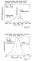
- the lasing wavelength was centred at 1.078 ⁇ m with a full-width half maximum spectral-width of 4 nm (see figure 9). The shift of 10 nm from the linear configuration is due to a slight mismatch between the coupler wavelength response and the laser gain curve. It may thus be possible to tune the laser wavelength over the full gain curve (90 nm width) by varying the coupler characteristics.
- FIG 10. An amplifier arrangement is shown in figure 10. This is constructed using an open-ended 4-port coupler 29, 33 comprised of doped fibre 1. As shown this is inserted into a length of conventional transmission fibre 35. Signal at emission wavelength is propagated along the main fibre 1 which serves as gain medium. Pumping radiation from the source 31 is coupled to the coupling fibre 33 and thence into the main fibre 1.
- a single pass gain of 25 dB has been measured for a 3 m length of erbium-doped fibre (300 ppm Er 2+ ) using a similar arrangement.
- the optical feedback resulting from Fresnel reflections was reduced by index matching one end of the fibre.
- splicing the fibre into a fibre system would be sufficient to largely eliminate etalon effects, since low-reflectivity splices are readily achievable.
Landscapes
- Physics & Mathematics (AREA)
- Engineering & Computer Science (AREA)
- Electromagnetism (AREA)
- Chemical & Material Sciences (AREA)
- Optics & Photonics (AREA)
- Plasma & Fusion (AREA)
- General Life Sciences & Earth Sciences (AREA)
- Chemical Kinetics & Catalysis (AREA)
- Materials Engineering (AREA)
- Organic Chemistry (AREA)
- Geochemistry & Mineralogy (AREA)
- Life Sciences & Earth Sciences (AREA)
- General Chemical & Material Sciences (AREA)
- Manufacturing & Machinery (AREA)
- General Physics & Mathematics (AREA)
- Lasers (AREA)
- Glass Compositions (AREA)
- Manufacture, Treatment Of Glass Fibers (AREA)
- Multicomponent Fibers (AREA)
- Led Devices (AREA)
- Optical Communication System (AREA)
- Laser Surgery Devices (AREA)
Abstract
Description
(~99.5%) at the lasing wavelength and high transmittance (~80%) for the pump. In order to achieve an elevated cavity finesse it is essential to minimise the fibre end angle and thus ensure intimate contact with the mirror. A York Technology cleaving tool type No. 007 was used and the fibre ends 3, 5 inspected before index-matching to the
Claims (15)
- A fibre-optic laser or amplifier, being an active device of the type in which gain is provided by the stimulated emission of radiation, this device comprising:a length of silica glass fibre (1) and an optical pump source (11) coupled thereto to inject optical pumping radiation to propagate along the length of the fibre (1) to stimulate emission therefrom;said fibre having a core and cladding and a single-mode geometry capable of sustaining single transverse mode propagation at emission wavelength;said fibre incorporating in its core active dopant ions at a low level uniform concentration of up to 900ppm;said active dopant ions being of a rare-earth or a transition metal; andsaid fibre providing an ultra-low transmission loss host for said active dopant ions.
- A device according to claim 1, wherein the fibre (1) provides a transmission loss of less than 40dB/km.
- A device according to claim 1 or claim 2, wherein the pump source (12) is a diode pump source.
- A device according to any one of the preceding claims, wherein said pump source (12) is capable of injecting continuous optical pumping radiation into the fibre (1) to stimulate continuous wave mode emission therefrom.
- A device according to any one of the preceding claims, including first and second mirrors (7,9) at opposite ends of the fibre (1) to form a Fabry-Perot cavity therewith.
- A device according to any one of claims 1 to 4, including a first mirror (7), a reflecting member (9,25), and wavelength selective tuning means (25), the fibre (1) being inserted between the mirror (7) and the reflecting member (9), and, the tuning means (25) being co-operative with the cavity thus formed.
- A device as claimed in claim 6, including a reflection grating (25), this serving as a reflecting member and a tuning means.
- A device as claimed in any one of claims 5 to 7, wherein a switching member (19) is interposed in the cavity.
- A device as claimed in any one of the preceding claims, wherein the fibre (1) is coiled.
- A device as claimed in any one of claims 1 to 4, wherein the fibre (1) is included as part of an optic coupler (29), the doped fibre having the form of a ring (27) and thus providing a ring cavity.
- A device as claimed in any one of claims 1 to 4, wherein the fibre (1) is included as part of an optic coupler (29), the coupled remainder part of this coupler (29), also a fibre, being open-ended.
- A device as claimed in any one of claims 1 to 4, wherein the dopant ions comprise neodymium.
- A device as claimed in any one of claims 1 to 4, wherein the dopant ions comprise erbium.
- A device as claimed in any one of claims 1 to 4, wherein the stimulated emission produced thereby results from a three-level optical transition of the dopant ions.
- A device as claimed in any one of claims 1 to 4, wherein said fibre (1) is spliced to another optical fibre.
Applications Claiming Priority (5)
| Application Number | Priority Date | Filing Date | Title |
|---|---|---|---|
| GB858520300A GB8520300D0 (en) | 1985-08-13 | 1985-08-13 | Fabrication of optical fibres |
| GB8520301 | 1985-08-13 | ||
| GB858520301A GB8520301D0 (en) | 1985-08-13 | 1985-08-13 | Lasers |
| GB8520300 | 1985-08-13 | ||
| PCT/GB1986/000485 WO1987001246A1 (en) | 1985-08-13 | 1986-08-13 | Fibre-optic lasers and amplifiers |
Publications (2)
| Publication Number | Publication Date |
|---|---|
| EP0269624A1 EP0269624A1 (en) | 1988-06-08 |
| EP0269624B1 true EP0269624B1 (en) | 2001-10-24 |
Family
ID=26289658
Family Applications (2)
| Application Number | Title | Priority Date | Filing Date |
|---|---|---|---|
| EP86904883A Expired - Lifetime EP0272258B1 (en) | 1985-08-13 | 1986-08-13 | Fabrication of optical fibres |
| EP86904884A Revoked EP0269624B1 (en) | 1985-08-13 | 1986-08-13 | Fibre-optic lasers and amplifiers |
Family Applications Before (1)
| Application Number | Title | Priority Date | Filing Date |
|---|---|---|---|
| EP86904883A Expired - Lifetime EP0272258B1 (en) | 1985-08-13 | 1986-08-13 | Fabrication of optical fibres |
Country Status (8)
| Country | Link |
|---|---|
| US (2) | US4787927A (en) |
| EP (2) | EP0272258B1 (en) |
| JP (2) | JPH1032361A (en) |
| AT (2) | ATE81114T1 (en) |
| AU (2) | AU607895B2 (en) |
| DE (1) | DE3650765T2 (en) |
| GB (4) | GB2180392B (en) |
| WO (2) | WO1987001246A1 (en) |
Families Citing this family (97)
| Publication number | Priority date | Publication date | Assignee | Title |
|---|---|---|---|---|
| IT1191998B (en) * | 1986-04-10 | 1988-03-31 | Cselt Centro Studi Lab Telecom | PROCEDURE AND EQUIPMENT FOR THE PRODUCTION OF PREFORMS FOR OPTICAL FIBERS OPERATING IN THE MIDDLE INFRARED SPECTRAL REGION |
| GB8610053D0 (en) * | 1986-04-24 | 1986-05-29 | British Telecomm | Glass fibre |
| US4936650A (en) * | 1986-04-24 | 1990-06-26 | British Telecommunications Public Limited Company | Optical wave guides |
| GB8613192D0 (en) * | 1986-05-30 | 1986-07-02 | British Telecomm | Optical resonating device |
| CA1294802C (en) * | 1986-06-04 | 1992-01-28 | Benjamin J. Ainslie | Optical waveguides and their manufacture |
| GB8622745D0 (en) * | 1986-09-22 | 1986-10-29 | Plessey Co Plc | Bistable optical device |
| GB2210613B (en) * | 1987-09-25 | 1991-08-14 | Gen Electric Co Plc | Manufacture of optical fibre preforms |
| FR2621909B1 (en) * | 1987-10-16 | 1990-01-19 | Comp Generale Electricite | |
| GB8724736D0 (en) * | 1987-10-22 | 1987-11-25 | British Telecomm | Optical fibre |
| GB8808762D0 (en) * | 1988-04-13 | 1988-05-18 | Southampton University | Glass laser operating in visible region |
| US5282079A (en) * | 1988-06-10 | 1994-01-25 | Pirelli General Plc | Optical fibre amplifier |
| IT1219404B (en) * | 1988-06-27 | 1990-05-11 | Sip | PROCEDURE AND EQUIPMENT FOR THE MANUFACTURE OF FIBER OPTICS IN SILICA |
| GB2220789B (en) * | 1988-07-15 | 1992-08-26 | Stc Plc | Low coherence optical source |
| FR2638854B1 (en) * | 1988-11-10 | 1992-09-04 | Comp Generale Electricite | DOPED FIBER OPTIC LASER AMPLIFIER |
| GB2226309A (en) * | 1988-12-01 | 1990-06-27 | Stc Plc | Optical fibre manufacture |
| JPH0758377B2 (en) * | 1988-12-12 | 1995-06-21 | 日本電信電話株式会社 | Optical fiber type optical amplifier |
| GB2236895A (en) * | 1989-07-13 | 1991-04-17 | British Telecomm | Optical communications system |
| US5087108A (en) * | 1989-08-11 | 1992-02-11 | Societa' Cavi Pirelli S.P.A. | Double-core active-fiber optical amplifier having a wide-band signal wavelength |
| GB2236426B (en) * | 1989-09-20 | 1994-01-26 | Stc Plc | Laser source |
| US5058974A (en) * | 1989-10-06 | 1991-10-22 | At&T Bell Laboratories | Distributed amplification for lightwave transmission system |
| CA2042593C (en) * | 1989-10-31 | 1998-04-14 | Kouji Okamura | Process for fabricating an optical fiber preform |
| US5284500A (en) * | 1989-10-31 | 1994-02-08 | Fujitsu Limited | Process for fabricating an optical fiber preform |
| EP0454865B1 (en) * | 1989-11-20 | 1996-05-01 | Fujitsu Limited | Optical amplifier |
| US5039199A (en) * | 1989-12-29 | 1991-08-13 | At&T Bell Laboratories | Lightwave transmission system having remotely pumped quasi-distributed amplifying fibers |
| US5059230A (en) * | 1990-01-22 | 1991-10-22 | At&T Bell Laboratories | Fabrication of doped filament optical fibers |
| GB2257803B (en) * | 1990-02-20 | 1993-10-06 | British Telecomm | Tunable optical filters |
| EP0571379B1 (en) * | 1990-02-20 | 1999-06-23 | BRITISH TELECOMMUNICATIONS public limited company | Tunable optical filters |
| GB9007912D0 (en) * | 1990-04-06 | 1990-06-06 | British Telecomm | A method of forming a refractive index grating in an optical waveguide |
| FR2661783A1 (en) * | 1990-05-02 | 1991-11-08 | Monerie Michel | OPTICAL DEVICE FOR THE EMISSION AND AMPLIFICATION OF LIGHT IN THE ACTIVE 1260-1234NM RANGE CONTAINING PRASEODYM. |
| US5260823A (en) * | 1990-05-21 | 1993-11-09 | University Of Southampton | Erbium-doped fibre amplifier with shaped spectral gain |
| GB2245096A (en) * | 1990-06-01 | 1991-12-18 | Gen Electric Co Plc | Semiconductor laser pump source |
| US5084880A (en) * | 1990-07-02 | 1992-01-28 | The United States Of America As Represented By The Sectretary Of The Navy | Erbium-doped fluorozirconate fiber laser pumped by a diode laser source |
| JPH0777279B2 (en) * | 1990-07-27 | 1995-08-16 | パイオニア株式会社 | Optical pulse generator |
| JP2888616B2 (en) * | 1990-08-08 | 1999-05-10 | 住友電気工業株式会社 | Optical amplifier and optical oscillator |
| GB2249660B (en) * | 1990-11-09 | 1994-07-06 | Stc Plc | Amplified optical fibre systems |
| US5151908A (en) * | 1990-11-20 | 1992-09-29 | General Instrument Corporation | Laser with longitudinal mode selection |
| US5067789A (en) * | 1991-02-14 | 1991-11-26 | Corning Incorporated | Fiber optic coupling filter and amplifier |
| US5179603A (en) * | 1991-03-18 | 1993-01-12 | Corning Incorporated | Optical fiber amplifier and coupler |
| US5187759A (en) * | 1991-11-07 | 1993-02-16 | At&T Bell Laboratories | High gain multi-mode optical amplifier |
| US5236481A (en) * | 1992-02-21 | 1993-08-17 | Corning Incorporated | Method of doping porous glass preforms |
| AU657845B2 (en) * | 1992-03-17 | 1995-03-23 | Sumitomo Electric Industries, Ltd. | Method and apparatus for producing glass thin film |
| DE4209004C2 (en) * | 1992-03-20 | 2001-06-21 | Sel Alcatel Ag | Method and device for producing an optical fiber preform |
| FR2691144B1 (en) * | 1992-05-13 | 1994-10-14 | Alcatel Nv | Method for developing a preform for optical fiber. |
| US5504771A (en) * | 1992-11-03 | 1996-04-02 | California Institute Of Technology | Fiber-optic ring laser |
| DE4306933A1 (en) * | 1993-03-05 | 1994-09-08 | Sel Alcatel Ag | Method of making a reinforcement optical fiber preform |
| US5689519A (en) | 1993-12-20 | 1997-11-18 | Imra America, Inc. | Environmentally stable passively modelocked fiber laser pulse source |
| US6137812A (en) * | 1994-02-24 | 2000-10-24 | Micron Optics, Inc. | Multiple cavity fiber fabry-perot lasers |
| US5425039A (en) * | 1994-02-24 | 1995-06-13 | Micron Optics, Inc. | Single-frequency fiber Fabry-Perot micro lasers |
| US5521999A (en) * | 1994-03-17 | 1996-05-28 | Eastman Kodak Company | Optical system for a laser printer |
| US5778016A (en) | 1994-04-01 | 1998-07-07 | Imra America, Inc. | Scanning temporal ultrafast delay methods and apparatuses therefor |
| US5572618A (en) * | 1994-07-13 | 1996-11-05 | Lucent Technologies Inc. | Optical attenuator |
| US5450427A (en) * | 1994-10-21 | 1995-09-12 | Imra America, Inc. | Technique for the generation of optical pulses in modelocked lasers by dispersive control of the oscillation pulse width |
| DE4447356A1 (en) * | 1994-12-20 | 1996-06-27 | Max Born Inst Fuer Nichtlinear | Optical fibre laser beam generator for esp. optical telecommunications system |
| KR100342189B1 (en) * | 1995-07-12 | 2002-11-30 | 삼성전자 주식회사 | Method for producing rare earth elements-added optical fiber by using volatile composite |
| US5594748A (en) * | 1995-08-10 | 1997-01-14 | Telephone Information Systems, Inc. | Method and apparatus for predicting semiconductor laser failure |
| AUPN694795A0 (en) * | 1995-12-01 | 1996-01-04 | University Of Sydney, The | Distributed feedback ring laser |
| JP3717616B2 (en) * | 1997-01-08 | 2005-11-16 | 富士通株式会社 | Optical amplification coupler and manufacturing method thereof |
| US7656578B2 (en) | 1997-03-21 | 2010-02-02 | Imra America, Inc. | Microchip-Yb fiber hybrid optical amplifier for micro-machining and marking |
| US7576909B2 (en) | 1998-07-16 | 2009-08-18 | Imra America, Inc. | Multimode amplifier for amplifying single mode light |
| US20040036957A1 (en) * | 1997-03-21 | 2004-02-26 | Imra America, Inc. | Microchip-Yb fiber hybrid optical amplifier for micro-machining and marking |
| US20020137890A1 (en) * | 1997-03-31 | 2002-09-26 | Genentech, Inc. | Secreted and transmembrane polypeptides and nucleic acids encoding the same |
| KR100450323B1 (en) * | 1997-11-04 | 2005-01-17 | 삼성전자주식회사 | Glass composition for laser amplification comprising ge-ga-s-based glass host containing earth metal-based active material containing pr¬3+ ion, and transition metal ion |
| US6016371A (en) * | 1997-12-19 | 2000-01-18 | Trw Inc. | Optical RF signal processing |
| JPH11242130A (en) | 1998-02-26 | 1999-09-07 | Nec Corp | Light source module incorporating synthesizing function, optical amplifier using this module, and bidirectional optical transmission equipment |
| US6498888B1 (en) | 1998-04-22 | 2002-12-24 | Institut National D'optique | High-attenuation fiber with cladding mode suppression for all-fiber optical attenuator |
| US6148011A (en) * | 1998-05-01 | 2000-11-14 | Institut National D'optique | Wavelength sliced self-seeded pulsed laser |
| US6145345A (en) * | 1998-06-05 | 2000-11-14 | Lucent Technologies Inc. | Modified chemical vapor deposition using independently controlled thermal sources |
| US6192713B1 (en) | 1998-06-30 | 2001-02-27 | Sdl, Inc. | Apparatus for the manufacture of glass preforms |
| JP3533950B2 (en) * | 1998-08-07 | 2004-06-07 | トヨタ自動車株式会社 | Method for producing nonlinear optical silica thin film and nonlinear optical silica element |
| JP2000091678A (en) * | 1998-09-11 | 2000-03-31 | Nec Corp | Fiber laser irradiation device |
| US6275512B1 (en) | 1998-11-25 | 2001-08-14 | Imra America, Inc. | Mode-locked multimode fiber laser pulse source |
| US6407855B1 (en) | 1999-10-29 | 2002-06-18 | Sdl, Inc. | Multiple wavelength optical sources |
| US6474106B1 (en) * | 1999-11-30 | 2002-11-05 | Corning Incorporated | Rare earth and alumina-doped optical fiber preform process |
| US6353497B1 (en) | 2000-03-03 | 2002-03-05 | Optical Coating Laboratory, Inc. | Integrated modular optical amplifier |
| US7088756B2 (en) * | 2003-07-25 | 2006-08-08 | Imra America, Inc. | Polarization maintaining dispersion controlled fiber laser source of ultrashort pulses |
| US7190705B2 (en) | 2000-05-23 | 2007-03-13 | Imra America. Inc. | Pulsed laser sources |
| KR20010111163A (en) | 2000-06-08 | 2001-12-17 | 오길록 | 1530㎚-band pumped l-band erbium doped fiber amplifier |
| US7003984B2 (en) * | 2001-04-30 | 2006-02-28 | Verrillon, Inc. | Hybrid manufacturing process for optical fibers |
| US6947208B2 (en) * | 2002-01-25 | 2005-09-20 | John Ballato | Optical fiber amplifier with fully integrated pump source |
| US6970630B2 (en) * | 2002-05-23 | 2005-11-29 | Rutgers, The State University Of New Jersey | Fiber optic cable and process for manufacturing |
| KR100521958B1 (en) * | 2002-09-18 | 2005-10-14 | 엘에스전선 주식회사 | method and apparatus for fabricating of optical fiber preform with double torch in MCVD |
| WO2004036700A2 (en) * | 2002-10-15 | 2004-04-29 | Micron Optics, Inc. | Waferless fiber fabry-perot filters |
| EP1583989A4 (en) * | 2002-12-20 | 2006-07-05 | Micron Optics Inc | Temperature compensated ferrule holder for a fiber fabry-perot filter |
| DE10302031A1 (en) * | 2003-01-21 | 2004-09-23 | Evotec Oai Ag | Fiber laser |
| FI116567B (en) * | 2003-09-29 | 2005-12-30 | Liekki Oy | Method and system for forming a starting gas flow for a doped glass material |
| US7711013B2 (en) * | 2004-03-31 | 2010-05-04 | Imra America, Inc. | Modular fiber-based chirped pulse amplification system |
| US7804864B2 (en) | 2004-03-31 | 2010-09-28 | Imra America, Inc. | High power short pulse fiber laser |
| JP4321362B2 (en) * | 2004-06-02 | 2009-08-26 | 住友電気工業株式会社 | Manufacturing method of glass body |
| US7120174B2 (en) * | 2004-06-14 | 2006-10-10 | Jds Uniphase Corporation | Pulsed laser apparatus and method |
| US7375701B2 (en) * | 2004-07-01 | 2008-05-20 | Carestream Health, Inc. | Scanless virtual retinal display system |
| US7333263B2 (en) * | 2005-01-24 | 2008-02-19 | National Sun Yat-Sen University | Transition metal doped fiber amplifier |
| EP2016652B1 (en) | 2006-05-11 | 2014-06-18 | SPI Lasers UK Limited | Apparatus for providing optical radiation |
| DE102007033086A1 (en) * | 2007-07-15 | 2009-01-29 | Heraeus Quarzglas Gmbh & Co. Kg | Method for producing an optical component with longitudinal bores, and microstructured optical fiber |
| JP5482662B2 (en) * | 2008-10-06 | 2014-05-07 | 旭硝子株式会社 | Method for producing synthetic quartz glass |
| CN102052278B (en) * | 2010-11-09 | 2013-03-13 | 杭州电子科技大学 | Micropump driving device based on photonic crystal fiber |
| JP6084260B2 (en) * | 2015-08-03 | 2017-02-22 | 小林製薬株式会社 | Chemical volatilizer |
| JP6854204B2 (en) * | 2017-06-21 | 2021-04-07 | 株式会社フジクラ | Method for manufacturing base material for optical fiber, method for manufacturing optical fiber, and method for doping silica glass |
Family Cites Families (27)
| Publication number | Priority date | Publication date | Assignee | Title |
|---|---|---|---|---|
| US4044315A (en) * | 1962-01-16 | 1977-08-23 | American Optical Corporation | Means for producing and amplifying optical energy |
| US3729690A (en) * | 1961-10-27 | 1973-04-24 | American Optical Corp | Means for producing and amplifying optical energy |
| NL284736A (en) * | 1961-10-27 | |||
| US3626312A (en) * | 1968-10-04 | 1971-12-07 | American Optical Corp | Laser preamplifier |
| US3599106A (en) * | 1968-11-06 | 1971-08-10 | American Optical Corp | High intensity-high coherence laser system |
| US3705992A (en) * | 1971-12-13 | 1972-12-12 | Bell Telephone Labor Inc | Broadband tunable raman-effect devices in optical fibers |
| JPS579041B2 (en) * | 1974-11-29 | 1982-02-19 | ||
| US3971645A (en) * | 1975-09-12 | 1976-07-27 | Bell Telephone Laboratories, Incorporated | Method of making compound-glass optical waveguides fabricated by a metal evaporation technique |
| US4067709A (en) * | 1976-05-03 | 1978-01-10 | Stanton Austin N | Optical transmission line |
| DE2648702C3 (en) * | 1976-10-27 | 1980-08-21 | Jenaer Glaswerk Schott & Gen., 6500 Mainz | Infrared-permeable optical fiber made from oxygen-poor or oxygen-free GUs and process for their production |
| US4063106A (en) * | 1977-04-25 | 1977-12-13 | Bell Telephone Laboratories, Incorporated | Optical fiber Raman oscillator |
| US4529427A (en) * | 1977-05-19 | 1985-07-16 | At&T Bell Laboratories | Method for making low-loss optical waveguides on an industrial scale |
| US4515431A (en) * | 1982-08-11 | 1985-05-07 | The Board Of Trustees Of The Leland Stanford Junior University | Fiber optic amplifier |
| US4546476A (en) * | 1982-12-10 | 1985-10-08 | The Board Of Trustees Of The Leland Stanford Junior University | Fiber optic amplifier |
| US4554510A (en) * | 1983-09-12 | 1985-11-19 | The Board Of Trustees Of Leland Stanford Junior University | Switching fiber optic amplifier |
| US4553238A (en) * | 1983-09-30 | 1985-11-12 | The Board Of Trustees Of The Leland Stanford University | Fiber optic amplifier |
| US4674830A (en) * | 1983-11-25 | 1987-06-23 | The Board Of Trustees Of The Leland Stanford Junior University | Fiber optic amplifier |
| US4723824A (en) * | 1983-11-25 | 1988-02-09 | The Board Of Trustees Of The Leland Stanford Junior University | Fiber optic amplifier |
| GB2151868B (en) * | 1983-12-16 | 1986-12-17 | Standard Telephones Cables Ltd | Optical amplifiers |
| ATE67319T1 (en) * | 1984-10-01 | 1991-09-15 | Polaroid Corp | AMPLIFIER FOR OPTICAL WAVE GUIDE AND LASER. |
| US4637025A (en) * | 1984-10-22 | 1987-01-13 | Polaroid Corporation | Super radiant light source |
| US4597787A (en) * | 1984-11-13 | 1986-07-01 | Ispra Fibroptics Industries Herzlia Ltd. | Manufacture of optical fibre preforms |
| US4756003A (en) * | 1985-05-01 | 1988-07-05 | Spectra-Physics, Inc. | Laser diode pumped solid state laser |
| US4680767A (en) * | 1985-07-01 | 1987-07-14 | Polaroid Corporation | Optical fiber laser |
| US4712075A (en) * | 1985-11-27 | 1987-12-08 | Polaroid Corporation | Optical amplifier |
| US4731787A (en) * | 1986-08-15 | 1988-03-15 | Board Of Trustees, Stanford University | Monolithic phasematched laser harmonic generator |
| JPH075477A (en) * | 1993-06-17 | 1995-01-10 | Hitachi Ltd | Liquid crystal display |
-
1986
- 1986-08-13 AU AU62206/86A patent/AU607895B2/en not_active Expired
- 1986-08-13 US US07/064,943 patent/US4787927A/en not_active Expired - Lifetime
- 1986-08-13 GB GB8619698A patent/GB2180392B/en not_active Expired
- 1986-08-13 EP EP86904883A patent/EP0272258B1/en not_active Expired - Lifetime
- 1986-08-13 AU AU62204/86A patent/AU584739B2/en not_active Expired
- 1986-08-13 DE DE3650765T patent/DE3650765T2/en not_active Expired - Lifetime
- 1986-08-13 AT AT86904883T patent/ATE81114T1/en not_active IP Right Cessation
- 1986-08-13 WO PCT/GB1986/000485 patent/WO1987001246A1/en not_active Ceased
- 1986-08-13 GB GB08801958A patent/GB2199690A/en not_active Withdrawn
- 1986-08-13 AT AT86904884T patent/ATE207662T1/en not_active IP Right Cessation
- 1986-08-13 WO PCT/GB1986/000484 patent/WO1987001110A1/en not_active Ceased
- 1986-08-13 EP EP86904884A patent/EP0269624B1/en not_active Revoked
- 1986-08-13 GB GB8801960A patent/GB2199029B/en not_active Expired - Lifetime
- 1986-08-13 GB GB8619697A patent/GB2180832B/en not_active Expired
-
1989
- 1989-03-20 US US07/326,458 patent/US4955025A/en not_active Expired - Lifetime
-
1997
- 1997-03-24 JP JP9087223A patent/JPH1032361A/en active Pending
- 1997-03-24 JP JP9087224A patent/JP3020459B2/en not_active Expired - Lifetime
Non-Patent Citations (14)
| Title |
|---|
| "RARE EARTH DOPED FIBER LASERS AND AMPLIFIERS" edited by M.J.F. Digonnet, Dekker, 1993, pages xi, xii, 497, 498, 548, 549, 563, 630. * |
| A. Bjarklev, "Optical Fiber Amplifiers: Design and System Applications", p. 2,5 * |
| D.H. Hey "Chemical Encyclopaedia, A DIGEST OF CHEMISTRY + ITS INDUSTRIAL APPLICATIONS", Ninth Edition, London, Baillière, Tindall and Casell Ltd., 1996 * |
| E. Desurvire, "Erbium-Doped Fiber Amplifiers Principles and Applications", p. vi * |
| Electronics letter, vol. 21, no.17, p. 737-738 * |
| Electronics letters, vol. 21, no. 17, p. 738-740 * |
| G. Gilder, "Into the Fibersphere" FORBES ASAP C+C Citation, 1993 C+C Prize, Professor David N. Payne, October 20 1993 * |
| J.M. Senior, "optical Fiber Communications Principles and Practice", second Edition, Prentice Hall, New York, 1985, p. 351-355. * |
| Japanese Joournal of Applied Physics, vol. 22, no 8, August 1983, Part 2 (Tokyo, JP) Seiko Mitachi : "Reduction of impurities in fluoride glass optical fiber", p. L537-L538 * |
| Japanese Journal of Applied Physics, vol. 21, no. 6, June 1982, p. L360-L362 * |
| Japanese Journal of Applied Physics, vol. 22, no. 7, July 1983, p. L397-L399 * |
| Physical Review letters, vol. 51, no. 22 * |
| Science Watch, Nov. 1990, pages 3, 4, 8 * |
| Yoggo Kyokai-Shi, vol 93, no. 9, 1985, p. 498-504 * |
Also Published As
| Publication number | Publication date |
|---|---|
| GB8801958D0 (en) | 1988-03-16 |
| GB8619697D0 (en) | 1986-09-24 |
| GB2180832B (en) | 1989-07-26 |
| ATE81114T1 (en) | 1992-10-15 |
| AU607895B2 (en) | 1991-03-21 |
| WO1987001246A1 (en) | 1987-02-26 |
| US4787927A (en) | 1988-11-29 |
| GB8801960D0 (en) | 1988-02-24 |
| GB8619698D0 (en) | 1986-09-24 |
| EP0269624A1 (en) | 1988-06-08 |
| EP0272258B1 (en) | 1992-09-30 |
| EP0272258A1 (en) | 1988-06-29 |
| GB2180832A (en) | 1987-04-08 |
| JPH1032547A (en) | 1998-02-03 |
| JPH1032361A (en) | 1998-02-03 |
| GB2199029B (en) | 1990-09-05 |
| DE3650765T2 (en) | 2004-01-29 |
| US4955025A (en) | 1990-09-04 |
| JP3020459B2 (en) | 2000-03-15 |
| DE3650765D1 (en) | 2002-05-08 |
| GB2199690A (en) | 1988-07-13 |
| ATE207662T1 (en) | 2001-11-15 |
| GB2180392A (en) | 1987-03-25 |
| AU6220486A (en) | 1987-03-10 |
| GB2199029A (en) | 1988-06-29 |
| AU6220686A (en) | 1987-03-10 |
| AU584739B2 (en) | 1989-06-01 |
| WO1987001110A1 (en) | 1987-02-26 |
| GB2180392B (en) | 1989-10-11 |
Similar Documents
| Publication | Publication Date | Title |
|---|---|---|
| US4955025A (en) | Fibre-optic lasers and amplifiers | |
| Urquhart | Review of rare earth doped fibre lasers and amplifiers | |
| Stone et al. | Neodymium‐doped silica lasers in end‐pumped fiber geometry | |
| Pask et al. | Ytterbium-doped silica fiber lasers: versatile sources for the 1-1.2/spl mu/m region | |
| Digonnet | Rare-earth-doped fiber lasers and amplifiers, revised and expanded | |
| Dianov et al. | CW bismuth fibre laser | |
| US5225925A (en) | Sensitized erbium fiber optical amplifier and source | |
| US6816514B2 (en) | Rare-earth doped phosphate-glass single-mode fiber lasers | |
| US5084880A (en) | Erbium-doped fluorozirconate fiber laser pumped by a diode laser source | |
| CN109149336A (en) | Passive Q-adjusted mode-locked laser based on SBS and fabry perot interferometer | |
| Wu et al. | An efficient single-mode Nd3+ fiber laser prepared by the sol-gel method | |
| Even et al. | High-power double-clad fiber lasers: a review | |
| EP0345957B1 (en) | Optical fibre amplifier | |
| Millar et al. | Optical amplification in an erbium-doped fluorozirconate fibre between 1480 nm and 1600 nm | |
| US5754570A (en) | Co-doped optical material emitting visible/IR light | |
| JP2659013B2 (en) | Stimulated emission device | |
| Sen et al. | High power fiber lasers: Fundamentals to applications | |
| CN116544760A (en) | A mid-infrared all-fiber laser based on heterogeneous fusion interface feedback | |
| Simakov et al. | High power holmium fiber lasers | |
| Dianov et al. | High-power single-mode neodymium fibre laser | |
| Payne et al. | Rare-earth doped single-mode fiber lasers, amplifiers, and devices | |
| Nakazawa et al. | Simultaneous oscillation at 0.91, 1.08, and 1.53 μm in a fusion‐spliced fiber laser | |
| Shaw et al. | Rare-earth-doped selenide glass optical sources | |
| Lafond et al. | Er3+-Yb3+ co-doped phosphate glass optical fiber for application at 1.54 microns | |
| Amin et al. | Waveguide lasers by ion-exchange in Er-doped glass |
Legal Events
| Date | Code | Title | Description |
|---|---|---|---|
| PUAI | Public reference made under article 153(3) epc to a published international application that has entered the european phase |
Free format text: ORIGINAL CODE: 0009012 |
|
| 17P | Request for examination filed |
Effective date: 19880201 |
|
| AK | Designated contracting states |
Kind code of ref document: A1 Designated state(s): AT BE CH DE FR GB IT LI LU NL SE |
|
| 17Q | First examination report despatched |
Effective date: 19900410 |
|
| RAP1 | Party data changed (applicant data changed or rights of an application transferred) |
Owner name: BRITISH TECHNOLOGY GROUP LIMITED |
|
| RIN1 | Information on inventor provided before grant (corrected) |
Inventor name: MEARS, ROBERT JOSEPH Inventor name: PAYNE, DAVID NEIL Inventor name: POOLE, SIMON BLANCHETTE Inventor name: REEKIE, LAURENCE |
|
| RAP1 | Party data changed (applicant data changed or rights of an application transferred) |
Owner name: BRITISH TECHNOLOGY GROUP LIMITED |
|
| APCB | Communication from the board of appeal sent |
Free format text: ORIGINAL CODE: EPIDOS OBAPE |
|
| APCB | Communication from the board of appeal sent |
Free format text: ORIGINAL CODE: EPIDOS OBAPE |
|
| APCB | Communication from the board of appeal sent |
Free format text: ORIGINAL CODE: EPIDOS OBAPE |
|
| APCB | Communication from the board of appeal sent |
Free format text: ORIGINAL CODE: EPIDOS OBAPE |
|
| APAB | Appeal dossier modified |
Free format text: ORIGINAL CODE: EPIDOS NOAPE |
|
| APCB | Communication from the board of appeal sent |
Free format text: ORIGINAL CODE: EPIDOS OBAPE |
|
| APAB | Appeal dossier modified |
Free format text: ORIGINAL CODE: EPIDOS NOAPE |
|
| GRAG | Despatch of communication of intention to grant |
Free format text: ORIGINAL CODE: EPIDOS AGRA |
|
| GRAG | Despatch of communication of intention to grant |
Free format text: ORIGINAL CODE: EPIDOS AGRA |
|
| GRAH | Despatch of communication of intention to grant a patent |
Free format text: ORIGINAL CODE: EPIDOS IGRA |
|
| GRAH | Despatch of communication of intention to grant a patent |
Free format text: ORIGINAL CODE: EPIDOS IGRA |
|
| GRAA | (expected) grant |
Free format text: ORIGINAL CODE: 0009210 |
|
| AK | Designated contracting states |
Kind code of ref document: B1 Designated state(s): AT BE CH DE FR GB IT LI LU NL SE |
|
| REF | Corresponds to: |
Ref document number: 207662 Country of ref document: AT Date of ref document: 20011115 Kind code of ref document: T |
|
| REG | Reference to a national code |
Ref country code: CH Ref legal event code: EP |
|
| REG | Reference to a national code |
Ref country code: CH Ref legal event code: NV Representative=s name: KIRKER & CIE SA |
|
| REG | Reference to a national code |
Ref country code: GB Ref legal event code: IF02 |
|
| ET | Fr: translation filed | ||
| REF | Corresponds to: |
Ref document number: 3650765 Country of ref document: DE Date of ref document: 20020508 |
|
| PLBQ | Unpublished change to opponent data |
Free format text: ORIGINAL CODE: EPIDOS OPPO |
|
| PLBI | Opposition filed |
Free format text: ORIGINAL CODE: 0009260 |
|
| PG25 | Lapsed in a contracting state [announced via postgrant information from national office to epo] |
Ref country code: LU Free format text: LAPSE BECAUSE OF NON-PAYMENT OF DUE FEES Effective date: 20020813 |
|
| PLBF | Reply of patent proprietor to notice(s) of opposition |
Free format text: ORIGINAL CODE: EPIDOS OBSO |
|
| 26 | Opposition filed |
Opponent name: KOHERAS A/S Effective date: 20020724 |
|
| NLR1 | Nl: opposition has been filed with the epo |
Opponent name: KOHERAS A/S |
|
| PLBF | Reply of patent proprietor to notice(s) of opposition |
Free format text: ORIGINAL CODE: EPIDOS OBSO |
|
| PLBF | Reply of patent proprietor to notice(s) of opposition |
Free format text: ORIGINAL CODE: EPIDOS OBSO |
|
| PLBF | Reply of patent proprietor to notice(s) of opposition |
Free format text: ORIGINAL CODE: EPIDOS OBSO |
|
| RDAF | Communication despatched that patent is revoked |
Free format text: ORIGINAL CODE: EPIDOSNREV1 |
|
| APBP | Date of receipt of notice of appeal recorded |
Free format text: ORIGINAL CODE: EPIDOSNNOA2O |
|
| APBM | Appeal reference recorded |
Free format text: ORIGINAL CODE: EPIDOSNREFNO |
|
| PGFP | Annual fee paid to national office [announced via postgrant information from national office to epo] |
Ref country code: NL Payment date: 20050803 Year of fee payment: 20 |
|
| PGFP | Annual fee paid to national office [announced via postgrant information from national office to epo] |
Ref country code: SE Payment date: 20050804 Year of fee payment: 20 |
|
| PGFP | Annual fee paid to national office [announced via postgrant information from national office to epo] |
Ref country code: FR Payment date: 20050809 Year of fee payment: 20 |
|
| PGFP | Annual fee paid to national office [announced via postgrant information from national office to epo] |
Ref country code: GB Payment date: 20050810 Year of fee payment: 20 |
|
| PGFP | Annual fee paid to national office [announced via postgrant information from national office to epo] |
Ref country code: AT Payment date: 20050811 Year of fee payment: 20 Ref country code: DE Payment date: 20050811 Year of fee payment: 20 |
|
| PGFP | Annual fee paid to national office [announced via postgrant information from national office to epo] |
Ref country code: CH Payment date: 20050815 Year of fee payment: 20 |
|
| PGFP | Annual fee paid to national office [announced via postgrant information from national office to epo] |
Ref country code: IT Payment date: 20050819 Year of fee payment: 20 |
|
| APBQ | Date of receipt of statement of grounds of appeal recorded |
Free format text: ORIGINAL CODE: EPIDOSNNOA3O |
|
| REG | Reference to a national code |
Ref country code: GB Ref legal event code: PE20 |
|
| APAH | Appeal reference modified |
Free format text: ORIGINAL CODE: EPIDOSCREFNO |
|
| RAP2 | Party data changed (patent owner data changed or rights of a patent transferred) |
Owner name: UNIVERSITY OF SOUTHAMPTON |
|
| PGFP | Annual fee paid to national office [announced via postgrant information from national office to epo] |
Ref country code: BE Payment date: 20051013 Year of fee payment: 20 |
|
| NLT2 | Nl: modifications (of names), taken from the european patent patent bulletin |
Owner name: UNIVERSITY OF SOUTHAMPTON Effective date: 20051005 |
|
| APBU | Appeal procedure closed |
Free format text: ORIGINAL CODE: EPIDOSNNOA9O |
|
| PG25 | Lapsed in a contracting state [announced via postgrant information from national office to epo] |
Ref country code: GB Free format text: LAPSE BECAUSE OF EXPIRATION OF PROTECTION Effective date: 20060812 |
|
| PG25 | Lapsed in a contracting state [announced via postgrant information from national office to epo] |
Ref country code: NL Free format text: LAPSE BECAUSE OF EXPIRATION OF PROTECTION Effective date: 20060813 |
|
| REG | Reference to a national code |
Ref country code: CH Ref legal event code: PL |
|
| NLV7 | Nl: ceased due to reaching the maximum lifetime of a patent |
Effective date: 20060813 |
|
| EUG | Se: european patent has lapsed | ||
| BE20 | Be: patent expired |
Owner name: *BTG INTERNATIONAL LTD Effective date: 20060813 |
|
| RDAG | Patent revoked |
Free format text: ORIGINAL CODE: 0009271 |
|
| STAA | Information on the status of an ep patent application or granted ep patent |
Free format text: STATUS: PATENT REVOKED |
|
| 27W | Patent revoked |
Effective date: 20060427 |
|
| PLAB | Opposition data, opponent's data or that of the opponent's representative modified |
Free format text: ORIGINAL CODE: 0009299OPPO |