EP0454865B1 - Optical amplifier - Google Patents
Optical amplifier Download PDFInfo
- Publication number
- EP0454865B1 EP0454865B1 EP90916809A EP90916809A EP0454865B1 EP 0454865 B1 EP0454865 B1 EP 0454865B1 EP 90916809 A EP90916809 A EP 90916809A EP 90916809 A EP90916809 A EP 90916809A EP 0454865 B1 EP0454865 B1 EP 0454865B1
- Authority
- EP
- European Patent Office
- Prior art keywords
- rare earth
- earth element
- fiber
- element doped
- optical
- Prior art date
- Legal status (The legal status is an assumption and is not a legal conclusion. Google has not performed a legal analysis and makes no representation as to the accuracy of the status listed.)
- Expired - Lifetime
Links
Images


Classifications
-
- H—ELECTRICITY
- H01—ELECTRIC ELEMENTS
- H01S—DEVICES USING THE PROCESS OF LIGHT AMPLIFICATION BY STIMULATED EMISSION OF RADIATION [LASER] TO AMPLIFY OR GENERATE LIGHT; DEVICES USING STIMULATED EMISSION OF ELECTROMAGNETIC RADIATION IN WAVE RANGES OTHER THAN OPTICAL
- H01S3/00—Lasers, i.e. devices using stimulated emission of electromagnetic radiation in the infrared, visible or ultraviolet wave range
- H01S3/05—Construction or shape of optical resonators; Accommodation of active medium therein; Shape of active medium
- H01S3/06—Construction or shape of active medium
- H01S3/063—Waveguide lasers, i.e. whereby the dimensions of the waveguide are of the order of the light wavelength
- H01S3/067—Fibre lasers
- H01S3/06708—Constructional details of the fibre, e.g. compositions, cross-section, shape or tapering
-
- H—ELECTRICITY
- H01—ELECTRIC ELEMENTS
- H01S—DEVICES USING THE PROCESS OF LIGHT AMPLIFICATION BY STIMULATED EMISSION OF RADIATION [LASER] TO AMPLIFY OR GENERATE LIGHT; DEVICES USING STIMULATED EMISSION OF ELECTROMAGNETIC RADIATION IN WAVE RANGES OTHER THAN OPTICAL
- H01S3/00—Lasers, i.e. devices using stimulated emission of electromagnetic radiation in the infrared, visible or ultraviolet wave range
- H01S3/09—Processes or apparatus for excitation, e.g. pumping
- H01S3/091—Processes or apparatus for excitation, e.g. pumping using optical pumping
- H01S3/094—Processes or apparatus for excitation, e.g. pumping using optical pumping by coherent light
- H01S3/094003—Processes or apparatus for excitation, e.g. pumping using optical pumping by coherent light the pumped medium being a fibre
-
- H—ELECTRICITY
- H01—ELECTRIC ELEMENTS
- H01S—DEVICES USING THE PROCESS OF LIGHT AMPLIFICATION BY STIMULATED EMISSION OF RADIATION [LASER] TO AMPLIFY OR GENERATE LIGHT; DEVICES USING STIMULATED EMISSION OF ELECTROMAGNETIC RADIATION IN WAVE RANGES OTHER THAN OPTICAL
- H01S3/00—Lasers, i.e. devices using stimulated emission of electromagnetic radiation in the infrared, visible or ultraviolet wave range
- H01S3/05—Construction or shape of optical resonators; Accommodation of active medium therein; Shape of active medium
- H01S3/06—Construction or shape of active medium
- H01S3/063—Waveguide lasers, i.e. whereby the dimensions of the waveguide are of the order of the light wavelength
- H01S3/067—Fibre lasers
- H01S3/06708—Constructional details of the fibre, e.g. compositions, cross-section, shape or tapering
- H01S3/06745—Tapering of the fibre, core or active region
Definitions
- the present invention relates to an optical amplifier employing a rare earth element doped fiber or a rare earth element doped optical waveguide doped with a rare earth element.
- a repeater is inserted at fixed distance intervals, so as to compensate the attenuation of an optical signal due to a loss of an optical fiber.
- the repeater is constructed in such a manner that the optical signal is converted into an electrical signal by a photodiode to follow amplification of the electrical signal by means of an electronic amplifier, and thereafter the electrical signal thus amplified is converted into an optical signal by means of a semiconductor laser or the like to follow returning of the optical signal to an optical transmission line. If the optical signal can be directly amplified with a low noise as it stands, the optical repeater can be made compact and economized.
- the optical amplifier subjected to the researches is generally classified into (a) an optical amplifier employing, in combination, an optical fiber doped with a rare earth element (Er, Nb, Yb, etc.) and a pumping light; (b) an optical amplifier employing a semiconductor laser doped with the rare earth element; and (c) an optical amplifier utilizing a nonlinear effect in the optical fiber.
- a rare earth element Er, Nb, Yb, etc.
- the optical amplifier employing the combination of the rare earth element doped fiber and the pumping light as mentioned in the above type (a) has excellent features such as no polarization dependency, low noise, and small coupling loss to a transmission line. Accordingly, the optical amplifier of this type is expected to remarkably increase a repeating distance in an optical fiber transmission system, and it is also expected to enable multiple distributions of the optical signal.
- Fig. 1 shows the principle of the optical amplification by the rare earth element doped fiber.
- reference numeral 2 designates an optical fiber constructed of a core 2a and a clad 2b. Erbium (Er) is doped in the core 2a.
- Er Erbium
- a pumping light is input into the Er doped fiber 2
- Er atoms are excited up to a high energy level.
- a signal light is input into the Er atoms excited up to the high energy level in the optical fiber 2, the Er atoms are shifted to a low energy level.
- stimulated emission of light is generated, and a power of the signal light is gradually increased along the optical fiber, thus effecting the amplification of the signal light.
- the concentration of Er doped in the core 2a is uniform with respect to a longitudinal direction and a radial direction of the Er doped fiber 2.
- a radial direction of the Er doped fiber 2 In the paper "Fabrication and Optimisation of the Erbium distribution in silica based doped fibers", presented at the 14th European Conference on Optical Communication, ECOC 88, 11. September 1988, London, B.J. Ainslie et al discussed an EP doped fiber with uniform doping distribution in the longitudinal direction but nonuniform distribution in the radial direction.
- the conventional optical amplifier having the above construction is considered to be unsuitable for an increase in amplification efficiency (i.e., a degree of amplification of the signal light with respect to the pumping light having a fixed power).
- an optical amplifier comprising a fiber doped with a rare earth element for amplifying a signal light by propagating the signal light and a pumping light in said fiber, characterized in that a diameter of a rare earth element doped portion of the rare earth element doped fiber is gradually reduced in a direction of propagation of the pumping light.
- the direction of propagation of the pumping light may be the same as or counter to a direction of propagation of the signal light.
- the gradual reduction of the diameter of the rare earth element doped portion in the direction of propagation of the pumping light is attained by extending the rare earth element doped fiber with heat to continuously change the diameter of the rare earth element doped portion.
- the gradual reduction of the diameter may be attained by connecting in series a plurality of rare earth element doped fibers formed with rare earth element doped portions having different diameters.
- an optical amplifier comprising an optical waveguide doped with a rare earth element for amplifying a signal light by propagating the signal light and a pumping light in said waveguide, characterized in that a width of a rare earth element doped portion of the rare earth element doped optical waveguide is gradually reduced in a direction of propagation of the pumping light.
- Fig. 2A shows a case that a signal light and a pumping light are propagated in the same direction in a rare earth element doped fiber 2
- Fig. 2B shows a case that the signal light and the pumping light are propagated in the opposite directions in the rare earth element doped fiber 2.
- a diameter of a rare earth element doped portion of the rare earth element doped fiber 2 is gradually reduced in a direction of propagation of the pumping light as shown by dashed lines in Figs. 2A and 2B.
- Whether the signal light and the pumping light are to be propagated in the same direction in the rare earth element doped fiber 2, or the signal light and the pumping light are to be propagated in the opposite directions in the rare earth element doped fiber 2 may be selected according to a construction of an optical communication system or the like to which the optical amplifier of the present invention is applied.
- a point A denotes an upstream position of the direction of propagation of the signal light and the pumping light in the rare earth element doped fiber 2; a point C denotes a downstream position of the direction of propagation; and a point B denotes an intermediate position between the points A and C.
- graphs (A), (B) and (C) show the distributions of intensities of the pumping light at the points A, B and C shown in Fig. 2A, respectively.
- an axis of ordinate represents an electric field amplitude of the pumping light
- an axis of abscissa represents a radial position in the rare earth element doped fiber 2.
- each graph gives a so-called Gaussian distribution such that the electric field amplitude of the pumping light at a central position of the fiber 2 in the radial direction becomes high. Further, it is also understood that a maximum electric field amplitude of the pumping light is gradually reduced in the direction of propagation of the pumping light due to the fact that the rare earth atoms doped in the fiber 2 are excited by the pumping light.
- reference character Pth denotes a threshold level such that optical amplification is effected at levels higher than the threshold level Pth, while it is not effected at levels not higher than the threshold level Pth.
- Reference characters Ra, Rb and Rc denote radii of portions giving the electric field amplitude higher than the threshold level Pth at the points A, B and C, respectively.
- the relation among these radii is given as follows: Rc ⁇ Rb ⁇ Ra
- the diameter of the rare earth element doped portion of the rare earth element doped fiber 2 is gradually reduced in the direction of propagation of the pumping light. Accordingly, any adverse rare earth element doped portion which does not contribute to optical amplification but rather attenuates the pumping light as mentioned above with reference to Fig. 3 can be eliminated or reduced, thus providing an optical amplifier suitable for an increase in amplification efficiency.
- Fig. 4 shows a construction of an optical fiber amplifier according to the first preferred embodiment of the present invention.
- a plurality of (two in this preferred embodiment) rare earth element doped fibers 21 and 22 different in diameter at the respective rare earth element doped portions are connected together in series, so that the diameter of the rare earth element doped portion of the rare earth element doped fiber as a whole is gradually reduced in the direction of propagation of the pumping light.
- the connection of the rare earth element doped fibers 21 and 22 is carried out by splicing, for example.
- an input optical fiber 4 for propagating a signal light to be amplified and an output optical fiber 6 for propagating the signal light amplified are connected by splicing or the like to opposite ends of the rare earth element doped fibers 21 and 22 connected together in series.
- An optical coupler 8 of a fiber spliced type is formed at a midway portion of the input optical fiber 4 by splicing a side surface of another optical fiber to a side surface of the input optical fiber 4 and extending a spliced portion by heating.
- the optical coupler 8 includes a first input port 8a and a first output port 8c on the way of the input optical fiber 4, and also includes a second input port 8b and a second output port 8d on the way of the another optical fiber.
- a semiconductor laser 10 as a pumping light source is connected to the second input port 8b.
- the doped rare earth element is erbium (Er)
- a signal light having a wavelength of 1.55 ⁇ m band is intended to be amplified
- a wavelength of the pumping light is selected to 0.80 ⁇ m band, 0.98 ⁇ m band, 1.48 ⁇ m band, etc.
- a structure parameter of the optical coupler 8 is set so as to efficiently input the pumping light and the signal light thus selected into the rare earth element doped fiber, that is, so as to introduce substantially 100 % of the signal light input into the first input port 8a to the first output port 8c, and similarly introduce substantially 100 % of the pumping light input into the second input port 8b to the first output port 8c.
- the rare earth element doped fiber 21 located on the upstream side with respect to the direction of propagation of the signal light and the pumping light will be hereinafter referred to as an upstream fiber 21, and the rare earth element doped fiber 22 located on the downstream side will be hereinafter referred to as a downstream fiber 22.
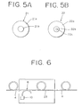
- the constructions of the upstream fiber 21 and the downstream fiber 22 are shown in Figs. 5A and 5B in cross section, respectively.
- the upstream fiber 21 is comprised of a clad 21a and a core 21b having a refractive index higher than that of the clad 21a. Er is doped in the core 21b with a uniform concentration distribution.
- the downstream fiber 22 is comprised of a clad 22a, a first core 22b and a second core 22c.
- a refractive index distribution in the first core 22b and the second core 22c of the downstream fiber 22 is the same as that in the core 21b of the upstream fiber 21.
- a refractive index of the clad 22a of the downstream fiber 22 is the same as that of the clad 21a of the upstream fiber 21.
- the second core 22c is formed at a central portion of the first core 22b, and Er is doped in the second core 22c only with a uniform concentration distribution.
- a method of doping a rare earth element in a specific portion of a core as in the downstream fiber 22 the following method may be adopted, for instance. That is, in producing a preform by an MCVD process, a first core glass not doped by a rare earth element is formed on an inner wall of a silica tube, and a second core glass doped with a rare earth element is formed on the first core glass.
- the two rare earth element doped fibers that is, the upstream fiber 21 and the downstream fiber 22 are used in this preferred embodiment
- a plurality (more than two) of rare earth element doped fibers formed with rare earth element doped portions having different diameters may be produced according to the above-mentioned method of producing the downstream fiber 22, and these rare earth element doped fibers may be connected together in series so that the diameters of the rare earth element doped portions becomes small in the direction of propagation of the pumping light.
- the concentration distribution of Er is uniform in the radial direction of the doped portion in this preferred embodiment, the concentration distribution of the rare earth element doped may be modified such that the concentration is high at the radially central area of the doped portion like the intensity distribution of the pumping light, so as to make the optical amplification efficient.
- the signal light from the input optical fiber 4 and the pumping light from the semiconductor laser 10 are coupled together by the optical coupler 8, and they are input into the upstream fiber 21.
- the signal light is amplified by the pumping light which has not yet been absorbed but has a sufficient intensity.
- the intensity of the pumping light becomes relatively small as the result of the amplification of the signal light. Then, the pumping light having a relatively small intensity and the amplified signal light are input into the downstream fiber 22.
- the optical amplification of the signal light can be efficiently carried out. Also in the case of applying this principle to an optical waveguide, the optical amplification can be similarly carried out by connecting in series a plurality of optical waveguide boards formed with Er doped optical waveguides having different widths.
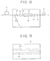
- Fig. 6 shows a construction of an optical fiber amplifier according to a second preferred embodiment of the present invention, in which the same parts as those in the first preferred embodiment are designated by the same reference numerals.
- a rare earth element doped fiber 23 is substituted for the upstream fiber 21 and the downstream fiber 22 used in the first preferred embodiment.
- the rare earth element doped fiber 23 is formed with a rare earth element doped portion having a diameter continuously changed. That is, the diameter of the rare earth element doped portion of the rare earth element doped fiber 23 is continuously reduced in the direction of propagation of the pumping light.
- the following method may be employed, for example. As shown in Fig.
- a rare earth element doped fiber 2 having a given length is heated at its substantially axially central portion by a burner 12, and is then extended in the opposite directions as depicted by arrows.
- a rare earth element doped fiber 2' as shown in Fig. 7B is formed.
- a diameter of the axially central portion of the rare earth element doped fiber 2' is smaller than that of the opposite end portions.
- the rare earth element doped fiber 2' is cut at the axially central portion to thereby obtain the rare earth element doped fiber 23 (extended fiber) formed with the Er doped portion having a diameter continuously reduced.
- elongated areas surrounded by dashed lines represent the Er doped portions of the rare earth element doped fibers 2 and 2'.
- the diameter of the rare earth element doped portion of the rare earth element doped fiber is continuously changed. Therefore, as compared with the first preferred embodiment wherein the diameter of the rare earth element doped portion is stepwise changed, the optical fiber amplifier according to the second preferred embodiment can further improve the amplification efficiency.
- the signal light and the pumping light are propagated in the same direction in the rare earth element doped fiber.
- the signal light and the pumping light may be propagated in the opposite directions in the rare earth element doped fiber.
- a signal light input from the input optical fiber 4 and a pumping light emitted from the semiconductor laser (LD) 10 are coupled together by the optical coupler 8. Then, the signal light and the pumping light thus coupled are condensed by a pair of lenses 25 and 26 to reach an optical waveguide 28 formed on an optical waveguide board 27. As shown in Fig. 9, an Er doped portion 29 is formed in the optical waveguide 28 so as to be gradually reduced in width in the direction of propagation of the pumping light.
- the formation of the Er doped portion 29 in the optical waveguide 28 as controlling the width of the Er doped portion 29 can be carried out by a thermomigration process, for example.
- the pumping light input into the optical waveguide 28 loses an energy upon excitation of Er in the optical waveguide 28 up to a high energy level, and a power of the pumping light is attenuated as propagating in the optical waveguide 28.
- the width of the Er doped portion 29 in the optical waveguide 28 is continuously reduced in concert with the attenuation of the power of the pumping light, absorption of the pumping light having an intensity not higher than a threshold by Er can be prevented.
- the amplified signal light After being amplified in the optical waveguide 28, the amplified signal light is condensed by a pair of lenses 30 and 31 to reach the output optical fiber 6.
- Fig. 10 shows a construction of an optical amplifier employing a rare earth element doped optical waveguide according to a fourth preferred embodiment of the present invention.
- an optical coupler 35 of a waveguide type is employed, so as to make a structure of the optical amplifier integratable. More specifically, an optical waveguide 33 for receiving a signal light from the input optical fiber 4 through the lenses 25 and 26 and an optical waveguide 34 for receiving a pumping light from the semiconductor laser (LD) 10 are formed on an optical waveguide board 32. The signal light and the pumping light propagated in the optical waveguides 33 and 34 are coupled together by the coupler 35, and they are then input into the Er doped optical waveguide 28 formed on the optical waveguide board 27. Both the optical waveguide boards 27 and 32 are bonded together by an optical adhesive or the like so as to align the waveguide of the coupler 35 to the waveguide 28.
- the present invention may be applied to the backward pumping such that the pumping light and the signal light are propagated in the opposite directions in the rare earth element doped optical waveguide.
- the diameter of the rare earth element doped portion of the rare earth element doped fiber is gradually reduced in the direction of propagation of the pumping light, an optical amplifier suitable for an increase in amplification efficiency can be provided.
- Such a feature can be similarly obtained by using the rare earth element doped optical waveguide.
- Such an increase in amplification enables the use of a semiconductor laser of a relatively low power as the pumping light source. Furthermore, in the case that the power of the semiconductor laser is fixed, a length of the rare earth element doped fiber to be employed can be reduced owing to the increase in amplification efficiency, thereby providing a compact optical amplifier.
Landscapes
- Physics & Mathematics (AREA)
- Electromagnetism (AREA)
- Engineering & Computer Science (AREA)
- Plasma & Fusion (AREA)
- Optics & Photonics (AREA)
- Lasers (AREA)
Abstract
Description
- The present invention relates to an optical amplifier employing a rare earth element doped fiber or a rare earth element doped optical waveguide doped with a rare earth element.
- In an optical communication system practically used at present, a repeater is inserted at fixed distance intervals, so as to compensate the attenuation of an optical signal due to a loss of an optical fiber. The repeater is constructed in such a manner that the optical signal is converted into an electrical signal by a photodiode to follow amplification of the electrical signal by means of an electronic amplifier, and thereafter the electrical signal thus amplified is converted into an optical signal by means of a semiconductor laser or the like to follow returning of the optical signal to an optical transmission line. If the optical signal can be directly amplified with a low noise as it stands, the optical repeater can be made compact and economized.
- In this circumstance, many researches in an optical amplifier capable of directly amplifying an optical signal have been greatly developed. The optical amplifier subjected to the researches is generally classified into (a) an optical amplifier employing, in combination, an optical fiber doped with a rare earth element (Er, Nb, Yb, etc.) and a pumping light; (b) an optical amplifier employing a semiconductor laser doped with the rare earth element; and (c) an optical amplifier utilizing a nonlinear effect in the optical fiber.
- Above all, the optical amplifier employing the combination of the rare earth element doped fiber and the pumping light as mentioned in the above type (a) has excellent features such as no polarization dependency, low noise, and small coupling loss to a transmission line. Accordingly, the optical amplifier of this type is expected to remarkably increase a repeating distance in an optical fiber transmission system, and it is also expected to enable multiple distributions of the optical signal.
- Fig. 1 shows the principle of the optical amplification by the rare earth element doped fiber. Referring to Fig. 1,
reference numeral 2 designates an optical fiber constructed of a core 2a and a clad 2b. Erbium (Er) is doped in the core 2a. When a pumping light is input into the Er dopedfiber 2, Er atoms are excited up to a high energy level. When a signal light is input into the Er atoms excited up to the high energy level in theoptical fiber 2, the Er atoms are shifted to a low energy level. At this time, stimulated emission of light is generated, and a power of the signal light is gradually increased along the optical fiber, thus effecting the amplification of the signal light. - In general, the concentration of Er doped in the core 2a is uniform with respect to a longitudinal direction and a radial direction of the Er doped
fiber 2. In the paper "Fabrication and Optimisation of the Erbium distribution in silica based doped fibers", presented at the 14th European Conference on Optical Communication, ECOC 88, 11. September 1988, London, B.J. Ainslie et al discussed an EP doped fiber with uniform doping distribution in the longitudinal direction but nonuniform distribution in the radial direction. - In accordance with the above-mentioned principle of the optical amplification, when the rare earth atoms in the rare earth element doped fiber are excited up to a high energy level by the pumping light, the energy of the pumping light is consumed. Therefore, as being propagated in the rare earth element doped fiber, the power of the pumping light is absorbed. Meanwhile, it is known that if the power of the pumping light is less than a certain threshold level, there does not occur the excitation of the rare earth atoms enough to effect the optical amplification. Accordingly, in the optical amplifier employing the rare earth element doped fiber doped with the rare earth element at a uniform concentration in the core, the doped rare earth element rather causes a power loss of the signal light and the pumping light. Therefore, the conventional optical amplifier having the above construction is considered to be unsuitable for an increase in amplification efficiency (i.e., a degree of amplification of the signal light with respect to the pumping light having a fixed power).
- It is accordingly an object of the present invention to provide an optical amplifier which can solve the above problem in the conventional technique and increase the amplification efficiency.
- According to one aspect of the present invention, there is provided an optical amplifier comprising a fiber doped with a rare earth element for amplifying a signal light by propagating the signal light and a pumping light in said fiber, characterized in that a diameter of a rare earth element doped portion of the rare earth element doped fiber is gradually reduced in a direction of propagation of the pumping light. The direction of propagation of the pumping light may be the same as or counter to a direction of propagation of the signal light.
- The gradual reduction of the diameter of the rare earth element doped portion in the direction of propagation of the pumping light is attained by extending the rare earth element doped fiber with heat to continuously change the diameter of the rare earth element doped portion. Alternatively, the gradual reduction of the diameter may be attained by connecting in series a plurality of rare earth element doped fibers formed with rare earth element doped portions having different diameters.
- According to another aspect of the present invention, there is provided an optical amplifier comprising an optical waveguide doped with a rare earth element for amplifying a signal light by propagating the signal light and a pumping light in said waveguide, characterized in that a width of a rare earth element doped portion of the rare earth element doped optical waveguide is gradually reduced in a direction of propagation of the pumping light.
-
- Fig. 1 is a schematic view-showing the principle of optical amplification by a rare earth element doped fiber;
- Figs. 2A and 2B are schematic views showing the principle of the present invention;
- Fig. 3 is a view explaining light intensity distributions at various points shown in Fig. 2A;
- Fig. 4 is an illustration of a construction of the optical amplifier according to a first preferred embodiment of the present invention;
- Figs. 5A and 5B are sectional views of an upstream fiber and a downstream fiber, respectively, shown in Fig. 4;
- Fig. 6 is an illustration of a construction of the optical amplifier according to a second preferred embodiment of the present invention;
- Figs. 7A and 7B are views explaining a manufacturing method of an extended fiber shown in Fig. 6;
- Fig. 8 is an illustration of a construction of the optical amplifier according to a third preferred embodiment of the present invention;
- Fig. 9 is an enlarged view of an optical waveguide shown in Fig. 8; and
- Fig. 10 is an illustration of a construction of the optical amplifier according to a fourth preferred embodiment of the present invention.
- There will first be described the principle of the present invention with reference to Figs. 2A and 2B. Fig. 2A shows a case that a signal light and a pumping light are propagated in the same direction in a rare earth element doped
fiber 2, and Fig. 2B shows a case that the signal light and the pumping light are propagated in the opposite directions in the rare earth element dopedfiber 2. - In an optical amplifier for amplifying the signal light by propagating the signal light and the pumping light in the rare earth element doped
fiber 2, a diameter of a rare earth element doped portion of the rare earth element dopedfiber 2 is gradually reduced in a direction of propagation of the pumping light as shown by dashed lines in Figs. 2A and 2B. - Whether the signal light and the pumping light are to be propagated in the same direction in the rare earth element doped
fiber 2, or the signal light and the pumping light are to be propagated in the opposite directions in the rare earth element dopedfiber 2 may be selected according to a construction of an optical communication system or the like to which the optical amplifier of the present invention is applied. - Referring to Fig. 2A, a point A denotes an upstream position of the direction of propagation of the signal light and the pumping light in the rare earth element doped
fiber 2; a point C denotes a downstream position of the direction of propagation; and a point B denotes an intermediate position between the points A and C. Referring to Fig. 3, graphs (A), (B) and (C) show the distributions of intensities of the pumping light at the points A, B and C shown in Fig. 2A, respectively. In each graph, an axis of ordinate represents an electric field amplitude of the pumping light, and an axis of abscissa represents a radial position in the rare earth element dopedfiber 2. - As apparent from Fig. 3, each graph gives a so-called Gaussian distribution such that the electric field amplitude of the pumping light at a central position of the
fiber 2 in the radial direction becomes high. Further, it is also understood that a maximum electric field amplitude of the pumping light is gradually reduced in the direction of propagation of the pumping light due to the fact that the rare earth atoms doped in thefiber 2 are excited by the pumping light. In Fig. 3, reference character Pth denotes a threshold level such that optical amplification is effected at levels higher than the threshold level Pth, while it is not effected at levels not higher than the threshold level Pth. Reference characters Ra, Rb and Rc denote radii of portions giving the electric field amplitude higher than the threshold level Pth at the points A, B and C, respectively. The relation among these radii is given as follows:
fiber 2 is gradually reduced in the direction of propagation of the pumping light. Accordingly, any adverse rare earth element doped portion which does not contribute to optical amplification but rather attenuates the pumping light as mentioned above with reference to Fig. 3 can be eliminated or reduced, thus providing an optical amplifier suitable for an increase in amplification efficiency. - Also in the case shown in Fig. 2B, i.e., in the case of so-called backward pumping such that the signal light and the pumping light are propagated in the opposite directions, the operation is similar to that in the case of so-called forward pumping shown in Fig. 2A.
- There will now be described a first preferred embodiment of the present invention.
- Fig. 4 shows a construction of an optical fiber amplifier according to the first preferred embodiment of the present invention. Referring to Fig. 4, a plurality of (two in this preferred embodiment) rare earth element doped
fibers fibers optical fiber 4 for propagating a signal light to be amplified and an outputoptical fiber 6 for propagating the signal light amplified are connected by splicing or the like to opposite ends of the rare earth element dopedfibers - An
optical coupler 8 of a fiber spliced type is formed at a midway portion of the inputoptical fiber 4 by splicing a side surface of another optical fiber to a side surface of the inputoptical fiber 4 and extending a spliced portion by heating. Theoptical coupler 8 includes a first input port 8a and afirst output port 8c on the way of the inputoptical fiber 4, and also includes asecond input port 8b and asecond output port 8d on the way of the another optical fiber. Asemiconductor laser 10 as a pumping light source is connected to thesecond input port 8b. - In the case that the doped rare earth element is erbium (Er), and a signal light having a wavelength of 1.55 µm band is intended to be amplified, a wavelength of the pumping light is selected to 0.80 µm band, 0.98 µm band, 1.48 µm band, etc. A structure parameter of the
optical coupler 8 is set so as to efficiently input the pumping light and the signal light thus selected into the rare earth element doped fiber, that is, so as to introduce substantially 100 % of the signal light input into the first input port 8a to thefirst output port 8c, and similarly introduce substantially 100 % of the pumping light input into thesecond input port 8b to thefirst output port 8c. - The rare earth element doped
fiber 21 located on the upstream side with respect to the direction of propagation of the signal light and the pumping light will be hereinafter referred to as anupstream fiber 21, and the rare earth element dopedfiber 22 located on the downstream side will be hereinafter referred to as adownstream fiber 22. The constructions of theupstream fiber 21 and thedownstream fiber 22 are shown in Figs. 5A and 5B in cross section, respectively. Theupstream fiber 21 is comprised of a clad 21a and a core 21b having a refractive index higher than that of the clad 21a. Er is doped in the core 21b with a uniform concentration distribution. Thedownstream fiber 22 is comprised of a clad 22a, afirst core 22b and a second core 22c. A refractive index distribution in thefirst core 22b and the second core 22c of thedownstream fiber 22 is the same as that in the core 21b of theupstream fiber 21. A refractive index of the clad 22a of thedownstream fiber 22 is the same as that of the clad 21a of theupstream fiber 21. - The second core 22c is formed at a central portion of the
first core 22b, and Er is doped in the second core 22c only with a uniform concentration distribution. As a method of doping a rare earth element in a specific portion of a core as in thedownstream fiber 22, the following method may be adopted, for instance. That is, in producing a preform by an MCVD process, a first core glass not doped by a rare earth element is formed on an inner wall of a silica tube, and a second core glass doped with a rare earth element is formed on the first core glass. - Although the two rare earth element doped fibers, that is, the
upstream fiber 21 and thedownstream fiber 22 are used in this preferred embodiment, a plurality (more than two) of rare earth element doped fibers formed with rare earth element doped portions having different diameters may be produced according to the above-mentioned method of producing thedownstream fiber 22, and these rare earth element doped fibers may be connected together in series so that the diameters of the rare earth element doped portions becomes small in the direction of propagation of the pumping light. Further, although the concentration distribution of Er is uniform in the radial direction of the doped portion in this preferred embodiment, the concentration distribution of the rare earth element doped may be modified such that the concentration is high at the radially central area of the doped portion like the intensity distribution of the pumping light, so as to make the optical amplification efficient. - In the optical fiber amplifier shown in Fig. 4, the signal light from the input
optical fiber 4 and the pumping light from thesemiconductor laser 10 are coupled together by theoptical coupler 8, and they are input into theupstream fiber 21. In theupstream fiber 21, the signal light is amplified by the pumping light which has not yet been absorbed but has a sufficient intensity. At the outlet of theupstream fiber 21, the intensity of the pumping light becomes relatively small as the result of the amplification of the signal light. Then, the pumping light having a relatively small intensity and the amplified signal light are input into thedownstream fiber 22. In thedownstream fiber 22, undesired absorption of the pumping light is not generated because the diameter of the Er doped second core 22c of thedownstream fiber 22 is smaller than the diameter of the core 21b of theupstream fiber 21. As a result, the optical amplification of the signal light can be efficiently carried out. Also in the case of applying this principle to an optical waveguide, the optical amplification can be similarly carried out by connecting in series a plurality of optical waveguide boards formed with Er doped optical waveguides having different widths. - Fig. 6 shows a construction of an optical fiber amplifier according to a second preferred embodiment of the present invention, in which the same parts as those in the first preferred embodiment are designated by the same reference numerals. Referring to Fig. 6, a rare earth element doped
fiber 23 is substituted for theupstream fiber 21 and thedownstream fiber 22 used in the first preferred embodiment. The rare earth element dopedfiber 23 is formed with a rare earth element doped portion having a diameter continuously changed. That is, the diameter of the rare earth element doped portion of the rare earth element dopedfiber 23 is continuously reduced in the direction of propagation of the pumping light. As a method of continuously reducing the diameter of the rare earth element doped portion, the following method may be employed, for example. As shown in Fig. 7A, a rare earth element dopedfiber 2 having a given length is heated at its substantially axially central portion by aburner 12, and is then extended in the opposite directions as depicted by arrows. As a result, a rare earth element doped fiber 2' as shown in Fig. 7B is formed. As apparent from Fig. 7B, a diameter of the axially central portion of the rare earth element doped fiber 2' is smaller than that of the opposite end portions. Then, the rare earth element doped fiber 2' is cut at the axially central portion to thereby obtain the rare earth element doped fiber 23 (extended fiber) formed with the Er doped portion having a diameter continuously reduced. In Figs. 7A and 7B, elongated areas surrounded by dashed lines represent the Er doped portions of the rare earth element dopedfibers 2 and 2'. - According to the second preferred embodiment, the diameter of the rare earth element doped portion of the rare earth element doped fiber is continuously changed. Therefore, as compared with the first preferred embodiment wherein the diameter of the rare earth element doped portion is stepwise changed, the optical fiber amplifier according to the second preferred embodiment can further improve the amplification efficiency.
- In the first and second preferred embodiments as described above, the signal light and the pumping light are propagated in the same direction in the rare earth element doped fiber. However, the signal light and the pumping light may be propagated in the opposite directions in the rare earth element doped fiber.
- There will now be described a third preferred embodiment of the present invention with reference to Fig. 8 employing a rare earth element doped optical waveguide which is doped with a rare earth element such as Er. Referring to Fig. 8, a signal light input from the input
optical fiber 4 and a pumping light emitted from the semiconductor laser (LD) 10 are coupled together by theoptical coupler 8. Then, the signal light and the pumping light thus coupled are condensed by a pair oflenses optical waveguide 28 formed on anoptical waveguide board 27. As shown in Fig. 9, an Erdoped portion 29 is formed in theoptical waveguide 28 so as to be gradually reduced in width in the direction of propagation of the pumping light. The formation of the Er dopedportion 29 in theoptical waveguide 28 as controlling the width of the Er dopedportion 29 can be carried out by a thermomigration process, for example. In this preferred embodiment, the pumping light input into theoptical waveguide 28 loses an energy upon excitation of Er in theoptical waveguide 28 up to a high energy level, and a power of the pumping light is attenuated as propagating in theoptical waveguide 28. According to this preferred embodiment, since the width of the Er dopedportion 29 in theoptical waveguide 28 is continuously reduced in concert with the attenuation of the power of the pumping light, absorption of the pumping light having an intensity not higher than a threshold by Er can be prevented. After being amplified in theoptical waveguide 28, the amplified signal light is condensed by a pair oflenses optical fiber 6. - Fig. 10 shows a construction of an optical amplifier employing a rare earth element doped optical waveguide according to a fourth preferred embodiment of the present invention. Referring to Fig. 10, an
optical coupler 35 of a waveguide type is employed, so as to make a structure of the optical amplifier integratable. More specifically, anoptical waveguide 33 for receiving a signal light from the inputoptical fiber 4 through thelenses optical waveguide 34 for receiving a pumping light from the semiconductor laser (LD) 10 are formed on anoptical waveguide board 32. The signal light and the pumping light propagated in theoptical waveguides coupler 35, and they are then input into the Er dopedoptical waveguide 28 formed on theoptical waveguide board 27. Both theoptical waveguide boards coupler 35 to thewaveguide 28. - Although the third and fourth preferred embodiments shown in Figs. 8 and 10 have been directed to the forward pumping such that the pumping light and the signal light are propagated in the same direction in the rare earth element doped optical waveguide, the present invention may be applied to the backward pumping such that the pumping light and the signal light are propagated in the opposite directions in the rare earth element doped optical waveguide.
- According to the present invention as described above, since the diameter of the rare earth element doped portion of the rare earth element doped fiber is gradually reduced in the direction of propagation of the pumping light, an optical amplifier suitable for an increase in amplification efficiency can be provided. Such a feature can be similarly obtained by using the rare earth element doped optical waveguide.
- Such an increase in amplification enables the use of a semiconductor laser of a relatively low power as the pumping light source. Furthermore, in the case that the power of the semiconductor laser is fixed, a length of the rare earth element doped fiber to be employed can be reduced owing to the increase in amplification efficiency, thereby providing a compact optical amplifier.
Claims (9)
- An optical amplifier comprising a fiber (2) doped with a rare earth element for amplifying a signal light by propagating said signal light and a pumping light in said fiber, characterized in that the diameter of a rare earth element doped portion of said rare earth element doped fiber is gradually reduced in a direction of propagation of said said pumping light.
- The optical amplifier as defined in claim 1, wherein said signal light and said pumping light are propagated in the same direction in said rare earth element doped fiber (2).
- The optical amplifier as defined in claim 1, wherein said signal light and said pumping light are propagated in the opposite directions in said rare earth element doped fiber (2).
- The optical amplifier as defined in claim 1, wherein said rare earth element doped fiber (2) comprises a plurality of rare earth element doped fibers (21,22) connected together in series, said plural rare earth element doped fibers being formed with rare earth element doped portions having different diameters (21b,22c).
- The optical amplifier as defined in claim 1, wherein the rare earth element doped portion has a biconical taper (2') formed by heating and drawing of said fiber (2).
- An optical amplifier comprising an optical waveguide (28) doped with a rare earth element for amplifying a signal light by propagating said signal light and a pumping light in said waveguide, characterized in that the width of a rare earth element doped portion (29) of said rare earth element doped optical waveguide is gradually reduced in a direction of propagation of said said pumping light.
- The optical amplifier as defined in claim 6, wherein said signal light and said pumping light are propagated in the same direction in said rare earth element doped optical waveguide (28).
- The optical amplifier as defined in claim 6, wherein said signal light and said pumping light are propagated in the opposite directions in said rare earth element doped optical waveguide(28).
- The optical amplifier as defined in claim 6, wherein said rare earth element doped optical waveguide (28) comprises a plurality of rare earth element doped optical waveguides connected together in series, said plural rare earth element doped optical waveguides being formed with rare earth element doped portions having different widths.
Applications Claiming Priority (3)
| Application Number | Priority Date | Filing Date | Title |
|---|---|---|---|
| JP29971289 | 1989-11-20 | ||
| JP299712/89 | 1989-11-20 | ||
| PCT/JP1990/001499 WO1991007690A1 (en) | 1989-11-20 | 1990-11-16 | Optical amplifier |
Publications (3)
| Publication Number | Publication Date |
|---|---|
| EP0454865A1 EP0454865A1 (en) | 1991-11-06 |
| EP0454865A4 EP0454865A4 (en) | 1993-04-21 |
| EP0454865B1 true EP0454865B1 (en) | 1996-05-01 |
Family
ID=17876054
Family Applications (1)
| Application Number | Title | Priority Date | Filing Date |
|---|---|---|---|
| EP90916809A Expired - Lifetime EP0454865B1 (en) | 1989-11-20 | 1990-11-16 | Optical amplifier |
Country Status (5)
| Country | Link |
|---|---|
| US (1) | US5508842A (en) |
| EP (1) | EP0454865B1 (en) |
| CA (1) | CA2042578C (en) |
| DE (1) | DE69026815T2 (en) |
| WO (1) | WO1991007690A1 (en) |
Families Citing this family (20)
| Publication number | Priority date | Publication date | Assignee | Title |
|---|---|---|---|---|
| DE69026815T2 (en) * | 1989-11-20 | 1996-09-19 | Fujitsu Ltd | OPTICAL AMPLIFIER |
| US5131069A (en) * | 1991-08-12 | 1992-07-14 | Corning Incorporated | Fiber amplifier having modified gain spectrum |
| US5321711A (en) * | 1992-08-17 | 1994-06-14 | Alliedsignal Inc. | Segmented solid state laser gain media with gradient doping level |
| DE4430512C2 (en) * | 1994-08-27 | 2000-06-29 | Bosch Gmbh Robert | Device for connecting a reinforcing fiber |
| US7576909B2 (en) * | 1998-07-16 | 2009-08-18 | Imra America, Inc. | Multimode amplifier for amplifying single mode light |
| US6937636B1 (en) * | 1999-09-27 | 2005-08-30 | The Regents Of The University Of California | Tapered laser rods as a means of minimizing the path length of trapped barrel mode rays |
| GB9928696D0 (en) * | 1999-12-03 | 2000-02-02 | Swan Thomas & Co Ltd | Optical devices and methods of manufacture thereof |
| US6411757B1 (en) * | 2000-02-14 | 2002-06-25 | Agere Systems Guardian Corp. | Article comprising a waveguide structure with improved pump utilization |
| DE10009379C2 (en) * | 2000-02-29 | 2002-04-25 | Schneider Laser Technologies | Fiber optic amplifier |
| FR2830376B1 (en) * | 2001-10-01 | 2010-11-05 | Teem Photonics | HYBRID OPTICAL AMPLIFIER AND MATRIX OF SUCH AMPLIFIERS |
| DE10203392B4 (en) * | 2002-01-29 | 2014-09-04 | Osram Opto Semiconductors Gmbh | Arrangement for coupling radiation into an optical fiber |
| WO2004075364A1 (en) * | 2003-02-21 | 2004-09-02 | Fujitsu Limited | Optical amplifier employing delay phase matching fiber |
| US7557986B2 (en) * | 2004-05-13 | 2009-07-07 | Soreq Nuclear Research Center | High power fiber amplifier |
| US7768700B1 (en) | 2006-11-30 | 2010-08-03 | Lockheed Martin Corporation | Method and apparatus for optical gain fiber having segments of differing core sizes |
| JP2009059924A (en) * | 2007-08-31 | 2009-03-19 | Sunx Ltd | Laser generating device and laser machining device |
| US9214781B2 (en) | 2013-11-21 | 2015-12-15 | Lockheed Martin Corporation | Fiber amplifier system for suppression of modal instabilities and method |
| US10156675B1 (en) * | 2014-08-27 | 2018-12-18 | Bae Systems Information And Electronic Systems Integration Inc. | Method and apparatus for the modulation of pump absorption in a clad optical fiber that is used in lasers and amplifiers |
| CN110323659A (en) | 2018-03-30 | 2019-10-11 | 株式会社藤仓 | Amplification optical fiber, fiber laser device and optical resonator |
| US11175449B2 (en) * | 2019-01-02 | 2021-11-16 | Lumentum Operations Llc | Optical fiber with variable absorption |
| US11808970B2 (en) | 2019-01-02 | 2023-11-07 | Lumentum Operations Llc | Optical fiber with variable absorption |
Citations (1)
| Publication number | Priority date | Publication date | Assignee | Title |
|---|---|---|---|---|
| JPH06114624A (en) * | 1992-10-01 | 1994-04-26 | Asama Giken Kogyo Kk | Key seat cutting broach and key seat making device fitted with broach |
Family Cites Families (12)
| Publication number | Priority date | Publication date | Assignee | Title |
|---|---|---|---|---|
| US4161944A (en) * | 1976-09-17 | 1979-07-24 | Muckerheide Myron C | Laser system and method and laser amplifier for use therewith |
| US4554510A (en) * | 1983-09-12 | 1985-11-19 | The Board Of Trustees Of Leland Stanford Junior University | Switching fiber optic amplifier |
| US5048026A (en) * | 1983-09-30 | 1991-09-10 | The Board Of Trustees Of The Leland Stanford Junior University | Fiber optic amplifier |
| JPS6114624A (en) * | 1984-06-29 | 1986-01-22 | Nippon Telegr & Teleph Corp <Ntt> | Optical amplifying device by optical fiber |
| US4739507A (en) * | 1984-11-26 | 1988-04-19 | Board Of Trustees, Stanford University | Diode end pumped laser and harmonic generator using same |
| US4653056A (en) * | 1985-05-01 | 1987-03-24 | Spectra-Physics, Inc. | Nd-YAG laser |
| AU607895B2 (en) * | 1985-08-13 | 1991-03-21 | Robert Joseph Mears | Fibre-optic lasers and amplifiers |
| US4941726A (en) * | 1988-08-31 | 1990-07-17 | The Unites States Of America As Represented By The Secretary Of The Navy | Tapered fiber amplifier |
| US4867518A (en) * | 1988-08-31 | 1989-09-19 | The United States Of America As Represented By The Secretary Of The Navy | All-fiber SFPM amplifier |
| JPH0373934A (en) * | 1989-08-15 | 1991-03-28 | Fujitsu Ltd | Optical amplifier |
| US5058974A (en) * | 1989-10-06 | 1991-10-22 | At&T Bell Laboratories | Distributed amplification for lightwave transmission system |
| DE69026815T2 (en) * | 1989-11-20 | 1996-09-19 | Fujitsu Ltd | OPTICAL AMPLIFIER |
-
1990
- 1990-11-16 DE DE69026815T patent/DE69026815T2/en not_active Expired - Fee Related
- 1990-11-16 EP EP90916809A patent/EP0454865B1/en not_active Expired - Lifetime
- 1990-11-16 CA CA002042578A patent/CA2042578C/en not_active Expired - Fee Related
- 1990-11-16 WO PCT/JP1990/001499 patent/WO1991007690A1/en active IP Right Grant
-
1994
- 1994-06-13 US US08/259,133 patent/US5508842A/en not_active Expired - Lifetime
Patent Citations (1)
| Publication number | Priority date | Publication date | Assignee | Title |
|---|---|---|---|---|
| JPH06114624A (en) * | 1992-10-01 | 1994-04-26 | Asama Giken Kogyo Kk | Key seat cutting broach and key seat making device fitted with broach |
Also Published As
| Publication number | Publication date |
|---|---|
| US5508842A (en) | 1996-04-16 |
| WO1991007690A1 (en) | 1991-05-30 |
| DE69026815D1 (en) | 1996-06-05 |
| EP0454865A4 (en) | 1993-04-21 |
| DE69026815T2 (en) | 1996-09-19 |
| EP0454865A1 (en) | 1991-11-06 |
| CA2042578C (en) | 1995-04-04 |
Similar Documents
| Publication | Publication Date | Title |
|---|---|---|
| EP0454865B1 (en) | Optical amplifier | |
| EP1935068B1 (en) | Optical fibre laser | |
| USRE38298E1 (en) | Double-core active fiber optical amplifier having a wide-band signal wavelength | |
| JP3987840B2 (en) | Cladding pump optical fiber gain device | |
| KR101750861B1 (en) | Multimode fiber | |
| US5768012A (en) | Apparatus and method for the high-power pumping of fiber optic amplifiers | |
| KR100900793B1 (en) | Gain clamped amplifier using double clad fiber | |
| JP2008276233A (en) | Mode-field resizing in optical fiber | |
| US20090041415A1 (en) | Double-core optical fiber | |
| JPH0580230A (en) | Fiber optic-filter structure | |
| JP4959314B2 (en) | Rare earth doped large mode area multimode optical fiber and device using the same | |
| US5416864A (en) | Optical fiber amplified tapping network and method using same | |
| US5706124A (en) | Rare earth element-doped optical fiber amplifier | |
| US20040179797A1 (en) | Multi-wavelength optical fiber | |
| EP1126566B1 (en) | Optical waveguide structure | |
| RU2096914C1 (en) | Fiber-optic communication line and its amplifier | |
| JP3942654B2 (en) | Optical amplifier using doped fluoride glass optical fiber and manufacturing method thereof | |
| JP4032648B2 (en) | Optical fiber amplifier and optical fiber used therefor | |
| JPH10242548A (en) | Er added multicore fiber and light amplifier using the same | |
| JP2955780B2 (en) | Optical fiber amplifier | |
| JP2842481B2 (en) | Optical amplifier | |
| EP0926519B1 (en) | Optical fiber coupler, method for producing the same and optical amplifier using the same | |
| JP2884919B2 (en) | Rare earth element doped multi-core fiber coupler | |
| JP2002359419A (en) | Optical fiber coupler and optical amplifier using the same | |
| JP2818365B2 (en) | Active optical fiber coupler and method of manufacturing the same |
Legal Events
| Date | Code | Title | Description |
|---|---|---|---|
| PUAI | Public reference made under article 153(3) epc to a published international application that has entered the european phase |
Free format text: ORIGINAL CODE: 0009012 |
|
| 17P | Request for examination filed |
Effective date: 19910626 |
|
| AK | Designated contracting states |
Kind code of ref document: A1 Designated state(s): DE FR GB |
|
| A4 | Supplementary search report drawn up and despatched |
Effective date: 19920301 |
|
| AK | Designated contracting states |
Kind code of ref document: A4 Designated state(s): DE FR GB |
|
| 17Q | First examination report despatched |
Effective date: 19950718 |
|
| GRAA | (expected) grant |
Free format text: ORIGINAL CODE: 0009210 |
|
| AK | Designated contracting states |
Kind code of ref document: B1 Designated state(s): DE FR GB |
|
| REF | Corresponds to: |
Ref document number: 69026815 Country of ref document: DE Date of ref document: 19960605 |
|
| GRAH | Despatch of communication of intention to grant a patent |
Free format text: ORIGINAL CODE: EPIDOS IGRA |
|
| ET | Fr: translation filed | ||
| PLBE | No opposition filed within time limit |
Free format text: ORIGINAL CODE: 0009261 |
|
| STAA | Information on the status of an ep patent application or granted ep patent |
Free format text: STATUS: NO OPPOSITION FILED WITHIN TIME LIMIT |
|
| 26N | No opposition filed | ||
| REG | Reference to a national code |
Ref country code: GB Ref legal event code: IF02 |
|
| PGFP | Annual fee paid to national office [announced via postgrant information from national office to epo] |
Ref country code: FR Payment date: 20041109 Year of fee payment: 15 |
|
| PGFP | Annual fee paid to national office [announced via postgrant information from national office to epo] |
Ref country code: GB Payment date: 20041110 Year of fee payment: 15 |
|
| PGFP | Annual fee paid to national office [announced via postgrant information from national office to epo] |
Ref country code: DE Payment date: 20041111 Year of fee payment: 15 |
|
| PG25 | Lapsed in a contracting state [announced via postgrant information from national office to epo] |
Ref country code: GB Free format text: LAPSE BECAUSE OF NON-PAYMENT OF DUE FEES Effective date: 20051116 |
|
| PG25 | Lapsed in a contracting state [announced via postgrant information from national office to epo] |
Ref country code: DE Free format text: LAPSE BECAUSE OF NON-PAYMENT OF DUE FEES Effective date: 20060601 |
|
| GBPC | Gb: european patent ceased through non-payment of renewal fee |
Effective date: 20051116 |
|
| PG25 | Lapsed in a contracting state [announced via postgrant information from national office to epo] |
Ref country code: FR Free format text: LAPSE BECAUSE OF NON-PAYMENT OF DUE FEES Effective date: 20060731 |
|
| REG | Reference to a national code |
Ref country code: FR Ref legal event code: ST Effective date: 20060731 |