EP0269536B1 - Moteur à explosion sans embiellage ni vilebrequin de type cylindres en étoile - Google Patents
Moteur à explosion sans embiellage ni vilebrequin de type cylindres en étoile Download PDFInfo
- Publication number
- EP0269536B1 EP0269536B1 EP87420314A EP87420314A EP0269536B1 EP 0269536 B1 EP0269536 B1 EP 0269536B1 EP 87420314 A EP87420314 A EP 87420314A EP 87420314 A EP87420314 A EP 87420314A EP 0269536 B1 EP0269536 B1 EP 0269536B1
- Authority
- EP
- European Patent Office
- Prior art keywords
- cams
- engine according
- cylinders
- cam
- radial engine
- Prior art date
- Legal status (The legal status is an assumption and is not a legal conclusion. Google has not performed a legal analysis and makes no representation as to the accuracy of the status listed.)
- Expired - Lifetime
Links
- 238000002485 combustion reaction Methods 0.000 title claims description 19
- 230000006835 compression Effects 0.000 claims description 10
- 238000007906 compression Methods 0.000 claims description 10
- 238000005096 rolling process Methods 0.000 claims description 2
- 238000006073 displacement reaction Methods 0.000 claims 1
- 230000001737 promoting effect Effects 0.000 claims 1
- 238000004880 explosion Methods 0.000 description 5
- 240000008042 Zea mays Species 0.000 description 2
- 230000005540 biological transmission Effects 0.000 description 2
- 238000010276 construction Methods 0.000 description 2
- 239000007789 gas Substances 0.000 description 2
- 238000002347 injection Methods 0.000 description 1
- 239000007924 injection Substances 0.000 description 1
- 230000000284 resting effect Effects 0.000 description 1
- 239000000243 solution Substances 0.000 description 1
Images


Classifications
-
- F—MECHANICAL ENGINEERING; LIGHTING; HEATING; WEAPONS; BLASTING
- F01—MACHINES OR ENGINES IN GENERAL; ENGINE PLANTS IN GENERAL; STEAM ENGINES
- F01B—MACHINES OR ENGINES, IN GENERAL OR OF POSITIVE-DISPLACEMENT TYPE, e.g. STEAM ENGINES
- F01B1/00—Reciprocating-piston machines or engines characterised by number or relative disposition of cylinders or by being built-up from separate cylinder-crankcase elements
- F01B1/06—Reciprocating-piston machines or engines characterised by number or relative disposition of cylinders or by being built-up from separate cylinder-crankcase elements with cylinders in star or fan arrangement
- F01B1/0641—Details, component parts specially adapted for such machines
- F01B1/0648—Cams
-
- F—MECHANICAL ENGINEERING; LIGHTING; HEATING; WEAPONS; BLASTING
- F01—MACHINES OR ENGINES IN GENERAL; ENGINE PLANTS IN GENERAL; STEAM ENGINES
- F01B—MACHINES OR ENGINES, IN GENERAL OR OF POSITIVE-DISPLACEMENT TYPE, e.g. STEAM ENGINES
- F01B9/00—Reciprocating-piston machines or engines characterised by connections between pistons and main shafts and not specific to preceding groups
- F01B9/04—Reciprocating-piston machines or engines characterised by connections between pistons and main shafts and not specific to preceding groups with rotary main shaft other than crankshaft
- F01B9/06—Reciprocating-piston machines or engines characterised by connections between pistons and main shafts and not specific to preceding groups with rotary main shaft other than crankshaft the piston motion being transmitted by curved surfaces
-
- F—MECHANICAL ENGINEERING; LIGHTING; HEATING; WEAPONS; BLASTING
- F02—COMBUSTION ENGINES; HOT-GAS OR COMBUSTION-PRODUCT ENGINE PLANTS
- F02B—INTERNAL-COMBUSTION PISTON ENGINES; COMBUSTION ENGINES IN GENERAL
- F02B75/00—Other engines
- F02B75/02—Engines characterised by their cycles, e.g. six-stroke
-
- F—MECHANICAL ENGINEERING; LIGHTING; HEATING; WEAPONS; BLASTING
- F02—COMBUSTION ENGINES; HOT-GAS OR COMBUSTION-PRODUCT ENGINE PLANTS
- F02B—INTERNAL-COMBUSTION PISTON ENGINES; COMBUSTION ENGINES IN GENERAL
- F02B75/00—Other engines
- F02B75/16—Engines characterised by number of cylinders, e.g. single-cylinder engines
- F02B75/18—Multi-cylinder engines
- F02B75/22—Multi-cylinder engines with cylinders in V, fan, or star arrangement
- F02B75/222—Multi-cylinder engines with cylinders in V, fan, or star arrangement with cylinders in star arrangement
-
- F—MECHANICAL ENGINEERING; LIGHTING; HEATING; WEAPONS; BLASTING
- F02—COMBUSTION ENGINES; HOT-GAS OR COMBUSTION-PRODUCT ENGINE PLANTS
- F02B—INTERNAL-COMBUSTION PISTON ENGINES; COMBUSTION ENGINES IN GENERAL
- F02B75/00—Other engines
- F02B75/32—Engines characterised by connections between pistons and main shafts and not specific to preceding main groups
-
- F—MECHANICAL ENGINEERING; LIGHTING; HEATING; WEAPONS; BLASTING
- F01—MACHINES OR ENGINES IN GENERAL; ENGINE PLANTS IN GENERAL; STEAM ENGINES
- F01B—MACHINES OR ENGINES, IN GENERAL OR OF POSITIVE-DISPLACEMENT TYPE, e.g. STEAM ENGINES
- F01B9/00—Reciprocating-piston machines or engines characterised by connections between pistons and main shafts and not specific to preceding groups
- F01B9/04—Reciprocating-piston machines or engines characterised by connections between pistons and main shafts and not specific to preceding groups with rotary main shaft other than crankshaft
- F01B9/06—Reciprocating-piston machines or engines characterised by connections between pistons and main shafts and not specific to preceding groups with rotary main shaft other than crankshaft the piston motion being transmitted by curved surfaces
- F01B2009/061—Reciprocating-piston machines or engines characterised by connections between pistons and main shafts and not specific to preceding groups with rotary main shaft other than crankshaft the piston motion being transmitted by curved surfaces by cams
- F01B2009/063—Mono-lobe cams
-
- F—MECHANICAL ENGINEERING; LIGHTING; HEATING; WEAPONS; BLASTING
- F01—MACHINES OR ENGINES IN GENERAL; ENGINE PLANTS IN GENERAL; STEAM ENGINES
- F01B—MACHINES OR ENGINES, IN GENERAL OR OF POSITIVE-DISPLACEMENT TYPE, e.g. STEAM ENGINES
- F01B9/00—Reciprocating-piston machines or engines characterised by connections between pistons and main shafts and not specific to preceding groups
- F01B9/04—Reciprocating-piston machines or engines characterised by connections between pistons and main shafts and not specific to preceding groups with rotary main shaft other than crankshaft
- F01B9/06—Reciprocating-piston machines or engines characterised by connections between pistons and main shafts and not specific to preceding groups with rotary main shaft other than crankshaft the piston motion being transmitted by curved surfaces
- F01B2009/061—Reciprocating-piston machines or engines characterised by connections between pistons and main shafts and not specific to preceding groups with rotary main shaft other than crankshaft the piston motion being transmitted by curved surfaces by cams
- F01B2009/065—Bi-lobe cams
-
- F—MECHANICAL ENGINEERING; LIGHTING; HEATING; WEAPONS; BLASTING
- F01—MACHINES OR ENGINES IN GENERAL; ENGINE PLANTS IN GENERAL; STEAM ENGINES
- F01B—MACHINES OR ENGINES, IN GENERAL OR OF POSITIVE-DISPLACEMENT TYPE, e.g. STEAM ENGINES
- F01B9/00—Reciprocating-piston machines or engines characterised by connections between pistons and main shafts and not specific to preceding groups
- F01B9/04—Reciprocating-piston machines or engines characterised by connections between pistons and main shafts and not specific to preceding groups with rotary main shaft other than crankshaft
- F01B9/06—Reciprocating-piston machines or engines characterised by connections between pistons and main shafts and not specific to preceding groups with rotary main shaft other than crankshaft the piston motion being transmitted by curved surfaces
- F01B2009/061—Reciprocating-piston machines or engines characterised by connections between pistons and main shafts and not specific to preceding groups with rotary main shaft other than crankshaft the piston motion being transmitted by curved surfaces by cams
- F01B2009/066—Tri-lobe cams
-
- F—MECHANICAL ENGINEERING; LIGHTING; HEATING; WEAPONS; BLASTING
- F02—COMBUSTION ENGINES; HOT-GAS OR COMBUSTION-PRODUCT ENGINE PLANTS
- F02B—INTERNAL-COMBUSTION PISTON ENGINES; COMBUSTION ENGINES IN GENERAL
- F02B75/00—Other engines
- F02B75/02—Engines characterised by their cycles, e.g. six-stroke
- F02B2075/022—Engines characterised by their cycles, e.g. six-stroke having less than six strokes per cycle
- F02B2075/027—Engines characterised by their cycles, e.g. six-stroke having less than six strokes per cycle four
-
- F—MECHANICAL ENGINEERING; LIGHTING; HEATING; WEAPONS; BLASTING
- F02—COMBUSTION ENGINES; HOT-GAS OR COMBUSTION-PRODUCT ENGINE PLANTS
- F02B—INTERNAL-COMBUSTION PISTON ENGINES; COMBUSTION ENGINES IN GENERAL
- F02B75/00—Other engines
- F02B75/16—Engines characterised by number of cylinders, e.g. single-cylinder engines
- F02B75/18—Multi-cylinder engines
- F02B2075/1804—Number of cylinders
- F02B2075/1816—Number of cylinders four
Definitions
- the motor according to the invention is characterized in that the three cams have an external cam contour which cooperates with said rollers and are mounted side by side on the motor shaft, the central cam rotating in one direction and the two lateral cams rotating at the same speed as the central cam but in the opposite direction to the latter, the three cams being positioned so that the tops of the bosses of the three cams in top dead center are in a plane passing through the axis of the motor shaft and the three peaks of said bosses, the ends of said axis of the rollers being guided in grooves formed in the external extension of the side cams.
- the reversal of the central cam or of the two lateral cams is effected either by means of a Pecking train, or by means of pinions integral with the walls of the engine, or by means of a spherical train.
- connecting pieces or cables connect the pistons of the opposite cylinders when the movement of the two pistons is identical and in the same direction.
- it comprises on each side of a row of cylinders, two concentric drive shafts but rotating in opposite directions.
- one or more cams may include mini-bosses intended to control the opening of the engine valves.
- it comprises on one side of several rows of cylinders, twice the number of drive shafts that there are rows of cylinders plus one.
- each piston will have only one roller.
- the combustion piston is arranged so that it achieves on the one hand the combustion in its upper part and, on the other hand, the compression in its lower part thus making it possible to achieve compression .
- the layout of the cams of the star engine is produced so that the top of the bosses bring the piston to top dead center then lower it slightly and bring it back to top dead center so as to promote combustion.
- combustion takes place at a constant volume for a time substantially equal to other times such as compression, explosion and expansion.
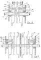
- FIG. 1 shows a sectional view of an engine where a single cylinder has been shown.
- the motor shaft (1) integral with the central cam (2), with the two lateral cams (3) and (4).
- the rollers (5, 6, 7) are supported, integral with the piston (8) which moves in the cylinder (9) terminated by the cylinder head (10).
- the engine block (11) carries the engine shaft (1).
- the two lateral cams (3) and (4) rotate in the opposite direction to the central cam (2) thanks to a train of planetary gears known as the Pecker train, the motor shaft (1) drives the central gears (13) which drive the satellites (15) and (14) integral with the cams (3) and (4).
- this groove (18) can be eliminated to replace it with parts which may be cables uniting the opposite pistons (8).
- Fixed gears or spherical gears can be used instead of planetary gears, in order to obtain an equal and opposite direction of speed.
- the profile of the central cam is by symmetrical construction of the profile of the side cams in order to be able to rotate and hold the rollers of the piston.
- Figure 2 is a front sectional view showing a central cam and a side cam having two bosses (12).
- the mini-bosses (19) allow the engine intake and exhaust valves to be lifted.
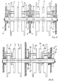
- FIG. 3 is a transverse view of an engine with a single row of cylinders and two concentric drive shafts rotating at equal speed but in opposite directions, only the upper part having been shown.
- the motor shaft (1) integral with the central cam (2), the side cams (3) and (4) rotate in opposite directions and at equal speed from the central cam (2) thanks to the pinions (13,14,15, 16) but the arrangement of the cam (4) is a little different, the pinion (13) integral with the motor shaft (1) being placed between the cams (2) and (4), it attacks the pinion (14) integral with the pinion (15) located on the other side of the cam (4), which rests on the fixed pinion (16).
- a second driving shaft (20) is obtained which is counter-rotating of the shaft (1
- Figure 4 is a cross-sectional view of an engine having two rows of cylinders with a single engine shaft (1); there are the housing (11) assembled with the housing (21) to form a single block, there are the same cams (2, 3, 4) and the same pinions (13,14,15 and 16).
- it is the side cams (3) and (4) which are integral with the motor shaft (1) and it is the central cam (2) which is driven in reverse and at equal speed by the train. Fisherman (13, 14, 15, 16). So there is only one output shaft.
- the drive shaft (1) always carrying the three cams (2, 3, 4), but in this case, it is the central cam which is integral with the drive shaft.
- the motor shaft integral with either the central cam or the two side cams without departing from the scope of the invention.
- a new Pécqueur train comprising a pinion (25) integral with the motor shaft (1) drives the satellite (26, 27) which rests on the fixed pinion (28).
- the cam (23) goes in reverse and at equal speed if the pinions have the desired number of teeth.
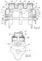
- FIG. 7 is a cross-sectional view showing the particular case of an engine where there are three rows of cylinders, each row having only one cam, but the engine shaft of which always carries three cams, one central cam rotating in one direction and two side cams turning in opposite direction and at equal speed.
- the motor shaft (1) carries a central cam (2) integral for example with the motor shaft, the cams (3) and (4) rotating in opposite directions and at equal speed thanks to the pinions of a Pecqueur train (13 , 14, 15, 16).
- the three pistons (8) are integral with the rollers (5, 6, 7) which are mounted on a single axis (17) which comes to rest in the groove (18) via the roller (30), the cylinders (9) carrying the cylinder heads (10).
- the three pistons will therefore work at the same time, so a lighter construction is obtained if one seeks to obtain a greater number of cylinders, moreover the pistons will be able to carry bearing surfaces substantially at the height of the roller, to support the slight deformation of the axis (17), these bearing surfaces being located in the axis of the cam.
- Figure 8 is a front sectional view showing a central cam (2) with its drive shaft (1) and its roller (5) journalled on its axis (17).
- This roller is attached to the piston (8) which consists of two parts, the upper part includes the cylinder (9), the cylinder head (10) and the combustion chamber (31) in the lower part, which can be of a diameter more important.
- the bottom of the piston (8) compressing the space (32) to provide a supply of compressed air to the engine, a very simple compressor is thus produced.
- intake and exhaust ducts and valves will allow the compressed air to reach the cylinder head (10), but this is not part of the invention and has therefore not been shown.
- Figure 9 is a front sectional view showing a cam with a single boss.
- the motor shaft (1) driving the cam (2) we find the motor shaft (1) driving the cam (2), the piston reaches top dead center at point (33) then it descends to point (35) and goes back to top dead center (34).
- the cam (2) receives the thrust resulting from combustion, it is the trigger, at point (36) the piston is in bottom dead center, it stays there until at point (37), which allows the exhaust of the burnt gases and the introduction of fresh gases, at point (37) the piston begins its compression which it completes at point (33). It is a little before point (33) that the injection or ignition of the spark plug begins.
- Figure 10 is a schematic view showing the different times of a cycle comprising an engine time for two round trips and pistons (like four times).
- points (36) and (37) would be confused with point (38), and we obtain three times per lap, which would have given clockwise (33-34) Time dead, (34-38) Intake, (38-33) Compression, (33'-34 ') Constant volume combustion, (34'-38') Relaxation (38'-33 ') Exhaust.
- the relaxation time can be extended for better performance.
Description
- La présente invention concerne un moteur à explosion fonctionnant suivant le cycle Beau de Rochas ne comportant pas de vilebrequin et de bielles mais des cames et des galets dont les cylindres sont disposés dans un plan perpendiculaire à l'arbre moteur appelé moteur en étoile.
- On connait des brevets pour des moteurs caractéristiques en ce que le mouvement des pistons est tranmis à l'arbre moteur par des cames et des galets. On peut donner à titre d'exemple les brevets suivants:
- 03/11/1931 Frank White no. 1,830,046 (Américain)
- 11/07/1934 Mr. L'Hermite no. 775,736 (France)
- DE-A-3 334 463.
- Ce mode de transmission de puissance n'a pas abouti parce que l'angle de la tangente à la came avec l'axe de la tige du piston est trop grand, ce qui entraîne un mauvais rendement et une trop forte pression du piston sur les parois du cylindre.
- La présente invention a pour but d'apporter une solution aux inconvénients cités plus haut.
- Elle concerne un moteur à explosion du type décrit dans le FR-A-775 736 sans embiellage ni vilebrequin dont les cylindres sont disposés en étoile, les axes de ces cylindres étant situés dans un plan perpendiculaire à l'arbre moteur, la transmission du mouvement alternatif de chaque piston s'effectuant par l'intermédiaire de trois galets montés sur un axe solidaire de ce piston, lesdits galets roulant sur trois cames parallèles montées coaxialement sur l'arbre moteur et entraînées par celui-ci.
- Le moteur selon l'invention se caractérise en ce que les trois cames ont un contour de came extérieur qui coopère avec lesdits galets et sont montées côte à côte sur l'arbre moteur, la came centrale tournant dans un sens et les deux cames latérales tournant à la même vitesse que la came centrale mais en sens inverse de cette dernière, les trois cames étant positionnées de façon à ce que les sommets des bossages des trois cames au point mort haut, soient dans un plan passant par l'axe de l'arbre moteur et les trois sommets desdits bossages, les extrémités dudit axe des galets étant guidés dans des rainures ménagées dans le prolongement extérieur des cames latérales.
- Suivant une autre caractéristique de l'invention, l'inversion de la came centrale ou des deux cames latérales, se fait, soit grâce à un train Pecqueur, soit grâce à des pignons solidaires des parois du moteur, soit grâce à un train sphérique.
- Suivant une autre caractéristique de l'invention, des pièces de liaison ou des câbles relient les pistons des cylindres opposés lorsque le déplacement des deux pistons est identique et dans le même sens.
- Suivant une autre caractéristique de l'invention, il comporte de chaque côté d'une rangée de cylindres, deux arbres moteurs concentriques mais tournant en sens inverse.
- Suivant une autre caractéristique de l'invention, une ou plusieurs cames pourront comporter des mini-bossages destinés à commander l'ouverture des soupapes du moteur.
- Suivant une autre caractéristique de l'invention, il comporte d'un côté de plusieurs rangées de cylindres, deux fois le nombre d'arbres moteurs qu'il y a de rangées de cylindres plus un.
- Suivant une autre caractéristique de l'invention, on pourra dans le cas d'un moteur ne comportant qu'un seul bloc-moteur mais trois rangées de cylindres, ne conserver que trois cames, une came centrale tournant dans un sens pour la rangée centrale du moteur et deux cames latérales tournant à la même vitesse mais en sens opposé pour les rangées latérales du moteur. Dans ce cas, chaque piston ne comportera qu'un seul galet. On réalise ainsi avec trois rangées de cylindres, ce que l'on a pour une seule rangée comportant trois cames. On devra veiller à ce que l'axe supportant les trois galets soit particulièrement résistant.
- Suivant une autre caractéristique de l'invention, le piston de combustion est agencé afin que celui-ci réalise d'une part la combustion dans sa partie supérieure et, d'autre part, la compression dans sa partie inférieure permettant ainsi de réaliser une compression.
- Suivant une autre caractéristique de l'invention, le tracé des cames du moteur en étoile est réalisé pour que le sommet des bossages amène le piston au point mort haut puis le redescendre légèrement et le ramène au point mort haut de façon à favoriser la combustion.
- Suivant une autre caractéristique de l'invention, la combustion se fait à volume constant pendant un temps sensiblement égal aux autres temps tels que compression, explosion et détente.
- D'autres avantages techniques seront expliqués dans la description de l'invention dans laquelle:
- la figure 1 est une vue en coupe transversale d'un cylindre comportant une came centrale, deux cames latérales avec leur rainure latérale;
- la figure 2 est une vue en coupe de face montrant une came latérale et une came centrale;
- la figure 3 est une vue en coupe transversale d'un cylindre à une seule rangée de cylindres et deux arbres moteurs concentriques tournant en sens inverse;
- la figure 4 est une vue en coupe transversale montrant deux rangées de cylindres avec un seul arbre moteur;
- la figure 5 est une variante de la figure 4 dans la disposition des pignons;
- la figure 6 est une vue en coupe transversale montrant deux rangées de cylindres avec deux arbres moteurs concentriques tournant à la même vitesse mais en sens inverse;
- la figure 7 est une vue en coupe transversale montrant trois rangées de cylindres, chaque rangée n'ayant qu'une came. La rangée centrale tourne dans un sens et les rangées latérales tournent à la même vitesse mais dans l'autre sens avec un seul arbre moteur;
- la figure 8 est une vue en coupe transversale d'un cylindre montrant l'agencement d'un piston afin d'obtenir un compresseur d'air;
- la figure 9 est une vue de face montrant une came à un seul bossage dans le cas d'une explosion pour chaque aller et retour du piston (genre deux temps);
- la figure 10 est une vue schématique montrant les différents temps d'un cycle où l'explosion a lieu tous les deux allers et retours du piston (genre quatre temps).
- La figure 1 représente une vue en coupe d'un moteur où un seul cylindre a été figuré. Nous trouvons l'arbre moteur (1) solidaire de la came centrale (2), avec les deux cames latérales (3) et (4). Sur ces trois cames, s'appuient les galets (5,6, 7), solidaires du piston (8) qui se déplace dans le cylindre (9) terminé par la culasse (10). Le bloc moteur (11) porte l'arbre moteur (1). Les deux cames latérales (3) et (4) tournent en sens inverse de la came centrale (2) grâce à un train de pignons planétaires dit train Pecqueur, l'arbre moteur (1) entraîne les pignons centraux (13) qui entraînent les satellites (15) et (14) solidaires des cames (3) et (4). Ces satellites en s'appuyant sur les pignons (16) fixés au carter (11), font tourner les cames (3) et (4) en sens inverse et à vitesse égale de la came (2) solidaire de l'arbre moteur (1) suivant le choix du nombre de dents des pignons (13,14,15 et 16), les cames (3)) et (4) portent plusieurs satellites (14) et (15). Une rainure (18) est tracée sur le prolongement externe des cames (3) et (4), afin de ramener les pistons (8) au point mort bas lors du démarrage du moteur. Des mini-bossages (19) non représentés sur les cames (3) et (4) permettent la commande de la levée des soupapes du moteur. Dans le cas d'un nombre pair de cylindres et impair de bossages sur les cames, on pourra supprimer cette rainure (18) pour la remplacer par des pièces pouvant être des câbles unissant les pistons (8) opposés. On peut employer des pignons fixes ou des pignons sphériques au lieu de pignons planétaires, afin d'obtenir une vitesse égale et de sens contraire. Le profil de la came centrale est par construction symétrique du profil des cames latérales pour pouvoir tourner et maintenir les galets du piston.
- La figure 2 est une vue en coupe de face montrant une came centrale et une came latérale comportant deux bossages (12). On retrouve l'arbre moteur (1), la came centrale (2) et une came latérale (3), un galet (6) solidaire du piston par son axe (17), s'appuyant sur une rainure (18) sur le prolongement externe de la came (3). Les mini-bossages (19) permettent la levée des soupapes d'admission et d'échappement du moteur. On aurait pû représenter les cames (2), (3) et (4) avec trois, quatre, cinq.. bossages; L'arbre moteur dans ce cas tournerait trois, quatre, cinq.. fois moins vite que le nombre d'aller-retour des pistons.
- La figure 3 est une vue transversale d'un moteur à une seule rangée de cylindres et deux arbres moteurs concentriques tournant à vitesse égale mais en sens inverse, seule la partie supérieure ayant été représentée. Nous retrouvons les différents éléments, l'arbre moteur (1) solidaire de la came centrale (2), les cames latérales (3) et (4) tournent en sens inverse et à vitesse égale de la came centrale (2) grâce aux pignons (13,14,15, 16) mais la disposition de la came (4) est un peu différente, le pignon (13) solidaire de l'arbre moteur (1) étant placé entre les cames (2) et (4), il attaque le pignon (14) solidaire du pignon (15) situé de l'autre côté de la came (4), qui s'appuie sur le pignon fixe (16). On obtient un deuxième arbre moteur (20) qui est contra-rotatif de l'arbre (1
- La figure 4 est une vue en coupe transversale d'un moteur comportant deux rangées de cylindres avec un seul arbre moteur (1); on distingue le carter (11) assemblé avec le carter (21) pour ne former qu'un seul bloc, on retrouve les mêmes cames (2, 3, 4) et les mêmes pignons (13,14,15 et 16). Dans cette figure, ce sont les cames latérales (3) et (4) qui sont solidaires de l'arbre moteur (1) et c'est la came centrale (2) qui est entraînée en marche inverse et à vitesse égale par le train Pecqueur (13, 14, 15, 16). On a donc qu'un seul arbre de sortie.
- Dans la figure 5, il s'agit d'une simple variante, l'arbre moteur (1) portant toujours les trois cames (2, 3, 4), mais dans ce cas, c'est la came centrale qui est solidaire de l'arbre moteur. On peut donc rendre l'arbre moteur solidaire, soit de la came centrale, soit des deux cames latérales sans pour cela sortir du cadre de l'invention.
- La figure 6 est une vue en coupe transversale d'un moteur à deux rangées de cylindres. On retrouve toujours l'arbre moteur (1) portant les cames (2, 3, 4), ce sont dans la première rangée des cylindres les deux cames latérales (3) et (4) qui sont solidaires de l'arbre moteur. Dans la deuxième rangée des cylindres, on a l'arbre moteur (20) portant les trois cames (22, 23 et 24), on retrouve les pignons (13, 14, 15, 16) du train pecqueur. S'il n'y avait pas d'autres pièces, nous aurions deux moteurs totalement indépendants avec des vitesses totalement séparées, mais nous voulons obtenir un arbre moteur (20) tournant en sens inverse de (1) et à vitesse égale. Un nouveau train Pecqueur comprenant un pignon (25) solidaire de l'arbre moteur (1) entraîne le satellite (26, 27) qui s'appuie sur le pignon fixe (28). La came (23) part en marche arrière et à vitesse égale si les pignons ont le nombre de dents souhaité.
- Bien entendu, on peut obtenir soit des rangées de cylindres indépendantes les unes des autres et, dans ce cas on a autant d'arbres moteurs différents que le nombre de rangées de cylindres, soit des rangées de cylindres les unes indépendantes, les autres liées, dont le résultat est d'obtenir autant d'arbres moteurs indépendants qu'il y a de rangées indépendantes et autant d'arbres moteurs liés qu'il y a de rangées associées.
- La figure 7 est une vue en coupe transversale montrant le cas particulier d'un moteur où l'on a trois rangées de cylindres, chaque rangée n'ayant qu'une seule came, mais dont l'arbre moteur porte toujours trois cames, une came centrale tournant dans un sens et deux cames latérales tournant en sens inverse et à vitesse égale. L'arbre moteur (1) porte une came centrale (2) solidaire par exemple de l'arbre moteur, les cames (3) et (4) tournant en sens inverse et à vitesse égale grâce aux pignons d'un train Pecqueur (13, 14, 15, 16). Les trois pistons (8) sont solidaires des galets (5, 6, 7) qui sont montés sur un axe unique (17) qui vient s'appuyer dans la rainure (18) par l'intermédiaire du galet (30), les cylindres (9) portant les culasses (10). Les trois pistons marcheront donc en même temps, on obtient donc une construction plus légère si l'on cherche à obtenir un plus grand nombre de cylindres, de plus les pistons pourront porter des surfaces d'appui sensiblement à la hauteur du galet, pour supporter la légère déformation de l'axe (17), ces surfaces d'appui étant situées dans l'axe de la came.
- La figure 8 est une vue en coupe de face représentant une came centrale (2) avec son arbre moteur (1) et son galet (5) tourillonnant sur son axe (17). Ce galet est attaché au piston (8) qui se compose de deux parties, la partie supérieure comprend le cylindre (9), la culasse (10) et la chambre de combustion (31) dans la partie inférieure, pouvant être d'un diamètre plus important., le bas du piston (8) comprimant l'espace (32) pour fournir une alimentation en air comprimé du moteur, on réalise ainsi un compresseur très simple. Bien entendu, des conduits et des clapets d'admission et d'échappement permettront à l'air ainsi comprimé de rejoindre la culasse (10) mais cela ne fait pas partie de l'invention et n'a donc pas été représenté.
- La figure 9 est une vue en coupe de face montrant une came à un seul bossage. On remarque que l'on a une courbe régulière et symétrique et que nous avons choisi un temps moteur pour un tour de l'arbre-moteur (genre deux temps). Nous retrouvons l'arbre moteur (1) entraînant la came (2), le piston atteint le point mort haut au point (33) puis il redescend jusqu'au point (35) et remonte au point mort haut (34). Entre le point (34) et le point (36), la came (2) reçoit la poussée résultant de la combustion, c'est la détente, au point (36) le piston est au point mort bas, il y reste jusqu'au point (37), ce qui permet l'échappement des gaz brûlés et l'introduction des gaz frais, au point (37) le piston commence sa compression qu'il achève au point (33). C'est un peu avant le point (33) que l'injection ou l'allumage de la bougie commence.
- La figure 10 est une vue schématique montrant les différents temps d'un cycle comprenant un temps moteur pour deux aller et retour des pistons (genre quatre temps). Dans ce cas, les points (36) et (37) seraient confondus au point (38), et l'on obtient trois temps par tour, ce qui aurait donné dans le sens des aiguilles d'une montre (33-34) Temps mort, (34-38) Admission, (38-33) Compression, (33'-34') Combustion à volume constant, (34'-38') Détente (38'-33') Echappement. On obtient donc six temps pour deux aller et retour des pistons, les deux cercles (39) et (40) représentant les points morts bas et haut.
- On pourrait tracer une courbe dissymétrique pour montrer que beaucoup de réalisations sont possibles sans pour cela sortir du cadre de l'invention. Dans ce cas, on peut allonger le temps de la détente pour un meilleur rendement. On pourrait aussi obtenir un temps de détente de 150° pour trois autres temps (d'échappement- admission, compression, combustion) de 70° chacun environ.
- On pourrait également, sans pour cela sortir du cadre de l'invention, déplacer l'axe de l'arbre moteur par rapport au centre des cames, de compression, de détente, et d'admission, dans le cas où les cames ne comportent qu'un seul ou deux bossages.
Claims (14)
Applications Claiming Priority (2)
| Application Number | Priority Date | Filing Date | Title |
|---|---|---|---|
| FR868616862A FR2607552B1 (fr) | 1986-05-21 | 1986-11-28 | Moteur a explosion sans embiellage ni vilebrequin de type cylindres en etoile |
| FR8616862 | 1986-11-28 |
Publications (3)
| Publication Number | Publication Date |
|---|---|
| EP0269536A2 EP0269536A2 (fr) | 1988-06-01 |
| EP0269536A3 EP0269536A3 (en) | 1989-04-05 |
| EP0269536B1 true EP0269536B1 (fr) | 1991-01-23 |
Family
ID=9341490
Family Applications (1)
| Application Number | Title | Priority Date | Filing Date |
|---|---|---|---|
| EP87420314A Expired - Lifetime EP0269536B1 (fr) | 1986-11-28 | 1987-11-24 | Moteur à explosion sans embiellage ni vilebrequin de type cylindres en étoile |
Country Status (5)
| Country | Link |
|---|---|
| US (1) | US4848282A (fr) |
| EP (1) | EP0269536B1 (fr) |
| JP (1) | JPS63239318A (fr) |
| DE (1) | DE3767677D1 (fr) |
| FR (1) | FR2607552B1 (fr) |
Cited By (1)
| Publication number | Priority date | Publication date | Assignee | Title |
|---|---|---|---|---|
| CN111287848A (zh) * | 2014-01-15 | 2020-06-16 | 纽勒诺有限公司 | 活塞装置 |
Families Citing this family (21)
| Publication number | Priority date | Publication date | Assignee | Title |
|---|---|---|---|---|
| FR2651829A1 (fr) * | 1989-09-08 | 1991-03-15 | Innovations Atel Const | Moteur a explosion sans embiellage ni vilebrequin du type cylindres en etoile. |
| FR2679604B1 (fr) * | 1991-07-25 | 1993-10-22 | Ateliers Const Innovations | Moteur a explosion sans embiellage ni villebrequin du type cylindres en etoile. |
| US5553574A (en) * | 1991-12-05 | 1996-09-10 | Advanced Automotive Technologies, Inc. | Radial cam internal combustion engine |
| US5454352A (en) * | 1993-12-03 | 1995-10-03 | Ward; Michael A. V. | Variable cycle three-stroke engine |
| AU693714B2 (en) * | 1995-07-18 | 1998-07-02 | Revolution Engine Technologies Pty Ltd | Opposed piston combustion engine |
| CN1074083C (zh) * | 1995-07-18 | 2001-10-31 | 转子内燃机技术有限公司 | 具有对置活塞的内燃机 |
| EP1152138A3 (fr) * | 2000-05-02 | 2002-04-17 | Heinzle, Friedrich | Procédé de fonctionnement d'un moteur à combustion interne et moteur |
| EP1195503A3 (fr) * | 2000-10-04 | 2003-04-16 | Heinzle, Friedrich | Moteur à combustion |
| FR2818314B1 (fr) | 2000-12-19 | 2003-06-06 | Robert Giacomin | Machine alternative a pistons opposes |
| US6691648B2 (en) * | 2001-07-25 | 2004-02-17 | Mark H. Beierle | Radial cam driven internal combustion engine |
| US7316116B2 (en) * | 2003-02-14 | 2008-01-08 | Adle Donald L | Flywheel combustion engine |
| US20060191501A1 (en) * | 2003-12-01 | 2006-08-31 | Adle Donald L | Flywheel vane combustion engine |
| US20050115243A1 (en) * | 2003-12-01 | 2005-06-02 | Adle Donald L. | Flywheel vane combustion engine |
| US7856667B2 (en) * | 2004-07-28 | 2010-12-28 | Morning Pride Manufacturing, L.L.C. | Liquid-tight, pull-over, protective garment for upper torso |
| US7121252B2 (en) * | 2004-11-17 | 2006-10-17 | Michael Elman Johnson | Dynamic journal engine |
| GB0508902D0 (en) * | 2005-05-03 | 2005-06-08 | Highview Entpr Ltd | Engines driven by liquefied gas |
| WO2008028252A1 (fr) * | 2006-09-07 | 2008-03-13 | Revetec Holdings Limited | Moteur à combustion interne à pistons opposés amélioré |
| GB2462802A (en) * | 2008-07-15 | 2010-02-24 | Stephen Richard Terry | Crankless internal combustion engine; desmodromic valve actuation for i.c. engines |
| WO2012155178A1 (fr) * | 2011-05-13 | 2012-11-22 | Shutlar Martin Robert | Appareil, moteur, pompe, moteur électrique et/ou générateur électrique |
| AU2011253862B1 (en) * | 2011-12-07 | 2013-05-16 | Martin Robert SHUTLAR | An engine |
| US9194287B1 (en) * | 2014-11-26 | 2015-11-24 | Bernard Bon | Double cam axial engine with over-expansion, variable compression, constant volume combustion, rotary valves and water injection for regenerative cooling |
Family Cites Families (10)
| Publication number | Priority date | Publication date | Assignee | Title |
|---|---|---|---|---|
| FR446378A (fr) * | 1912-07-20 | 1912-12-03 | Maurice Picaud | Dispositif permettant de supprimer le vilebrequin dans tous moteurs possédant cylindres et pistons |
| US1830046A (en) * | 1928-09-28 | 1931-11-03 | White Frank | Internal combustion engine |
| US1904680A (en) * | 1930-04-18 | 1933-04-18 | Ferry S Inc | Radial cam type internal combustion engine |
| FR775736A (fr) * | 1934-07-11 | 1935-01-08 | Constructeurs Fecampois | Moteur à combustion interne |
| FR1375892A (fr) * | 1963-09-09 | 1964-10-23 | Moteur à combustion interne | |
| DE2042632A1 (de) * | 1970-08-27 | 1972-03-02 | Motorenfabnk Hatz GmbH, 8399 Ruhs torf | Kolbenmaschine |
| US4465042A (en) * | 1980-06-09 | 1984-08-14 | Bristol Robert D | Crankless internal combustion engine |
| DE3334463A1 (de) * | 1983-09-23 | 1985-04-11 | Joachim Ing.(grad.) 7306 Denkendorf Mozdzanowski | Excenterkolben-motor oder -kompressor mit im kolben sitzendem einlassventil |
| US4545336A (en) * | 1984-10-01 | 1985-10-08 | Bcds Corporation | Engine with roller and cam drive from piston to output shaft |
| DK156308C (da) * | 1985-08-23 | 1989-12-11 | N Proizv Lab Dvigateli Vat Gor | Modulforbraendingsmotor |
-
1986
- 1986-11-28 FR FR868616862A patent/FR2607552B1/fr not_active Expired - Fee Related
-
1987
- 1987-11-24 DE DE8787420314T patent/DE3767677D1/de not_active Expired - Fee Related
- 1987-11-24 EP EP87420314A patent/EP0269536B1/fr not_active Expired - Lifetime
- 1987-11-27 JP JP62299638A patent/JPS63239318A/ja active Pending
- 1987-11-30 US US07/126,268 patent/US4848282A/en not_active Expired - Fee Related
Cited By (1)
| Publication number | Priority date | Publication date | Assignee | Title |
|---|---|---|---|---|
| CN111287848A (zh) * | 2014-01-15 | 2020-06-16 | 纽勒诺有限公司 | 活塞装置 |
Also Published As
| Publication number | Publication date |
|---|---|
| JPS63239318A (ja) | 1988-10-05 |
| US4848282A (en) | 1989-07-18 |
| DE3767677D1 (de) | 1991-02-28 |
| EP0269536A3 (en) | 1989-04-05 |
| FR2607552A1 (fr) | 1988-06-03 |
| EP0269536A2 (fr) | 1988-06-01 |
| FR2607552B1 (fr) | 1991-07-19 |
Similar Documents
| Publication | Publication Date | Title |
|---|---|---|
| EP0269536B1 (fr) | Moteur à explosion sans embiellage ni vilebrequin de type cylindres en étoile | |
| NZ312052A (en) | Opposed piston combustion engine | |
| EP0034085B1 (fr) | Générateur de gaz à variation de volume | |
| EP1977097A1 (fr) | Perfectionnements du moteur à rapport volumétrique variable | |
| EP0126661B1 (fr) | Procédé et dispositif d'équilibrage pour une machine rotative à piston | |
| EP0034958B1 (fr) | Moteur avec pistons rotatifs à variation cyclique de vitesse et moyens d'entraînement | |
| EP0019557A1 (fr) | Moteur à combustion interne, à disque, sans vilebrequin et sans bielle | |
| FR2652391A1 (fr) | Pompes et moteurs a multirotors. | |
| FR2474586A1 (fr) | Moteur a combustion interne, a disque, sans vilebrequin et sans bielle | |
| FR2629865A1 (fr) | Moteur a deux temps polycylindre modulaire compact | |
| WO1995008697A1 (fr) | Moteur a combustion interne a quatre temps a plateau oscillant | |
| BE1000746A4 (fr) | Systeme de distribution d'un moteur a explosion. | |
| FR2505930A1 (fr) | Moteur a combustion interne a consommation reduite | |
| BE521700A (fr) | ||
| FR2662468A1 (fr) | Moteur thermique rotatif modulaire. | |
| FR2622251A1 (fr) | Dispositif a bielle orbitale pour obtenir une course du piston specifique a chacun des quatre temps d'un moteur a combustion interne | |
| CA2056168C (fr) | Machine energetique | |
| FR2689566A1 (fr) | Moteur à combustion à pistons en va-et vient et à rotor ou disque incliné. | |
| EP0083892A2 (fr) | Machine rotative à pistons à vitesse de rotation non uniforme | |
| FR2498250A2 (fr) | Generateur de gaz a variation de volume | |
| FR2778696A1 (fr) | Principe de moteur thermique a piston double effet en ligne, avec transmission centrale par excentrique lubrifie et dispositif d'alimentation et d'echappement diversifie | |
| FR2667650A1 (fr) | Moteur a combustion a pistons rotatifs. | |
| EP0391866A1 (fr) | Moteur à fluide avec mouvement de rotation | |
| WO2000040837A1 (fr) | Moteur rotatif de combustion interne a quatre temps | |
| BE401158A (fr) |
Legal Events
| Date | Code | Title | Description |
|---|---|---|---|
| PUAI | Public reference made under article 153(3) epc to a published international application that has entered the european phase |
Free format text: ORIGINAL CODE: 0009012 |
|
| AK | Designated contracting states |
Kind code of ref document: A2 Designated state(s): DE GB IT |
|
| PUAL | Search report despatched |
Free format text: ORIGINAL CODE: 0009013 |
|
| AK | Designated contracting states |
Kind code of ref document: A3 Designated state(s): DE GB IT |
|
| 17P | Request for examination filed |
Effective date: 19890303 |
|
| 17Q | First examination report despatched |
Effective date: 19891123 |
|
| GRAA | (expected) grant |
Free format text: ORIGINAL CODE: 0009210 |
|
| AK | Designated contracting states |
Kind code of ref document: B1 Designated state(s): DE GB IT |
|
| PG25 | Lapsed in a contracting state [announced via postgrant information from national office to epo] |
Ref country code: IT Free format text: LAPSE BECAUSE OF FAILURE TO SUBMIT A TRANSLATION OF THE DESCRIPTION OR TO PAY THE FEE WITHIN THE PRE;WARNING: LAPSES OF ITALIAN PATENTS WITH EFFECTIVE DATE BEFORE 2007 MAY HAVE OCCURRED AT ANY TIME BEFORE 2007. THE CORRECT EFFECTIVE DATE MAY BE DIFFERENT FROM THE ONE RECORDED.SCRIBED TIME-LIMIT Effective date: 19910123 Ref country code: GB Effective date: 19910123 |
|
| REF | Corresponds to: |
Ref document number: 3767677 Country of ref document: DE Date of ref document: 19910228 |
|
| GBV | Gb: ep patent (uk) treated as always having been void in accordance with gb section 77(7)/1977 [no translation filed] | ||
| PLBE | No opposition filed within time limit |
Free format text: ORIGINAL CODE: 0009261 |
|
| STAA | Information on the status of an ep patent application or granted ep patent |
Free format text: STATUS: NO OPPOSITION FILED WITHIN TIME LIMIT |
|
| 26N | No opposition filed | ||
| PGFP | Annual fee paid to national office [announced via postgrant information from national office to epo] |
Ref country code: DE Payment date: 19940426 Year of fee payment: 7 |
|
| PG25 | Lapsed in a contracting state [announced via postgrant information from national office to epo] |
Ref country code: DE Effective date: 19950801 |