EP0269487B2 - Vormischgasbrenner mit Druckluftführung - Google Patents
Vormischgasbrenner mit Druckluftführung Download PDFInfo
- Publication number
- EP0269487B2 EP0269487B2 EP87402425A EP87402425A EP0269487B2 EP 0269487 B2 EP0269487 B2 EP 0269487B2 EP 87402425 A EP87402425 A EP 87402425A EP 87402425 A EP87402425 A EP 87402425A EP 0269487 B2 EP0269487 B2 EP 0269487B2
- Authority
- EP
- European Patent Office
- Prior art keywords
- burner
- combustible gas
- combustion chamber
- pilot burner
- chamber
- Prior art date
- Legal status (The legal status is an assumption and is not a legal conclusion. Google has not performed a legal analysis and makes no representation as to the accuracy of the status listed.)
- Expired - Lifetime
Links
- 238000002485 combustion reaction Methods 0.000 claims abstract description 26
- 238000009434 installation Methods 0.000 claims abstract description 19
- 230000001105 regulatory effect Effects 0.000 claims abstract 2
- 239000007789 gas Substances 0.000 claims description 32
- 239000000203 mixture Substances 0.000 claims description 14
- 238000010438 heat treatment Methods 0.000 claims description 7
- 238000000034 method Methods 0.000 claims description 3
- 239000007788 liquid Substances 0.000 claims description 2
- 239000002184 metal Substances 0.000 claims description 2
- 239000007800 oxidant agent Substances 0.000 claims 14
- 230000001590 oxidative effect Effects 0.000 claims 14
- 230000003019 stabilising effect Effects 0.000 claims 4
- 239000008246 gaseous mixture Substances 0.000 claims 1
- 238000007599 discharging Methods 0.000 abstract 1
- 239000002737 fuel gas Substances 0.000 description 4
- 230000006641 stabilisation Effects 0.000 description 4
- 238000011105 stabilization Methods 0.000 description 4
- 238000010586 diagram Methods 0.000 description 3
- 239000000446 fuel Substances 0.000 description 2
- 238000007664 blowing Methods 0.000 description 1
- 239000000919 ceramic Substances 0.000 description 1
- 230000000295 complement effect Effects 0.000 description 1
- 230000002950 deficient Effects 0.000 description 1
- 238000010891 electric arc Methods 0.000 description 1
- 210000004907 gland Anatomy 0.000 description 1
- 239000011521 glass Substances 0.000 description 1
- 238000007654 immersion Methods 0.000 description 1
- 230000005855 radiation Effects 0.000 description 1
- 238000007789 sealing Methods 0.000 description 1
- 230000003068 static effect Effects 0.000 description 1
- 230000008646 thermal stress Effects 0.000 description 1
- 238000011144 upstream manufacturing Methods 0.000 description 1
- 230000000007 visual effect Effects 0.000 description 1
Images

Classifications
-
- F—MECHANICAL ENGINEERING; LIGHTING; HEATING; WEAPONS; BLASTING
- F23—COMBUSTION APPARATUS; COMBUSTION PROCESSES
- F23D—BURNERS
- F23D14/00—Burners for combustion of a gas, e.g. of a gas stored under pressure as a liquid
- F23D14/02—Premix gas burners, i.e. in which gaseous fuel is mixed with combustion air upstream of the combustion zone
-
- F—MECHANICAL ENGINEERING; LIGHTING; HEATING; WEAPONS; BLASTING
- F23—COMBUSTION APPARATUS; COMBUSTION PROCESSES
- F23C—METHODS OR APPARATUS FOR COMBUSTION USING FLUID FUEL OR SOLID FUEL SUSPENDED IN A CARRIER GAS OR AIR
- F23C3/00—Combustion apparatus characterised by the shape of the combustion chamber
- F23C3/004—Combustion apparatus characterised by the shape of the combustion chamber the chamber being arranged for submerged combustion
-
- F—MECHANICAL ENGINEERING; LIGHTING; HEATING; WEAPONS; BLASTING
- F23—COMBUSTION APPARATUS; COMBUSTION PROCESSES
- F23Q—IGNITION; EXTINGUISHING-DEVICES
- F23Q9/00—Pilot flame igniters
Definitions
- the present invention relates to a heating installation comprising a main burner with submerged combustion chamber and a pilot ignition burner suitable for this installation.
- One of the objects of the present invention is to solve these problems, thus ensuring good flame stability over the entire range of air and gas supply to the burner, without risking blowing or flashback.
- the invention relates to an installation according to claim 1.
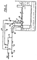
- the relatively low-power pilot burner of the invention identified as a whole 1, essentially comprises a premix chamber 2 supplied with air and combustible gas by separate inlets respectively 3 and 4, advantageously opening into this chamber 2 substantially radially at 13 and 14.
- the chamber 2 which has the general shape of an elongated cylindrical box with substantially circular section is closed on its front face by a metal grid 5 for stabilization and d hanging of flames.
- This grid which is therefore relatively sensitive to thermal stresses (compared to ceramic plates) may, as known per se, have orifices of suitable diameter and distribution to ensure good adhesion and good stabilization of the flames at the entrance to the chamber. burner 6.
- the air and fuel gas inlets 3 and 4 open into the chamber 2 towards the end opposite the grid 5.
- the combustion chamber 6 constitutes the combustion chamber of the main burner, (marked 10).
- the premix chamber 2 On its rear face, the premix chamber 2 is closed by a wall 8 on which is mounted, in leaktight manner, in order to resist the internal pressure of the premix chamber, a means of visual control 9 of the flame.
- This control means can consist of a glass plate.
- FIG. 1 it will be noted that the front and rear sides of the burner have been identified by the letters AV and AR respectively, referring to the circulation of air and combustible gas, then of the gas mixture. in the burner, as shown by the arrows.
- the ignition of the burner is ensured by an electrode 11 supplied with high voltage suitable as shown in diagram 12 and suitably isolated, the ignition being effected by sparks or electric arc between the tip 13 'of the electrode d ignition and the adjacent wall of the grid 5 suitably grounded of the box forming the distribution chamber 2.
- the electric power supply cable 9 of the electrode 11 crosses, in a pressure-tight manner in the chamber in question, at 15, the wall of this chamber. Sealing can in particular be ensured by means of a cable gland.
- the air inlet 3 is provided with a passage 16 of relatively small cross section relative to that of the duct 3 , this orifice being formed in a part 17 of the diaphragm type, while on the complementary supply 4 of combustible gas, there is provided a member 18 with calibrated orifice 19, of the type injector or the like.
- the injector 18 is disposed at the opening 14 of the inlet 4 opening into the premix chamber 2.
- the gas flow rate is automatically adjusted to the value required by the calibrated injector regardless of the pressure variations of the gas supply (within a current range).
- the pilot pilot burner 1 is connected to the higher power burner, marked 10, by means of a tube 24 plunging into the bath 7 to be heated and having a slightly diameter more important than that of the chamber 2.
- This tube 24 can consist of a substantially vertical projection projecting from the wall of the combustion chamber 6.
- a joint or support plane 25 situated above the level 7 ′ of the bath 7 allows the pilot burner to be correctly positioned with respect to the main burner 6, so that the pilot opens substantially perpendicularly into the combustion chamber 6 of the main burner, extending only very slightly therein in order to do not disturb the operating conditions of said main burner.
- Seals 26 can seal between the base of the tube 24 and the opposite part of the pilot premix chamber.
- the immersion depth of the main burner 10 is, in practice, currently not limited.
- such an ionization electrode 27 is, when provided, advantageously mounted with the ignition electrode 11, towards the central part of the flame stabilization grid 5, substantially parallel to the direction d flow of the fuel mixture from the premix chamber 2 to the combustion chamber 6.
- the pilot burner 1 is supplied with combustible gas by a pipe 30 connected to the general distribution channel 34, and with air by a pipe 31, the air and combustible gas inlets 3 and 4 in FIG. 1 constituting the through ends of the pipes 30 and 31 at the level of the premix chamber of the burner.
- the lines 30 and 31 show the valves 23 and 22.
- the pipe 31 for supplying air to the pilot is in fact an air pipe coming from the pipe for supplying air to the main burner.
- the “total" air necessary to ensure good operating conditions for the pilot burner 1 and the main burner 10 immersed in the heating bath 7, is supplied by a fan or compressor 32 which supplies not only the pipe 31, but also driving 33.
- the main burner 10 is supplied with air by this pipe 33 and with combustible gas by a pipe 35 also connected to the general distribution channel 34, the premix being then delivered to the supply pipe 36 to the burner 10.
- the main burner 10 is ignited, as known per se, by means of the pilot burner 1.
- the pilot burner 1 is supplied with an air / combustible gas ratio lower than the stoichiometric dosage.
- the main burner 10 is supplied with premix with a slight excess of air.
- the air / fuel gas dosage of the pilot burner is perfected by an additional supply of air at the level of the grate shown diagrammatically in 5 opening into the combustion chamber 6, thus achieving the stoichiometric dosage of the fuel mixture of the burner- pilot 1.
- the excess air present in the feed premix of the main burner 10 and which is used by the pilot burner 1 makes it possible to find substantially stoichiometric conditions at the level of the main burner 10.
Landscapes
- Engineering & Computer Science (AREA)
- Chemical & Material Sciences (AREA)
- Combustion & Propulsion (AREA)
- Mechanical Engineering (AREA)
- General Engineering & Computer Science (AREA)
- Gas Burners (AREA)
- Pre-Mixing And Non-Premixing Gas Burner (AREA)
Claims (6)
Priority Applications (1)
| Application Number | Priority Date | Filing Date | Title |
|---|---|---|---|
| AT87402425T ATE56806T1 (de) | 1986-11-07 | 1987-10-27 | Vormischgasbrenner mit druckluftfuehrung. |
Applications Claiming Priority (2)
| Application Number | Priority Date | Filing Date | Title |
|---|---|---|---|
| FR8615556A FR2606490B1 (fr) | 1986-11-07 | 1986-11-07 | Bruleur a gaz du type a air souffle et a premelange |
| FR8615556 | 1986-11-07 |
Publications (3)
| Publication Number | Publication Date |
|---|---|
| EP0269487A1 EP0269487A1 (de) | 1988-06-01 |
| EP0269487B1 EP0269487B1 (de) | 1990-09-19 |
| EP0269487B2 true EP0269487B2 (de) | 1993-08-11 |
Family
ID=9340639
Family Applications (1)
| Application Number | Title | Priority Date | Filing Date |
|---|---|---|---|
| EP87402425A Expired - Lifetime EP0269487B2 (de) | 1986-11-07 | 1987-10-27 | Vormischgasbrenner mit Druckluftführung |
Country Status (10)
| Country | Link |
|---|---|
| US (1) | US4875850A (de) |
| EP (1) | EP0269487B2 (de) |
| JP (1) | JPS6488015A (de) |
| KR (1) | KR950013963B1 (de) |
| AT (1) | ATE56806T1 (de) |
| CA (1) | CA1303476C (de) |
| DE (1) | DE3765092D1 (de) |
| ES (1) | ES2017742T5 (de) |
| FR (1) | FR2606490B1 (de) |
| GR (1) | GR3000846T3 (de) |
Families Citing this family (10)
| Publication number | Priority date | Publication date | Assignee | Title |
|---|---|---|---|---|
| US5235804A (en) * | 1991-05-15 | 1993-08-17 | United Technologies Corporation | Method and system for combusting hydrocarbon fuels with low pollutant emissions by controllably extracting heat from the catalytic oxidation stage |
| US5318436A (en) * | 1991-11-14 | 1994-06-07 | United Technologies Corporation | Low NOx combustion piloted by low NOx pilots |
| GB2270750B (en) * | 1992-09-11 | 1996-08-14 | Stoves Ltd | Improvements in and relating to gas-fired cooking appliances |
| GB2304886B (en) * | 1995-08-31 | 2000-03-15 | Butler Tech Ltd | An apparatus and a method for heating a material |
| GB9812984D0 (en) * | 1998-06-16 | 1998-08-12 | Graveson Energy Management Ltd | Gasification reactor apparatus |
| GB9812975D0 (en) | 1998-06-16 | 1998-08-12 | Graveson Energy Management Ltd | Burner |
| US7340893B1 (en) * | 2004-05-14 | 2008-03-11 | Rowan James A | Steam generator system |
| US10677455B2 (en) | 2015-06-24 | 2020-06-09 | Khalifa University of Science and Technology | Electrostatically manipulated flames for compact heat generation |
| CN109059003A (zh) * | 2018-06-01 | 2018-12-21 | 柳州东侯生物能源科技有限公司 | 裂解气化炉 |
| KR101964989B1 (ko) * | 2018-09-12 | 2019-04-02 | 국방과학연구소 | 연소기 점화용 토치 점화기 |
Family Cites Families (17)
| Publication number | Priority date | Publication date | Assignee | Title |
|---|---|---|---|---|
| DE1008855B (de) * | 1939-12-13 | 1957-05-23 | Neubecker Fa C A | Zuendvorrichtung bei Gasfeuerungen mit UEberdruck im Brennraum |
| FR1057371A (fr) * | 1952-05-26 | 1954-03-08 | Heurtey & Cie | Dispositif de chauffage |
| US3228451A (en) * | 1957-06-25 | 1966-01-11 | Urquhart S 1926 Ltd | Method of burning fuels |
| US3192920A (en) * | 1963-09-03 | 1965-07-06 | Submerged Comb Inc | Combustion apparatus and control system therefor |
| US3730668A (en) * | 1971-03-03 | 1973-05-01 | Tokyo Gas Co Ltd | Combustion method of gas burners for suppressing the formation of nitrogen oxides and burner apparatus for practicing said method |
| US3770369A (en) * | 1971-03-31 | 1973-11-06 | Mitsui Shipbuilding Eng | Method of burning liquid fuel in fluid bed apparatus |
| US3890084A (en) * | 1973-09-26 | 1975-06-17 | Coen Co | Method for reducing burner exhaust emissions |
| US3957421A (en) * | 1974-09-03 | 1976-05-18 | Raytheon Company | Heat injector gas burner |
| JPS5812481B2 (ja) * | 1976-03-01 | 1983-03-08 | 株式会社日立製作所 | バ−ナ |
| US4224019A (en) * | 1978-02-27 | 1980-09-23 | Westinghouse Electric Corp. | Power burner for compact furnace |
| US4236464A (en) * | 1978-03-06 | 1980-12-02 | Aerojet-General Corporation | Incineration of noxious materials |
| JPS5691108A (en) * | 1979-12-21 | 1981-07-23 | Babcock Hitachi Kk | Combustion method capable of reducing nox and uncombusted substance |
| NL8005717A (nl) * | 1980-10-16 | 1982-05-17 | Nefit Nv | Verwarmingsketel alsmede een werkwijze voor het regelen van de verbranding in een dergelijke ketel. |
| FR2510731A1 (fr) * | 1981-08-03 | 1983-02-04 | Hublard Marcel | Appareil de chauffage, notamment bruleur a gaz atmospherique pour chaudieres |
| DE3230853A1 (de) * | 1982-08-19 | 1984-02-23 | Stünkel, Klaus-Erich, 3000 Hannover | Geschlossene vorbaubrennkammer mit druckluft-gasbrenner fuer erdoel-erdgas erwaermungs-und erdoel erwaermungs- und trennungsvorrichtungen |
| FR2547394B1 (fr) * | 1983-06-08 | 1987-07-17 | Gaz De France | Bruleur a gaz du type a premelange et a controle de flamme et utilisation de ce bruleur en particulier pour installation a tube immerge |
| FR2589555B1 (fr) * | 1985-11-06 | 1989-11-10 | Gaz De France | Bruleur a gaz a air souffle |
-
1986
- 1986-11-07 FR FR8615556A patent/FR2606490B1/fr not_active Expired - Lifetime
-
1987
- 1987-10-27 DE DE8787402425T patent/DE3765092D1/de not_active Expired - Lifetime
- 1987-10-27 EP EP87402425A patent/EP0269487B2/de not_active Expired - Lifetime
- 1987-10-27 ES ES87402425T patent/ES2017742T5/es not_active Expired - Lifetime
- 1987-10-27 AT AT87402425T patent/ATE56806T1/de not_active IP Right Cessation
- 1987-10-29 KR KR1019870012012A patent/KR950013963B1/ko not_active Expired - Fee Related
- 1987-11-02 US US07/115,728 patent/US4875850A/en not_active Expired - Lifetime
- 1987-11-06 CA CA000551191A patent/CA1303476C/fr not_active Expired - Lifetime
- 1987-11-07 JP JP62281940A patent/JPS6488015A/ja active Pending
-
1990
- 1990-09-20 GR GR90400398T patent/GR3000846T3/el unknown
Also Published As
| Publication number | Publication date |
|---|---|
| CA1303476C (fr) | 1992-06-16 |
| FR2606490A1 (fr) | 1988-05-13 |
| KR950013963B1 (ko) | 1995-11-18 |
| US4875850A (en) | 1989-10-24 |
| KR880006505A (ko) | 1988-07-23 |
| JPS6488015A (en) | 1989-04-03 |
| ES2017742B3 (es) | 1991-03-01 |
| ATE56806T1 (de) | 1990-10-15 |
| EP0269487A1 (de) | 1988-06-01 |
| ES2017742T5 (es) | 1995-08-01 |
| EP0269487B1 (de) | 1990-09-19 |
| FR2606490B1 (fr) | 1990-07-13 |
| DE3765092D1 (de) | 1990-10-25 |
| GR3000846T3 (en) | 1991-11-15 |
Similar Documents
| Publication | Publication Date | Title |
|---|---|---|
| CA1278251C (fr) | Bruleur a gaz a air souffle | |
| US3649211A (en) | Air augmented duct burner | |
| US5431559A (en) | Oxygen-fuel burner with staged oxygen supply | |
| CA2478876C (fr) | Systeme d'injection air/carburant ayant des moyens de generation de plasmas froids | |
| EP0269487B1 (de) | Vormischgasbrenner mit Druckluftführung | |
| US2880792A (en) | Flame igniter | |
| EP0171788A1 (de) | Zündungs- und Erhaltungsbrenner für festen, fossilen und zerstäubten Brennstoff und Verbrennungskammer mit solchen Brennern | |
| FR2640357A1 (fr) | Bruleur a gaz empechant une combustion incomplete | |
| CN1272910A (zh) | 燃烧器 | |
| WO2005059440A1 (fr) | Procede de combustion etagee avec injection optimisee de l'oxydant primaire | |
| EP0270424A1 (de) | Zündvorrichtung für Hochgeschwindigkeitsbrenner mit kalter Düse und Brenner, der mit dieser Vorrichtung versehen ist | |
| FR2608258A1 (fr) | Dispositif de combustion pour un moteur a turbine a gaz | |
| EP1016828B1 (de) | Einspritzdüse für Brenner und entsprechendes Einspritzsystem | |
| EP0128809B1 (de) | Gasbrenner des Vormischtyps und mit Flammenüberwachung und Anwendung dieses Brenners insbesondere für Tauchrohranlage | |
| US3980422A (en) | Oil injection means for liquid fuel burner | |
| JP3096749B2 (ja) | バーナ | |
| EP0269488B1 (de) | Vormischgasbrenner mit Flammenüberwachung | |
| RU2169885C1 (ru) | Запальник | |
| KR100526121B1 (ko) | 복사관 버너의 착화장치 | |
| FR2570473A1 (fr) | Perfectionnements aux bruleurs a gaz a ecoulement parallele comportant une rosace et un moyeu d'accrochage de flamme concernant les bruleurs a gaz et l'alimentation independante en air central | |
| EP0190091B1 (de) | Gas-Stabbrenner mit mechanischer Luftzuführung | |
| EP0162761B1 (de) | Brenner mit Schaufeln und ausgeglichener Zweitluftzufuhr | |
| FR2641057A1 (en) | Combustion head for a gas burner, or combined gas-and-paraffin burner and burner equipped with such a head | |
| EP4184059A1 (de) | Brennstoffkessel mit einer vorrichtung zur verringerung des drucks für die zündung der flamme | |
| FR2564182A1 (fr) | Bruleur pour foyer comportant un convergent |
Legal Events
| Date | Code | Title | Description |
|---|---|---|---|
| PUAI | Public reference made under article 153(3) epc to a published international application that has entered the european phase |
Free format text: ORIGINAL CODE: 0009012 |
|
| AK | Designated contracting states |
Kind code of ref document: A1 Designated state(s): AT BE CH DE ES GB GR IT LI LU NL SE |
|
| 17P | Request for examination filed |
Effective date: 19881005 |
|
| 17Q | First examination report despatched |
Effective date: 19890202 |
|
| GRAA | (expected) grant |
Free format text: ORIGINAL CODE: 0009210 |
|
| AK | Designated contracting states |
Kind code of ref document: B1 Designated state(s): AT BE CH DE ES GB GR IT LI LU NL SE |
|
| REF | Corresponds to: |
Ref document number: 56806 Country of ref document: AT Date of ref document: 19901015 Kind code of ref document: T |
|
| ITF | It: translation for a ep patent filed | ||
| GBT | Gb: translation of ep patent filed (gb section 77(6)(a)/1977) | ||
| REF | Corresponds to: |
Ref document number: 3765092 Country of ref document: DE Date of ref document: 19901025 |
|
| REG | Reference to a national code |
Ref country code: GR Ref legal event code: FG4A Free format text: 3000846 |
|
| PLBI | Opposition filed |
Free format text: ORIGINAL CODE: 0009260 |
|
| PLBI | Opposition filed |
Free format text: ORIGINAL CODE: 0009260 |
|
| 26 | Opposition filed |
Opponent name: JOH. VAILLANT GMBH U. CO Effective date: 19910615 |
|
| 26 | Opposition filed |
Opponent name: STIEBEL ELTRON GMBH & CO.KG Effective date: 19910619 Opponent name: JOH. VAILLANT GMBH U. CO Effective date: 19910615 |
|
| NLR1 | Nl: opposition has been filed with the epo |
Opponent name: JOH. VAILLANT GMBH U. CO. |
|
| NLR1 | Nl: opposition has been filed with the epo |
Opponent name: STIEBEL ELTRON GMBH & CO.KG. |
|
| ITTA | It: last paid annual fee | ||
| PUAH | Patent maintained in amended form |
Free format text: ORIGINAL CODE: 0009272 |
|
| STAA | Information on the status of an ep patent application or granted ep patent |
Free format text: STATUS: PATENT MAINTAINED AS AMENDED |
|
| 27A | Patent maintained in amended form |
Effective date: 19930811 |
|
| AK | Designated contracting states |
Kind code of ref document: B2 Designated state(s): AT BE CH DE ES GB GR IT LI LU NL SE |
|
| REG | Reference to a national code |
Ref country code: CH Ref legal event code: AEN |
|
| ITF | It: translation for a ep patent filed | ||
| NLR2 | Nl: decision of opposition | ||
| NLR3 | Nl: receipt of modified translations in the netherlands language after an opposition procedure | ||
| PG25 | Lapsed in a contracting state [announced via postgrant information from national office to epo] |
Ref country code: GR Free format text: THE PATENT HAS BEEN ANNULLED BY A DECISION OF A NATIONAL AUTHORITY Effective date: 19931104 |
|
| EPTA | Lu: last paid annual fee | ||
| GBTA | Gb: translation of amended ep patent filed (gb section 77(6)(b)/1977) |
Effective date: 19931124 |
|
| REG | Reference to a national code |
Ref country code: GR Ref legal event code: FG4A Free format text: 3009602 |
|
| EAL | Se: european patent in force in sweden |
Ref document number: 87402425.0 |
|
| REG | Reference to a national code |
Ref country code: ES Ref legal event code: DC2A Kind code of ref document: T5 Effective date: 19950801 |
|
| REG | Reference to a national code |
Ref country code: GB Ref legal event code: IF02 |
|
| PGFP | Annual fee paid to national office [announced via postgrant information from national office to epo] |
Ref country code: AT Payment date: 20060926 Year of fee payment: 20 Ref country code: CH Payment date: 20060926 Year of fee payment: 20 Ref country code: GB Payment date: 20060926 Year of fee payment: 20 |
|
| PGFP | Annual fee paid to national office [announced via postgrant information from national office to epo] |
Ref country code: NL Payment date: 20060927 Year of fee payment: 20 Ref country code: LU Payment date: 20060927 Year of fee payment: 20 Ref country code: BE Payment date: 20060927 Year of fee payment: 20 |
|
| PGFP | Annual fee paid to national office [announced via postgrant information from national office to epo] |
Ref country code: DE Payment date: 20060928 Year of fee payment: 20 Ref country code: GR Payment date: 20060928 Year of fee payment: 20 |
|
| PGFP | Annual fee paid to national office [announced via postgrant information from national office to epo] |
Ref country code: SE Payment date: 20060929 Year of fee payment: 20 |
|
| PGFP | Annual fee paid to national office [announced via postgrant information from national office to epo] |
Ref country code: ES Payment date: 20061019 Year of fee payment: 20 |
|
| PGFP | Annual fee paid to national office [announced via postgrant information from national office to epo] |
Ref country code: IT Payment date: 20061031 Year of fee payment: 20 |
|
| REG | Reference to a national code |
Ref country code: GB Ref legal event code: PE20 |
|
| REG | Reference to a national code |
Ref country code: CH Ref legal event code: PL |
|
| BE20 | Be: patent expired |
Owner name: *GAZ DE FRANCE Effective date: 20071027 |
|
| NLV7 | Nl: ceased due to reaching the maximum lifetime of a patent |
Effective date: 20071027 |
|
| REG | Reference to a national code |
Ref country code: ES Ref legal event code: FD2A Effective date: 20071029 |
|
| PG25 | Lapsed in a contracting state [announced via postgrant information from national office to epo] |
Ref country code: NL Free format text: LAPSE BECAUSE OF EXPIRATION OF PROTECTION Effective date: 20071027 |
|
| PG25 | Lapsed in a contracting state [announced via postgrant information from national office to epo] |
Ref country code: ES Free format text: LAPSE BECAUSE OF EXPIRATION OF PROTECTION Effective date: 20071029 Ref country code: GB Free format text: LAPSE BECAUSE OF EXPIRATION OF PROTECTION Effective date: 20071026 |