EP0268535B1 - Drehbarer Führungsring für Geschosse jeden Kalibers - Google Patents
Drehbarer Führungsring für Geschosse jeden Kalibers Download PDFInfo
- Publication number
- EP0268535B1 EP0268535B1 EP87402608A EP87402608A EP0268535B1 EP 0268535 B1 EP0268535 B1 EP 0268535B1 EP 87402608 A EP87402608 A EP 87402608A EP 87402608 A EP87402608 A EP 87402608A EP 0268535 B1 EP0268535 B1 EP 0268535B1
- Authority
- EP
- European Patent Office
- Prior art keywords
- projectile
- belt
- opening
- obturator
- ring
- Prior art date
- Legal status (The legal status is an assumption and is not a legal conclusion. Google has not performed a legal analysis and makes no representation as to the accuracy of the status listed.)
- Expired - Lifetime
Links
Images

Classifications
-
- F—MECHANICAL ENGINEERING; LIGHTING; HEATING; WEAPONS; BLASTING
- F42—AMMUNITION; BLASTING
- F42B—EXPLOSIVE CHARGES, e.g. FOR BLASTING, FIREWORKS, AMMUNITION
- F42B14/00—Projectiles or missiles characterised by arrangements for guiding or sealing them inside barrels, or for lubricating or cleaning barrels
- F42B14/02—Driving bands; Rotating bands
Definitions
- the technical sector of the present invention is that of windbreaking belts equipping projectiles of any caliber fired using a rifled barrel tube.
- slip belt The concept of the slip belt is that which is used both in France and abroad to allow the firing of kinetic energy ammunition, of the arrow type, and this, from heavily striped tubes.
- the non-slip belts developed for currently known arrow munitions are made of plastic and are mounted on the projectile by hot deformation. After cooling, these belts rotate freely on the projectile with a residual play that is difficult to reproduce due to the passage of the material in permanent deformation since its mechanical properties are modified.
- patents US-A-4,187,783 and DE-A-2,331,158 In the American patent, a belt is provided for an arrow projectile on which a sealing layer is applied, capable of sliding one with respect to the other to reduce the rotation of the projectile.
- the tightness in the tube must be ensured at the level of the belt so as not to degrade the performance of the weapon system.
- Means annexed to the belt have been proposed to ensure this tightness, consisting of a bead linked to the belt by a complex structure.
- Patent FR-A 2 331 771 describes a tailed projectile provided with a sliding guide ring, rotatably mounted on the body of the projectile. It is above all a question of overcoming the great precision necessary for assembly by providing a ring in three parts, maintained until firing by a safety lock. This ring is mounted in a sliding cage or placed in its housing with a certain clearance. However, the production of the ring in three parts, made of sintered metal, does not prevent sealing between the projectile and the tube of the weapon.
- Patent FR-A 1 093 020 relates to means for reducing the rotation of a projectile by providing a slip belt mounted between two parts of a munition joined axially by screwing.
- reducing gyration requires taking into account a number of factors that are difficult to control. Indeed, the very design of the ammunition is different and requires delicate machining in order to adapt this belt.
- the belt is mounted in a recess and the walls of the latter are graphitized or coated with an anti-friction material to facilitate sliding.
- a sliding ring is provided between the belt and the projectile, the belt then being a free ring.
- the belt is made of sintered metal and has no teeth on its internal surface.
- the purpose of the present invention is therefore to avoid the drawbacks mentioned above by proposing a slip belt transmitting only a small rotation to the projectile by increasing the radial clearance between the belt and the projectile during the launching phase of the latter. ci, while ensuring the tightness in the barrel of the weapon.
- the invention therefore relates to a device constituting a slip belt for projectile fired in a striped tube, consisting of a ring disposed in a housing formed on the projectile, a grain before placed against the anterior edge of the housing, a plastic body belt placed in the housing and an axial locking means of the body in the housing, characterized in that this body has circular teeth in contact with the ring.
- the outside diameter of the belt body can be substantially greater than the diameter of the stripes in the tube.
- the belt body may be provided with a rear skirt which is not adherent to the projectile, comprising a groove for crimping the shell of the ammunition.
- the axial locking means may consist of radial pins fixed on the projectile, a grain being placed between the rear face of the body and the pins.
- the locking means can be constituted by a circular flange of the projectile.
- the belt body can be made up of two identical sectors joined by assembly screws.
- the front grain can be in the form of a disc.
- the front grain can be in the form of a disc provided with a frustoconical inner lip.
- the diameter of the front grain may be less than that of the projectile, so as to provide a free space between the front of the belt body and the front edge of the housing.
- the total surface of the tooth contacts can be equal to or less than 25% of the surface of the ring.
- An advantage of the present invention lies in the fact that the radial clearance between the belt and the projectile is constant and reproducible from one munition to another, which does not affect the performance of the weapon system.
- Another advantage lies in the fact that the mounting operations involve only the elastic deformations of the material constituting the belt body.
- Another advantage is that this game is kept in a temperature range of - 40 ° C to + 63 ° C.
- this belt can be applied to any type of ammunition whether it is small, medium or large caliber.
- FIG. 1 Partially diagrammatically shown in FIG. 1 is an arrow projectile conventionally constituted by a launch shoe 1 and an arrow not shown.
- This projectile is placed in the barrel of the weapon at the level of the chamber 3 and the forcing cone 4.
- the projectile comprises a housing 5 on which is placed a ring 6 and at the front a grain 7a having the form a disc with a frustoconical inner lip.
- a belt body 8 provided with teeth 9 is placed in contact with the ring 6 and bears on the front grain 7a.
- These teeth 9 are, in the figures, in the form of a V, but they could also be in the form of a U. They can be produced in the form of a single helical groove, or alternatively in the form of parallel grooves.
- the total contact surface of the teeth is less than or equal to 25% of the surface of the ring 8.
- the belt 8 is extended rearwards by a skirt 10 without contact with the projectile 1.
- This skirt carries a circular groove 11 in which the sleeve 12 is crimped by constriction as shown by arrow A.
- Pawns 13 fixed radially in the projectile shoe limit rearward movement of the belt.
- a rear grain 7b can be placed between the rear face of the body 8 and the pins 13 so as to facilitate the sliding of the belt.
- Radial holes 14 made in the groove 11 allow the passage of the pins 13.
- the belt can be retained using six pins arranged regularly over a diameter of the projectile. In the figure, it can be seen that the external diameter (a) of the belt is slightly greater than the diameter (b) of the stripes 15 on the tube, that is to say from 1 to 2 mm.
- the structure described above makes it possible to ensure mechanical mounting of the various elements, that is to say without deformation.
- the front grain 7a is first placed against the front face 15 of the housing 5, then the ring 6 is threaded onto the projectile and finally the belt body 8 is placed around the ring 6 and against the grain 7a with a very slight Tightening.
- the rear grain 7b is placed and the pins 13 are then fixed, then the sleeve.
- a free space 7c can be provided between the grain 7a and the ring 6 and / or 7d between the grain 7b and the pins 13.
- FIG. 2 an alternative embodiment different from the previous embodiment is shown by the depth p 2 of the housing 5 which is greater than the value p i shown in FIG. 1.
- the thickness of the belt 8 is greater and a space 16 is provided between the front of this belt and the projectile.
- the displacement of the contact zone of the belt 8 towards the axis of the projectile thus makes it possible, at equal pressure, to reduce the driving torque of the projectile in rotation by reducing the mean radius of the front grain.
- the mounting of the front grain 7a, the ring 6 and the belt 8 is strictly identical to that of the previous mode. Note that the grain 7a is in the form of a disc.
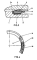
- FIG 3 there is shown an embodiment of the belt according to the invention in which the pins are replaced by a circular flange 17 of the projectile defining a housing of the belt body.
- the skirt 10 has no radial perforation and the sleeve 12 is crimped in the groove 11.
- This structure requires mounting of the grain 7a, of the ring 6 and of the belt by elastic and not permanent deformation on the projectile. In this configuration, no rear grain is placed between the body and the collar.
- the belt body 8 is very thick on the order of 20 mm, to allow good scratching and to avoid too much tightening at the level of the projectile. Note that the thickness commonly used in this technical field is around 8 mm.
- the belt 8 is made of conventional plastic material of the polyamide type and has a cone which matches the forcing cone of the tube.
- the front grains 7a and rear 7b can be made of material of the polypropylene or low density polyethylene type, the material constituting the front grain preferably being of a lower Shore hardness than that of the rear grain.
- the front grain 7a is made of a very flexible material with a Shore hardness of the order of 10 to 20 and a density of the order of 50 Kf / m 3 to ensure a limitation of the projectile rotation drive.
- the ring 6 made of plastic of the polypropylene type on the one hand, participates in the locking of the elements of the shoe applied to the arrow, constituting the projectile, and on the other hand, limits the driving in rotation of the projectile. Finally, the stop pins 13 (two per shoe element) or the flange 17 retain the belt when taking scratches and allow the locking of the projectile in translation during handling.
- the speed of rotation transmitted to the projectile is approximately 70 to 80 revolutions / s whereas with a conventional belt the speed transmitted is approximately 560 revolutions / s.
- an assembly mode of the belt body 8 may include a number of sectors and in particular two half-shells 18 and 19 assembled by two screws 20 fixed in their thickness. This embodiment allows the belt to be mounted on the projectile described in Figure 3 without deformation.
- the housing 5 is formed directly on the body of the projectile.
Landscapes
- Engineering & Computer Science (AREA)
- General Engineering & Computer Science (AREA)
- Belt Conveyors (AREA)
- Lubricants (AREA)
- Compositions Of Macromolecular Compounds (AREA)
- Toys (AREA)
- Aiming, Guidance, Guns With A Light Source, Armor, Camouflage, And Targets (AREA)
- Measurement Of Force In General (AREA)
- Fishing Rods (AREA)
- Grinding And Polishing Of Tertiary Curved Surfaces And Surfaces With Complex Shapes (AREA)
- Valve-Gear Or Valve Arrangements (AREA)
Claims (10)
Priority Applications (1)
| Application Number | Priority Date | Filing Date | Title |
|---|---|---|---|
| AT87402608T ATE54365T1 (de) | 1986-11-19 | 1987-11-19 | Drehbarer fuehrungsring fuer geschosse jeden kalibers. |
Applications Claiming Priority (2)
| Application Number | Priority Date | Filing Date | Title |
|---|---|---|---|
| FR8616066 | 1986-11-19 | ||
| FR8616066A FR2606869B1 (fr) | 1986-11-19 | 1986-11-19 | Ceinture derapante pour projectile de tout calibre |
Publications (2)
| Publication Number | Publication Date |
|---|---|
| EP0268535A1 EP0268535A1 (de) | 1988-05-25 |
| EP0268535B1 true EP0268535B1 (de) | 1990-07-04 |
Family
ID=9340962
Family Applications (1)
| Application Number | Title | Priority Date | Filing Date |
|---|---|---|---|
| EP87402608A Expired - Lifetime EP0268535B1 (de) | 1986-11-19 | 1987-11-19 | Drehbarer Führungsring für Geschosse jeden Kalibers |
Country Status (5)
| Country | Link |
|---|---|
| EP (1) | EP0268535B1 (de) |
| AT (1) | ATE54365T1 (de) |
| DE (1) | DE3763578D1 (de) |
| ES (1) | ES2016379B3 (de) |
| FR (1) | FR2606869B1 (de) |
Families Citing this family (7)
| Publication number | Priority date | Publication date | Assignee | Title |
|---|---|---|---|---|
| FR2665761B1 (fr) * | 1990-08-13 | 1994-09-16 | Giat Ind Sa | Ceinture d'etancheite pour projectile fleche. |
| FR2670880B1 (fr) * | 1990-12-19 | 1993-03-26 | Giat Ind Sa | Ceinture derapante pour projectile de tout calibre et son procede de realisation. |
| FR2721701B1 (fr) * | 1994-06-28 | 1996-08-14 | Giat Ind Sa | Empennage pour projectile, notamment pour projectile sous-calibré supersonique. |
| FR2732456B1 (fr) * | 1995-04-03 | 1997-05-16 | Giat Ind Sa | Amorces de rupture de ceinture pour projectile fleche |
| FR2768809B1 (fr) | 1997-09-24 | 1999-10-15 | Giat Ind Sa | Projectile d'artillerie de campagne de gros calibre a longue portee |
| FR2820495A1 (fr) | 2001-02-02 | 2002-08-09 | Anthena Soc | Projectile pour munitions a portee reduite |
| FR2882429B1 (fr) | 2005-02-21 | 2007-03-30 | Giat Ind Sa | Ceinture d'etancheite pour projectile d'artillerie |
Family Cites Families (7)
| Publication number | Priority date | Publication date | Assignee | Title |
|---|---|---|---|---|
| US2996992A (en) * | 1944-09-26 | 1961-08-22 | Charles L Critchfield | Projectile |
| NL183186B (nl) * | 1952-12-19 | Chinoin Gyogyszer Es Vegyeszet | Werkwijze voor de bereiding van aminozuur-derivaten en van farmaceutische voortbrengsels die ze bevatten, alsmede aldus verkregen farmaceutische voorwerpen. | |
| DE1083708B (de) * | 1958-11-05 | 1960-06-15 | Ludwig Bucklisch | Geschoss mit Fuehrungsring |
| US3834314A (en) * | 1972-12-29 | 1974-09-10 | Aai Corp | Puller sabot ammunition with slip seal |
| DE2551389A1 (de) * | 1975-11-15 | 1977-05-26 | Rheinmetall Gmbh | Fluegelstabilisiertes geschoss |
| US4242961A (en) * | 1978-10-23 | 1981-01-06 | Martin Marietta Corporation | Chevron grooved decoupling obturator |
| DE3510913A1 (de) * | 1985-03-26 | 1986-10-09 | Diehl GmbH & Co, 8500 Nürnberg | Projektil |
-
1986
- 1986-11-19 FR FR8616066A patent/FR2606869B1/fr not_active Expired - Fee Related
-
1987
- 1987-11-19 ES ES87402608T patent/ES2016379B3/es not_active Expired - Lifetime
- 1987-11-19 AT AT87402608T patent/ATE54365T1/de not_active IP Right Cessation
- 1987-11-19 EP EP87402608A patent/EP0268535B1/de not_active Expired - Lifetime
- 1987-11-19 DE DE8787402608T patent/DE3763578D1/de not_active Expired - Lifetime
Also Published As
| Publication number | Publication date |
|---|---|
| FR2606869A1 (fr) | 1988-05-20 |
| ATE54365T1 (de) | 1990-07-15 |
| EP0268535A1 (de) | 1988-05-25 |
| FR2606869B1 (fr) | 1990-10-05 |
| ES2016379B3 (es) | 1990-11-01 |
| DE3763578D1 (de) | 1990-08-09 |
Similar Documents
| Publication | Publication Date | Title |
|---|---|---|
| CH634142A5 (fr) | Mecanisme de lancement d'un projectile sous-calibre. | |
| EP0307307B1 (de) | Verbindungsring zwischen Geschoss und Geschosshülse | |
| EP0268535B1 (de) | Drehbarer Führungsring für Geschosse jeden Kalibers | |
| EP0491614B1 (de) | Drehbarer Führungsring für Geschosse jeden Kalibers und Verfahren zu seiner Herstellung | |
| EP0664877B1 (de) | Treibkäfig für unterkalibergeschosse mit kontrollierter trennung der teile | |
| WO1994021981A1 (fr) | Dispositif d'etancheite aux gaz de propulsion pour munitions d'artillerie | |
| EP2578987B1 (de) | Drallstabilisiertes Geschoss | |
| EP0401114B1 (de) | Vorrichtung zum Halten eines Geschosses in bezug auf das Gehäuse einer teleskopartigen Munition | |
| EP1693646B1 (de) | Führungsband für Artilleriegeschoss | |
| FR2774162A1 (fr) | Projectile a guide conique polygonal pour arme a feu a canon raye, et munition comportant un tel projectile | |
| EP0417012B1 (de) | Verbindungsvorrichtung für einen Treibspiegel eines Unterkalibergeschosses | |
| WO2021044065A1 (fr) | Obus anti-aérien pour munition télescopée à double déverrouillage | |
| EP0196262A2 (de) | Schrotpatronenpfropfen für Flinten oder andere Waffen sowie mit einem solchen Pfropfen versehene Patrone | |
| WO1991002211A1 (fr) | Perfectionnements apportes aux munitions destinees a etre tirees par une arme a canon lisse | |
| FR2597590A1 (fr) | Sabot de lancement pour projectiles sous-calibres | |
| FR2644881A1 (fr) | Dispositif de liaison entre un premier et deuxieme troncon d'un projectile gyrostabilise | |
| FR2507765A1 (fr) | Procede et dispositif de tir d'une munition fleche a l'aide d'un tube raye | |
| EP0530287B1 (de) | Tandemabschusssystem mit einer zentralen dichtanordnung | |
| FR2502766A1 (fr) | Canon d'arme a feu a chambre allongee | |
| FR2612621A1 (fr) | Ceinture derapante a spires pour projectiles de tout calibre | |
| CA2176029C (fr) | Balle de chasse a double penetration et a portee reduite | |
| EP0382657A1 (de) | Patrone für Gewehre oder andere Feuerwaffen | |
| FR3013114A1 (fr) | Dispositif de propulsion pour une munition utilisable avec un lanceur | |
| FR3018908A1 (fr) | Projectile gyrostabilise | |
| FR2848658A1 (fr) | Obus d'artillerie a grande portee |
Legal Events
| Date | Code | Title | Description |
|---|---|---|---|
| PUAI | Public reference made under article 153(3) epc to a published international application that has entered the european phase |
Free format text: ORIGINAL CODE: 0009012 |
|
| 17P | Request for examination filed |
Effective date: 19871204 |
|
| AK | Designated contracting states |
Kind code of ref document: A1 Designated state(s): AT BE DE ES GB IT NL |
|
| RAP1 | Party data changed (applicant data changed or rights of an application transferred) |
Owner name: ETAT-FRANCAIS REPRESENTE PAR LE DELEGUE GENERAL PO |
|
| 17Q | First examination report despatched |
Effective date: 19890203 |
|
| GRAA | (expected) grant |
Free format text: ORIGINAL CODE: 0009210 |
|
| AK | Designated contracting states |
Kind code of ref document: B1 Designated state(s): AT BE DE ES GB IT NL |
|
| REF | Corresponds to: |
Ref document number: 54365 Country of ref document: AT Date of ref document: 19900715 Kind code of ref document: T |
|
| ITF | It: translation for a ep patent filed |
Owner name: BARZANO' E ZANARDO MILANO S.P.A. |
|
| REF | Corresponds to: |
Ref document number: 3763578 Country of ref document: DE Date of ref document: 19900809 |
|
| GBT | Gb: translation of ep patent filed (gb section 77(6)(a)/1977) | ||
| PLBE | No opposition filed within time limit |
Free format text: ORIGINAL CODE: 0009261 |
|
| STAA | Information on the status of an ep patent application or granted ep patent |
Free format text: STATUS: NO OPPOSITION FILED WITHIN TIME LIMIT |
|
| 26N | No opposition filed | ||
| ITPR | It: changes in ownership of a european patent |
Owner name: CESSIONE;GIAT INDUSTRIES |
|
| ITTA | It: last paid annual fee | ||
| NLS | Nl: assignments of ep-patents |
Owner name: GIAT INDUSTRIES (SOCIETE ANONYME) TE VERSAILLES, F |
|
| REG | Reference to a national code |
Ref country code: GB Ref legal event code: 732 |
|
| PGFP | Annual fee paid to national office [announced via postgrant information from national office to epo] |
Ref country code: ES Payment date: 19951020 Year of fee payment: 9 |
|
| PGFP | Annual fee paid to national office [announced via postgrant information from national office to epo] |
Ref country code: NL Payment date: 19951130 Year of fee payment: 9 |
|
| PG25 | Lapsed in a contracting state [announced via postgrant information from national office to epo] |
Ref country code: ES Free format text: LAPSE BECAUSE OF NON-PAYMENT OF DUE FEES Effective date: 19961120 |
|
| PG25 | Lapsed in a contracting state [announced via postgrant information from national office to epo] |
Ref country code: NL Effective date: 19970601 |
|
| NLV4 | Nl: lapsed or anulled due to non-payment of the annual fee |
Effective date: 19970601 |
|
| PGFP | Annual fee paid to national office [announced via postgrant information from national office to epo] |
Ref country code: GB Payment date: 19991029 Year of fee payment: 13 |
|
| PGFP | Annual fee paid to national office [announced via postgrant information from national office to epo] |
Ref country code: DE Payment date: 19991104 Year of fee payment: 13 |
|
| PGFP | Annual fee paid to national office [announced via postgrant information from national office to epo] |
Ref country code: BE Payment date: 19991115 Year of fee payment: 13 |
|
| PG25 | Lapsed in a contracting state [announced via postgrant information from national office to epo] |
Ref country code: GB Free format text: LAPSE BECAUSE OF NON-PAYMENT OF DUE FEES Effective date: 20001119 |
|
| PG25 | Lapsed in a contracting state [announced via postgrant information from national office to epo] |
Ref country code: BE Free format text: LAPSE BECAUSE OF NON-PAYMENT OF DUE FEES Effective date: 20001130 |
|
| BERE | Be: lapsed |
Owner name: S.A. GIAT INDUSTRIES Effective date: 20001130 |
|
| GBPC | Gb: european patent ceased through non-payment of renewal fee |
Effective date: 20001119 |
|
| PG25 | Lapsed in a contracting state [announced via postgrant information from national office to epo] |
Ref country code: DE Free format text: LAPSE BECAUSE OF NON-PAYMENT OF DUE FEES Effective date: 20010801 |
|
| REG | Reference to a national code |
Ref country code: ES Ref legal event code: FD2A Effective date: 19971213 |
|
| PGFP | Annual fee paid to national office [announced via postgrant information from national office to epo] |
Ref country code: AT Payment date: 20041021 Year of fee payment: 18 |
|
| PG25 | Lapsed in a contracting state [announced via postgrant information from national office to epo] |
Ref country code: IT Free format text: LAPSE BECAUSE OF NON-PAYMENT OF DUE FEES;WARNING: LAPSES OF ITALIAN PATENTS WITH EFFECTIVE DATE BEFORE 2007 MAY HAVE OCCURRED AT ANY TIME BEFORE 2007. THE CORRECT EFFECTIVE DATE MAY BE DIFFERENT FROM THE ONE RECORDED. Effective date: 20051119 Ref country code: AT Free format text: LAPSE BECAUSE OF NON-PAYMENT OF DUE FEES Effective date: 20051119 |