EP0268408A2 - Arrangements de filtrage à réponse impulsionnelle finie à deux dimensions - Google Patents
Arrangements de filtrage à réponse impulsionnelle finie à deux dimensions Download PDFInfo
- Publication number
- EP0268408A2 EP0268408A2 EP87309812A EP87309812A EP0268408A2 EP 0268408 A2 EP0268408 A2 EP 0268408A2 EP 87309812 A EP87309812 A EP 87309812A EP 87309812 A EP87309812 A EP 87309812A EP 0268408 A2 EP0268408 A2 EP 0268408A2
- Authority
- EP
- European Patent Office
- Prior art keywords
- words
- filter
- store
- compression
- filter arrangement
- Prior art date
- Legal status (The legal status is an assumption and is not a legal conclusion. Google has not performed a legal analysis and makes no representation as to the accuracy of the status listed.)
- Granted
Links
Images


Classifications
-
- H—ELECTRICITY
- H03—ELECTRONIC CIRCUITRY
- H03H—IMPEDANCE NETWORKS, e.g. RESONANT CIRCUITS; RESONATORS
- H03H17/00—Networks using digital techniques
- H03H17/02—Frequency selective networks
- H03H17/0202—Two or more dimensional filters; Filters for complex signals
Definitions
- This invention relates to two-dimensional finite impulse response filter arrangements for filtering a signal that represents an image and comprises a sequence of digital words.
- an image can be characterised by a two-dimensional parameter known as spatial frequency, which is proportional to the reciprocal of the angle subtended to the eye of the viewer by the visual spectral components of the image.
- spatial frequency a two-dimensional parameter known as spatial frequency
- the concept of spatial frequency can more readily be appreciated by considering an image in the form of a series of uniformly spaced straight lines. For a fixed position of the viewer with respect to such an image, the image has a single spatial frequency which is inversely proportional to the apparent spacing of the lines.
- the spatial frequency is horizontal if the lines are vertical and spaced horizontally, vertical if the lines are horizontal and spaced vertically, and diagonal in other cases.
- the scaling theorem in Fourier analysis states that if an image signal is compressed in the spatial domain, that is if the spatial frequency of the image is increased, then the Fourier transform of the signal increases in the frequency domain (that is, the frequency (in Hz) of the signal increases); and vice versa.
- the image signal discussed above is a sampled signal, and Nyquist's Rule concerning the sampling of signals states that, in order not to lose information contained in a signal, the signal must be sampled at a frequency (fs) that is equal to at least twice the highest frequency of the signal, or twice the banwidth (fB) of the signal.
- fs frequency
- fB banwidth
- This criterion is complied with when the digital input signal is formed initially by horizontally sampling an analogue signal.
- the frequency spectrum (Fourier transform) of the sampled signal in the frequency domain is shown by the solid lines in Figure 1 of the accompanying drawings, which is a graph of amplitude v. frequency (Hz).
- the frequency spectrum comprises a baseband component 10 (up to fB).
- the baseband is reflected symetrically around the sampling frequency fs and its harmonics 2fs, 3fs etc. to produce higher frequency components 12.
- Nyquist's Rule is complied with (so that fs/2 is greater than fB) and provided that the signal is band-limited (low-pass filtered) so as to have a cut-off frequency of about fs/2, the higher frequency components 12 will be suppressed.
- a filter can be positioned in advance of the compression means to filter out those parts of the two-dimensional input spectrum that otherwise would exceed the Nyquist limit frequency (fs/2) once compression has been carried out.
- the filter should have a flat pass band, infinite attenuation in the stop band and a transition band whose width approaches zero.
- 2D two-dimensional finite impulse response
- FIR finite impulse response
- the 2D-FIR filter is operative to calculate an output word or sample by multiplying a predetermined set (an array) of vertically and horizontally spaced words or samples of its input signal by respective weighting coefficients and summing the products of the multiplication operations.
- the necessary temporal delays to achieve the desired spatial relationship of the predetermined set of input words or samples can be achieved by delay elements positioned either in advance of or after respective multipliers used to carry out the multiplication operations. The delay elements can thus be considered to "tap" the image signal, in both directions. The response of the filter approaches more closely that of an ideal filter as the number of taps is increased.
- a compression means for example a digital video effects unit
- the extent of compression being selectable in, for example, an infinitely variable manner.
- the compression means is preceded by a 2D-FIR filter whose bandwidth is adjusted in accordance with the extent or degree of compression so as to avoid or at least reduce aliasing which otherwise would occur, in the event of compression, in the manner described above.
- the image may be compressed in either or both of the horizontal and vertical directions, possibly by different respective degrees; and that a 2D-FIR filter has both horizontal and vertical bandwidths which may be varied independently of one another by suitably choosing the values of the weighting coefficients.
- bandwidth and compression apply independently to the horizontal and vertical directions, respectively.
- the bandwidth of a system for handling two-dimensional (vertical/horizontal) sampled image signal can be represented in the spatial domain by a two-dimensional frequency response as represented in Figure 3 of the accompanying drawings.
- the horizontal axis represents a scale of horizontal spatial frequency in the positive and negative senses (H+ and H-) in units of cycles per picture (image) width;
- the vertical axis represents a scale of vertical spatial frequency in the positive and negative senses (V+ and V-) in units of cycles per picture (image) height;
- the rectangle 14 represents the two-dimensional bandwidth of the system;
- the dimensions 16 and 18 represent the vertical and horizontal bandwidths, respectively.
- the vertical and horizontal bandwidths can be controlled by varying the values of the weighting coefficients.
- a 2D-FIR filter arrangement for filtering a signal that represents an image and comprises a sequence of digital words spaced in time by an interval T, the filter arrangement comprising a 2D-FIR filter operative during each of a plurality of successive clock periods equal to T to effect filtration over a predetermined area of the image by processing a set of words of the image signal having a predetermined spatial relationship to produce therefrom an intermediate word; storage means for storing at least some of the intermediate words produced during the successive clock periods; and control means responsive to a signal indicating an extent to which the image is to be compressed to cause the FIR filter to adopt a bandwidth which is reduced, with respect to a value of the bandwidth for zero compression, by an extent related to the extent of compression, and to cause a plurality of the intermediate words, the size of which plurality is related to the extent of compression, to be combined so as to produce output words representative of filtration over a larger area of the image which is a multiple
- Such a 2D-FIR filter arrangement takes advantage of the fact that, when an image signal is to be subjected to substantial compression, some of the samples or words thereof are not needed. Accordingly, the filter arrangement produces output words which each comprise a combination of intermediate words generated during respective clock periods. Thus, each output word is representative of filtration over an area of the image which is a multiple of the predetermined area corresponding to the set of words processed during each clock period. In other words, each output word effectively is equivalent to a word which would have been obtained if the number of taps of the 2D-FIR filter had been increased by the same multiple. Thus, the filter arrangement operates as if the number of taps were increased as the extent of the compression (the compression factor) is increased.
- a filter arrangement comprising a filter having a number of taps sufficient for use in the case of zero or low compression can function effectively over a wide range of compression factors where, with a conventional filter, many more taps would be needed to provide a satisfactory response.
- Such a 2D-FIR filter arrangement further comprises a plurality of multipliers, and a coefficient store containing a plurality of different sets of weighting coefficients corresponding respectively to a plurality of different filter bandwidths.
- the control means is then operative to select from the coefficient store, for supply to the multipliers, a set of weighting coefficients that will cause the filter arrangement to have a bandwidth appropriately related to the extent of the compression.
- the number of bits to be stored in the store can become excessively large. This is because the number of bits is determined by the product of the number of taps which the filter arrangement is to have in each of the two dimensions; the maximum filter size (which for an image signal is the product of the number of samples in the horizontal direction and the number of samples in the vertical direction in the image); the number of positions in the array of interpolated positions to be used; and the number of bits used to represent each weighting coefficient. Clearly this can result in an unacceptably large number of bits to be stored, or in the quality of the filter arrangement being reduced so as to bring the number of bits to be stored to an acceptable number.
- variable separable filter An alternative which might be considered is the use of a variable separable filter.
- the bandwidth can be well controlled in the horizontal and vertical directions, but cannot be very well controlled in diagonal directions.
- Such a filter cannot therefore be used where digital video effects are to be created, because if the image is rotated, out-of-band components from diagonal directions will go into the horizontal and vertical directions and cause aliasing.
- two-dimensional finite impulse response filter arrangement for filtering a signal which represents an image and which comprises a sequence of digital words
- the filter arrangement comprising: a two-dimensional finite impulse response filter operative during each of a plurality of successive clock periods to effect filtration over a predetermined area of said image by multiplying each of a set of said digital words in a spatial array by a respective weighting coefficient in a corresponding set of weighting coefficients, and summing the resulting products to produce therefrom an output filtered digital word;
- said filter includes: a store storing weighting coefficient data defining a profile which when rotated about an axis generates a three-dimensional representation of the values of weighting coefficients corresponding to a required two-dimensional response characteristic of said filter; first calculaing means operative in response to each of said digital words to calculate the radius from said axis of the position of the corresponding said weighting coefficient in said representation, whereby the value of the respective weighting coefficient corresponding to each of the positions in said
- the capacity of the store can be reduced, in some instances by some orders of magnitude, compared with that required in the previously proposed 2D-FIR filter arrangement discussed above.
- the weighting coefficient data to be stored corresponds, in effect, to that for a one-dimensional filter array, instead of that for a two-dimensional filter array.
- the main additional requirement is for the first calculating means, but this need not involve any very substantial additional hardware.
- Figure 4 represents a two-dimensional digital image signal obtained by digitizing an analogue signal (for example a television or video signal) produced by scanning an image in a line-sequential manner.
- the crosses in the top row represent the of a first (scanning) line of the image and are spaced by the interval T in a direction which corresponds to the direction of scanning of the image and is considered to be horizontal.
- the number of samples per line will be predetermined for a particular system and may, for example, be 864.
- any two of the samples in Figure 4 which are adjacent in the vertical direction, namely the direction transverse to the direction of scanning of the image, are spaced apart by an interval equal to the sampling interval T multiplied by the number of samples per line.
- the image signal represented in Figure 4 is filtered by a conventional 2D-FIR filter whose bandwidth is such as to prevent the occurence of aliasing in the manner described above due to a compression operation conducted after the signal has been filtered.
- the signal will be as represented in Figure 5, where each filtered sample or word is represented by a dot.
- the filter will have computed a respective output word or, in other words, the filter produces one output word for every input word.
- T the filter will have computed a respective output word or, in other words, the filter produces one output word for every input word.
- the image is to be compressed substantially, many of these calculations will have been unnecessary.
- the means for carrying out the compression selects only every other or word (in both the horizontal and vertical directions) or the array shown in Figure 5 to make up an output (compressed array).
- This is represented in Figure 5 for a small area of the filtered array, from which it can be seen that only those words or samples of the filtered array shown encircled are used in making up an output array represented by crosses signifying the words of a compressed signal which are spaced by the interval T in the horizontal direction. That is, vertical compression results in whole lines of calculations (every other line in the case of 2:1 compression) being unnecessary; and horizontal compression results in some of the calculations in the useful lines (every other one in the case of 2:1 compression) being unnecessary.
- a 2D-FIR filter arrangement embodying the present invention and described below produces only the number of output words that is appropriate to the extent of compression required, and uses the time that otherwise would have been employed in calculating unnecessary words to calculate the words that are in fact required, so as effectively to calculate the required output words over a greater number of taps than that afforded by its basic configuration so as to provide a response that more closely approaches the ideal response than otherwise would have been the case.
- the 2D-FIR filter arrangement embodying the invention is shown in block diagram form in Figure 6.
- an input image signal (of the form described above), which is present on a line 20, is applied to a memory 22 which is divided into a prestore 24, an array store 26 and a partial products store 28.
- the samples are represented by multi-bit words (for example 8-bit words), the bits of which will generally arrive in parallel at the frequency (sampling rate) fs.
- the bits of various words produced internally in the arrangement of Figure 6 are generally transferred between the various elements of the arrangement in parallel.
- the bits of each output filtered word of the arrangement of Figure 6 will generally be generated in parallel. Accordingly, it will be appreciated that items shown or described in Figure 5 (and in subsequent figures) as lines generally will in practice be in the form of busses or highways.
- the prestore 24, the array store 26 and the partial products store 28 of the memory 22 each comprise a plurality of line stores, as described in more detail below, each able to store a number of words of the input image signal equal to the number of samples per line of the image, for example 864.
- the array store 26, a multiplier group 30, a weighting coefficient calculator 32 and a summing means 34 cooperate with one another to form a 2D-FIR filter.
- the 2D-FIR filter is operative during each successive clock period equal to T to filter the image signal over a predetermined area of the image. It does this by calculating an output digital word during each successive clock period by multiplying the digital words corresponding to a predetermined set of vertically and horizontally spaced samples of the input signal having a predetermined spatial relationship by respective weighting coefficients and summing the resulting products.
- the array store 26 is operative to produce the necessary temporal delays to achieve the desired spatial relationship of the predetermined set of input samples.
- the array store 26 assembles a set of input samples in the form of a twi-dimensional array of samples, forming the above-mentioned predetermined area of the image, the array having the dimensions n and m in the horizontal and vertical directions, respectively, and applies the respective digital words corresponding to the n x m samples simultaneously (in parallel) to the multiplier group 30 via n x m lines 36.
- the n x m digital words designated d o to d (n x m) are supplied to respective ones of n x m multipliers 38 where they are multiplied with respective ones of n x m weighting coefficients designated w1 to w (n x m) supplied from the weighting coefficient calculator 32 via n x m lines 40.
- the product words generated by the multipliers 38 are passed via n x m lines 42 to the summing means 34 where they are summed together so that, for each clock period, an output word of the filter is generated on a line 44.
- the output filtered words of the filter as produced on the line 44 at the frequency fs of the input signal in the embodiment of filter arrangement shown in Figure 6 are considered to be "intermediate words” or "partial products" of the overall filter arrangement.
- Figure 8 shows a computer-plotted three-dimensional representation of the weighting coefficient values of a 27-tap by 27-tap 2D-FIR filter.
- an ideal filter response can be achieved using first order bessel functions, so in this case the weighting coefficient values are generated using such first order bessel functions, and to improve the resulting filter characteristics a cylindrical window is used.
- Figure 9 shows a computer-plotted representation of the resulting cylindrically-windowed filter characteristics.
- Figure 8 it will be seen that there is some rippling of the weighting coefficient values around the peak, and these result in ripples in the pass-band and in the stop-band of the filter characteristic, as can be seen in Figure 9.
- This rippling can be reduced by using a hamming window, as shown in Figures 10 and 11.
- Figure 10 shows another computer-plotted three-dimensional representation of the weighting coefficient values of a 27-tap by 27-tap 2D-FIR filter.
- the weighting coefficient values are again generated using first order bessel functons, and in this case to improve the resulting filter characteristics a hamming window is used.
- Figure 11 shows a computer-plotted representation of the resulting hamming-window filter characteristics.
- Figure 11 it will be seen that the rippling of the weighting coefficient values around the peak, and the resulting ripples in the pass-band and in the stop-band of the filter characteristic are reduced as compared with Figure 9.
- weighting coefficient calculator 32 to be replaced by a memory storing sets of such weighting coefficients corresponding respectively to each of a large number of arrays of positions selected from an image signal would require an unacceptably large storge capacity.
- data defining the line or profile P is stored this is sufficient, because rotation of the profile P about the vertical axis A passing through the position corresponding to the peak weighting coefficient value will generate the representation.
- the value of the weighting coefficient corresponding to any required sample position, S say, can be calculated if the radius R of the sample position S from the axis A is known.
- the radius R can be calculated from the sample address. This could be done using Pythagoras' theorem, but the square and square roots involved in this are not easy to handle. It is therefore preferred to do the necessary calculation using logarithms and trigonometry, because in this way the number of bits representing numbers derived in the course of the calculations can more readily be contained or controlled to achieve the required accuracy.
- Figure 12 shows a sample position S at a radius R from the axis A, and having an address X o + x gm , y o + y gn , where x o ,y o are two offset coordinates to a tap 0,0 at the centre of the filter; x g , y g are the horizontal and vertical tap spacings of the filter (and so define the overall size of the filter); m and n designate the position of the sample horizontally and vertically in the array; and ⁇ is the angle between the radius R and the horizontal.
- the sides of the triangle in Figure 12 are designated a, b and c.
- the expression (2) can be evaluated by a weighting coefficient calculating circuit or processor as shown in Figure 13.
- Inputs a and b are mapped to log a and log b respectively in programmable read-only memories (PROMs) 100 and 101 respectively which store look-up tables, and the resulting log values are subtracted by a subtractor 102, the output of which is mapped to log cos ⁇ by a PROM 103 which also stores a look-up table.
- the output of the PROM 103 is subtracted from log a by a subtractor 104 and the resulting output is mapped to the radius R by a PROM 105 storing a look-up table.
- the radius R is used to access a look-up table stored in a PROM 106 and defining the profile P in terms of the values of weighting coefficients relative to radius, whereby the value of the required weighting coefficient can be derived.
- the data is of high resolution so as accurately to represent the profile P, that is, the values of the weighting coefficients.
- Figure 14 shows an array processor for simultaneously generating sixteen weighting coefficients.
- the array processor comprises four adders 110 to 113 inclusive.
- y o is supplied to the adder 110 and y g is supplied to each of the adders 110 to 113.
- Also supplied to the adder 110 is ⁇ y, which is the horizontal interpolation offset factor of the array.
- the output of the adder2 110 to 113 are connected in cascade, that is to say, the output of the addes 110 is supplied to an input of the adder 111 and so on until the output of the adder 112 is supplied to an input of the adder 113.
- the array processor comprises adders 114 to 117 inclusive to which in a similar manner are supplied x 0 , x g and ⁇ x,where ⁇ x is the vertical interpolation offset factor.
- the outputs of the adders 110 to 113 are supplied to PROMs 118 to 121 respectively, and the outputs of the adders 114 to 117 are supplied to PROMs 122 to 125 respectively.
- the PROMs 118 to 125 store look-up tables and operate to map the respective inputs to the log value thereof.
- the array processor further comprises sixteen weighting coefficient processors 126 to 141 inclusive, each being formed by the elements 102 to 106 inclusive of the processor as described with reference to Figure 13.
- the processors 126 to 141 are further designate (0,0), (0,1), (0,2), (0,3), (1,0), ... (3,3), corresponding to the numbers n and m designating the position of the weighting coefficients horizontally and vertically in the array.
- the processor 126 receives the outputs of the PROMs 118 and 122 corresponding to log a and log b ( Figure 12) and derives, via the radius R and the profile P described above, the weighting coefficient for the position (0,0) in the array.
- weighting coefficients corresponding to the other fifteen positions in the array are derived by the processors 127 to 141 inclusive, and these weighting coefficients are supplied over the lines 40 ( Figure 6) where, in this particular example, n x m is equal to 4 x 4.
- the summing means 34 may comprise a converging arrangement of two-input adders 46.
- the intermediate words on the line 44 are passed to one input of an adder 48, another input of which is connected via a line 50 to the partial products store 28.
- An output of the adder 48 is connected via a line 52 to an input of a data switch 54 which, for ease of comprehension, is represented as a two-position mechanical switch.
- the data switch 54 connects the line 52 to an output line 56 which is connected to a digital video effects (DVE) unit (not shown) which is capable of compressing the image.
- DVE digital video effects
- the line 52 is connected to a line 58 that leads back to the partial products store 28.
- a control means 60 is connected by lines 62, 64 and 68 to the memory 22, to the data switch 54 and to the weighting coefficient calculator 32, respectively, to cause these elements to operate in the manner described below in detail.
- the control means 60 receives input signals on lines 70 and 72 from the DVE unit.
- the signal on the line 70 represents the above-mentioned horizontal compression factor HCF, namely the extent to which the DVE unit wishes to compress the image in the horizontal direction.
- the signal on the line 72 represents the above-mentioned vertical compression factor VCF, namely the extent to which the DVE unit wishes to compress the image in the vertical direction.
- the compression factors HCF and VCF can be generated by the DVE unit in a known manner. Each of the factors HCF and VCF may or may not vary over the area of the image.
- the control means 60 is responsive to the signals representing the compression factors HCF and VCF to detect, for each direction, in which of a plurality of ranges the compression factor lies, and to cause the filter arrangement to operate in a mode appropriate to the detected ranges, that is, to take in the number of samples appropriate to the selected compression. Having selected a mode, the control means 60 controls the weighting coefficient calculator 32, via the line 38, to cause calculation and loading into the multiplier group 30 during each clock period of one of the set of n x m weighting coefficients which will cause the horizontal and vertical bandwidths of the filter to be such that, as described above with reference to Figures 1 and 2A to 2D, aliasing due to compression will be avoided or at least reduced.
- n x m weighting coefficients is not, for a particular mode, applied to the multiplier group 30 during every clock cycle.
- the number of sets employed in a particular mode will correspond to the number of n x m arrays which effectively are combined, as described below, in that mode to form a larger array, whereby a separate weighting coefficient is available for each member of the larger array. That is, except for a zero/low compression mode described below, a plurality of n x m sets is used during each mode.
- control means 60 is operative to switch the data switch 54 between its two positions for respective different clock periods in accordance with the selected mode.
- control means 60 is operative periodically on the partial products store 28 to cause it to pass a stored intermediate word (partial product) via the line 50 to the adder 48 to be added to an intermediate word (partial product) which has just been generated to produce an output word, this operation being controlled in accordance with the selected mode.
- the control means 60 thus performs the following two functions.
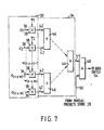
- the partial products store 28 is shown as comprising two parts; a partial products store (data) 28A and a partial products store (coefficients) 28B. Additionally, there is provided a summing means 150, an adder 151, a coefficient switch 152 ganged with the data switch 54, and a scaling means 153. The n x m lines 40 are connected to the summing means 150 so that the summing means 150 receives and sums each set of weighting coefficients supplied by the weighting coefficient calculator 32.
- the resulting sum is supplied to the adder 151 where it is added to the existing weighting coefficient sum (if any) held in the partial products store (coefficients) 28B, and the sum then resulting is returned to the partial products store (coefficients) 28B via the coefficient switch 152.
- a running total of the weighting coefficients is held in the partial products store (coefficients) 28B corresponding to the running total of the digital data words held in the partial products store (data) 28A.
- the scaling means 153 When the required filtered digital word is to be supplied by the data switch 54 to the line 56, it is in fact supplied via the scaling means 153, which also receives the corresponding running total of weighting coefficients via the coefficient switch 152.
- the scaling means 153 divides the digital word by the total of the weighting coefficients. In other words, the scaling means 153 adjusts the amplitude of the signal represented by the digital word to correct for any divergence from one in the sum of each set of weighting coefficients.
- the control means 60 determines that the filter arrangement should operate in a zero/low compression mode if the values of both the vertical and horizontal compression factors VCF and HCF lie between 1:1 (zero compression) and 2:1.
- the control means 60 causes the data switch 54 to remain all the time in the illustrated position. Also, the control means 60 does not cause the passage of data from the partial products store 28 to the adder 48, so that the intermediate words pass through the adder 48 unaltered. Further, the control means 60 causes selection from the family stored in the store 32 of a set of 16(n x m) weighting coefficients that will ensure, even for the maximum compression permitted in this mode, that the bandwidth of the filter will be such that aliasing due to compression is avoided or at least minimised. This same set of sixteen weighting coefficients is applied to the multiplier group 30 during each successive clock period or cycle.
- the prestore 22 is not used on this mode.
- the array store 26 loads a 4 x 4 array of sixteen samples or words of the input signal into the multiplier group 30.
- the filter arrangement operates in this mode in a similar manner to a conventional 2D-FIR in that the words of the array are multiplied by their respective weighting coefficients in the multiplier group 30 and the product words are summed in the summing means 34 to produce an intermediate word, the successive intermediate words being passed directly via the adder 48, the data switch 54 and the scaling means 153 ( Figure 16) to the output line 56.
- adjustment normalization
- the output words are the intermediate words and are produced at the same frequency (fs) as that at which the input words arrive. Intermediate words are not combined.
- Each successive output word is obtained by processing successive 4 x 4 arrays of input words spaced in the horizontal direction by one word, such as those designate A1, A2 and A3 in Figure 17.
- the control means 60 causes the filter arrangement to switch into this mode when it detects that the horizontal compression factor HCF has a value greater than 2:1 (but less than 3:1).
- an output word corresponding to filtration over an 8 x 4 (2n x m) sample array is produced at every alternate clock period.
- the same 4 x 4 array of sixteen input words is presented to the multiplier group 30 during a cycle comprising two consecutive clock periods.
- the set of sixteen weighting coefficients employed will of course change in dependence upon whether that 4 x 4 array is to form the left-hand or right-hand half of an 8 x 4 array.
- the control means 60 causes the store 32 to supply two different sets of sixteen weighting coefficients to the multiplier group 30 during alternate clock cycles.
- the vlues of the weighting coefficients are such as to cause the adoption of a restricted bandwidth which will prevent or at least reduce aliasing due to compression.
- the array store 26 loads into the multiplier group 30 a further 4 x 4 array of input words, this further array being displaced in the horizontal direction by two words with respect to the previous array. This process is repeated indefinitely.
- the 4 x 4 array A1 is processed twice (with different sets of sixteen weighting coefficients each time) to produce a pair of intermediate words W1a and W1b.
- the intermediate word W1a is combined in the adder 48 with an intermediate word previously stored in the partial products store 28 to form an output word which is passed via the data switch 54 to the scaling means 153 and the output line 56.
- the intermediate word W1b is passed to the partial products store 28 via the data switch 54 and the line 58, no output word being generated during the corresponding clock period.
- the 4 x 4 array A3 is processed twice (with the same two different sets of 16 weighting coefficients as in the first cycle) to produce a pair of intermediate words W3a and W3b, the intermediate word W3a being combined with a previously stored intermediate word in the adder 48 to produce an output word and the intermediate word W3b being sent to the partial products store 28.
- This process continues, and is illustrated for a number of consecutive clock periods by Table 1 below.
- the control means 60 causes the filter arrangement to switch into this mode when it detects that the horizontal compression factor HCF has exceeded 3:1.
- an output word corresponding to filtration over a 12 x 4 (3n x m) sample array is produced for every third clock period.
- a different 4 x 4 array of input words or samples is presented to the multiplier group 30 during each clock period, the successive arrays being spaced by one work in the horizontal direction, as in mode 1.
- three different sets of sixteen weighting coefficients are employed in turn over a cycle comprising three clock periods.
- the clock periods 1 to 3, 4 to 6, 7 to 9 etc. correspond to the cycles during which the 4 x 4 arrays processed correspond, respectively, to the left-hand, central and right-hand portions of the 12 x 4 array on which an output word is based.
- control means 60 causes some intermediate words to be added to previous intermediate words and the resultant sums to be added to subsequently generated intermediate words to generate output words. For instance, W1 is added to W5, the sum is stored, and the sum is added later to W9 to produce an output word. W1 and W5 can be summed in the adder 48 by passing W1 back from the store 28 to the adder W5 as W5 is generated, the summed word being directed back to the store 28 by the data switch 54.
- W1 and W5 can be summed in the adder 48 by passing W1 back from the store 28 to the adder W5 as W5 is generated, the summed word being directed back to the store 28 by the data switch 54.
- the techniques described under modes 2 and 3 above can be extended to deal with higher values of the horizontal compression factor HCF.
- the threshold values of HCF at which, as it increases, the filter arrangement steps into a different mode may generally be selected as desired. It is possible to step into a different mode each time that HCF is incremented by one. However, particularly for higher values of N, it is possible for the mode not to be stepped so frequently. It may for example be satisfactory to step into a different mode each time that HCF increases to a value such that the bandwidth of the filter arrangement is reduced by one octave with respect to its value for the previous (larger bandwidth) mode.
- the storage demands made on the partial products store 28 are minimal. That is, it is in general necessary to store only a few partial products (intermediate words) for a time which is much less than the length of a line. as will be explained below, the demands made on the partial products store 28 in the case of vertical compression are more extensive.
- the control means 60 causes the filter arrangement to switch into this mode when it detects that the vertical compression factor VCF is greater than 2:1 (but less than 3:1) and the horizontal compression factor is less than 2:1.
- the filter arrangement operates in the mode in a manner closely analogous to the 2:1 horizontal compression mode (mode 2), except that in this case each output word is based on a 4 x 8 (n x 2m) array comprising two vertically adjacent 4 x 4 arrays (for example two arrays designated A(1,1) and A(1,5) in Figure 19) rather than being based on an 8 x 4 (2n x m) array comprising two horizontally adjacent 4 x 4 arrays (for example the arrays A1 and A5 of Figure 18). Since vertically adjacent 4 x 4 arrays are spaced temporally by a plurality of lines (rather than by a plurality of clock periods), the operation of the filter arrangement in the case of vertical compression differs from the operation in the case of horizontal compression in three respects.
- the intervals employed in calculating intermediate words or partial products which are sent to storage comprise multiples of whole lines. (Therefore, in the case of 2:1 vertical compression, no output words are produced during alternate lines).
- the partial products store 28 since partial products are generated for a whole line, the partial products store 28 must have a capacity of at least one line (in fact, in the present mode, at least two lines).
- the pre-store 22 since (as explained below) the filter makes two passes through groups of four lines, the pre-store 22 must be capable of serving as a buffer store to accumulate for subsequent use that part of the input signal that arrives during this process.
- the filter arrangement processes the arrays shown at A(1,1), A(2,1), A(3,1) etc. in Figure 19, namely those arrays obtained by shifting through lines 1 to 4 of Figure 19 by increments of one clock period (one word or sample) in the horizontal direction.
- a set of sixteen weighting coefficients corresponding to the lower half of the 4 x 8 array on which the output words are based is employed during each clock period.
- the intermediate word produced at each clock period is combined with a stored intermediate word corresponding to the vertically adjacent 4 x 4 array to produce an output word based on a 4 x 8 array. Therefore, during this process, which takes up one full line, an output word is produced for every clock period.
- the filter processes the same arrays (lines 1 to 4) again, but using a different set of sixteen weighting coefficients corresponding to the upper half of the 4 x 8 array. All of the intermediate words produced in this process, which take up one full line, are stored in the partial products store 28, and no output words are produced.
- the filter then jumps two lines and performs two like processes on line 3 to 6 of Figure 19 (starting with the array A(1,3)), thereby again producing intermediate words for storage (but no output words) during one line and producing an output word at each clock period during another line.
- the filter then jumps two further lines and performs the same pair of processing operations on lines 4 to 8 in Figure 19 (starting with the array (1,5); and so on.
- the first line of output words would be formed by combining the words of the sub-totals (lines of intermediate words) L1sa and L1sb, where, referring to Figure 19, the sub-total L1sa comprises the intermediate words formed by processing the arrays A(1,1) etc. (lines 1 to 4) with the set of weighting coefficients corresponding to the upper half of the 4 x 8 array and the sub-total L1sb comprises the intermediate words formed by processing the arrays A(1,5) etc. (lines 5 to 8) with the set of weighting coefficients corresponding to the lower half of the 4 x 8 array.
- the maximum number of line stores required for this particular configuration in this particular mode in any one line is one for the prestore 24, four for the array store 26 and two for the partial products store 28, making a total of seven line stores. (See, for example, lines 9 and 11). With the provision of these seven line stores, a filter having a basic 4 x 4 configuration is modified to form a filter arrangement that effectively has a 4 x 8 configuration.
- the control means 60 causes the filter arrangement to enter this mode when it detects that both the vertical and horizontal compression factors are greater than 2:1, but less than 3:1.
- each output word is based upon an 8 x 8 array corresponding to four adjacent 4 x 4 arrays, for example those designated A(1,1), A(5,1), A(1,5) and A(5,5) in Figure 20.
- mode 5 (2:1 vertical compression with no horizontal compression)
- no output words are produced during alternate lines.
- mode 2 (2:1 horizontal compression)
- output words are produced only at alternate clock periods.
- this mode comprises a combination of modes 2 and 5, and might for example be performed as follows.
- lines 1 to 4 are processed twice.
- the arrays processed in this mode are not all of the arrays A(1,1), A(2,1), A(3,1) etc.
- each alternate 4 x 4 array A(1,1), A(3,1) etc. is processed four times altogether with four different sets of weighting coefficients, since each such 4 x 4 array will correspond to a respective different portion of four different 8 x 8 arrays on which four corresponding output words are based.
- each alternate array is processed twice (during two consecutive clock periods or cycles) to produce two intermediate words.
- One of these intermediate words or partial products is added in the adder 48 to a stored partial product retrieved from the partial products store 28, which stored partial product is the sum of three previous partial products corresponding to 3/4 of an 8 x 8 array on which an output word is to be based, to produce the output word.
- the other intermediate word is added in the adder 48 to a stored partial product (the sum of two previous partial products corresponding to the upper half of an 8 x 8 array on which an output word is to be based) retrieved from the partial products store 28 and the sum or partial product resulting from the addition is returned to the partial products store 28.
- That partial product is retrieved from the partial products store 28 two clock periods later and added to a newly generated partial product to form an output word as just described.
- one output word is produced at every alternate clock period.
- each alternate array is processed twice (during two consecutive clock periods or cycles) to produce two intermediate words.
- Each of these is sent to the partial products store 28 and retrieved therefrom two clock periods later to be added to a newly generated intermediate word and sent back to store.
- no output words are produced during this second processing operation.
- the partial products store 28 stores a number of partial products produced from this operation, which number is equal to the number of samples per line.
- each such stored partial product corresponds to the upper half (4 x 4) of a 4 x 8 array on which an output word is to be based
- each such stored partial product corresponds to the upper half (8 x 4) of an 8 x 8 array on which an output word is to be based.
- each such partial product (which corresponds to the upper half of an 8 x 8 array) is recalled and added to a newly generated partial product to produce a new partial product which corresponds to 3/4 of an 8 x 8 array, that new partial product is sent back to the partial products store 28 and, two clock periods later, it is retrieved from the partial products store 28 and added to a newly generated partial product to produce an output word.
- the amount of storage required in the partial products store 28 to cater for 2:1 vertical and horizontal compression is no greater than that required to cater for 2:1 vertical compression alone. Therefore, in the case of 2:1 compression in both the horizontal and vertical directions, the total storage requirement does not exceed the requirement of seven lines stores necessary in the case of 2:1 vertical compression with no horizontal compression.
- the control means 60 causes the filter arrangement to enter this mode when it detects that the vertical compression factor VCF is greater than 3:1.
- output words based upon 4 x 12 arrays are produced only during every third line, no output words being produced during the other lines.
- one word will be produced for every clock period in the case of less than 2:1 horizontal compression and a lesser number of words will be produced in the case of greater than 2:1 horizontal compression, in which latter case the horizontal size of the output array will of course be a multiple of four.
- the prestore 24 is not required because it is not necessary (as in mode 5) to supply each group of four lines to the filter twice, that is for two consecutive lines of the input signal, and then to jump two lines ahead. Instead, the four lines supplied from the array store 26 to the multiplier group are incremented by one line for each line of the input signal.
- control means 60 causes some sub-totals (lines of intermediate words) to be added to previously generated and stored sub-totals and the resultant sub-totals to be added to subsequently generated sub-totals to generate lines of output words.
- L3sa is generated and stored in line 10.
- L3sb is generated subsequently (in line 14) and the words thereof are added to those of L3sa (recalled from the store 28) as L3sb is generated, as in mode 6.
- the resultant sub-total (L3sa + L3sb) is not outputted to the output line 56, but is instead routed back to the store by the data switch 54.
- L3sc is generated in line 18
- the sub-total (L3sa + L3sb) is called back from the store 28 and the words thereof are added to L3sc to produce output line 3.
- such intermediate summations of intermediate sub-totals will be necessary also when the vertical compression factor is greater than in the present mode.
- the maximum number of line stores required for this particular configuration in this particular mode in any one line is four for the array store 26 and three for the partial products store 28, making a total of seven line stores.
- a filter having a basic 4 x 4 configuration is modified to form a filter arrangement that effectively has a 4 (at least) x 12 configuration.
- the control means 60 causes the filter arrangement to enter this mode when it detects that the vertical compression factor VCF is greater than 4:1.
- output words based upon 4 x 16 arrays are produced only during every fourth line, no output words being produced during the other lines.
- one word will be produced for every clock period in the case of less than 2:1 horizontal compression and a lesser number of words will be produced in the case of greater than 2:1 horizontal compression, in which latter case the horizontal size of the output array will of course be a multiple of four.
- the prestore 24 is needed and should be capable of storing temporarily up to three lines of the input signal. This is necessary because, in this mode, each group of four lines is passed through the filter four times and the array store 26 then jumps four lines ahead, so that the intervening three lines must temporarily be stored.
- the maximum number of line stores required for this particular configuration in this particular mode in any one line is three for the prestore 24, four for the array store 26 and three for the partial products store 28 (for example in line 19), or two for the prestore 24, four for the array store 26 and four for the pratial products store 28 (for example in line 18), in both cases making a total of ten line stores.
- a filter having a basic 4 x 4 configuration is modified to form a filter arrangement that effectively has a 4(at least) x 16 configuration.
- the control means 60 causes the filter arrangement to enter this mode when it detects that the vertical compression factor is greater than 8:1.
- output words based upon 4 x 32 arrays are produced only during every eighth line, no output words being produced during the other lines.
- one word will be produced for every clock period in the case of less than 2:1 horizontal compression and a lesser number of words will be produced in the case of greater than 2:1 horizontal compression, in which latter case the horizontal size of the output array will of course be a multiple of four.
- the prestore 24 functions in exactly the same way as in mode 8 because, again as in mode 8, each group of four lines is passed through the filter four times and the array store 26 then jumps four lines ahead.
- a filter having a basic 4 x 4 configuration is modified to form a filter arrangement that effectively has a 4(at least) x 32 configuration.
- modes 5 to 9 can be extended to deal with higher values of the vertical compression factor VCF. It is particularly important to note that the maximum line storage requirement of ten line stores derived in modes 8 and 9 represents a maximum or ceiling value. That is, for vertical compression factors which are still higher, no more than ten line stores should be required. Bearing in mind that, as indicated above, horizontal compression requires no additional partial product storage, it follows that the present configuration of filter arrangement can deal with indefinitely higher vertical and horizontal compression factors without requiring any more storage than that provided by the ceiling value of ten line stores.
- the threshold value of the vertical compression factor VCF at which, as it increases, the filter arrangement steps into a different mode may generally be selected as desired. It is possible to step into a different mode each time that VCF is incremented by one. However, particularly for higher values of N, it is possible for the mode not to be stepped so frequently. It may for example be satisfactory to step into a different mode each time that VCF increases to a value such that the bandwidth of the filter arrangement is reduced by one octave with respect to its value for prvious (larger bandwidth) mode.
- the variations of the horizontal and vertical compression factors can be effected independently of one another. That is, for a particular horizontal (or vertical) compression factor required by the DVE unit, the filter arrangement will respond appropriately to any vertical (or horzontal) compression factor required by the DVE unit.
- the memory 22 need comprise a maximum of ten line stores. These are shown in Figure 21 at LS1 to LS10. Each line store effectively operates a shift register and has a number of stages equal to the number of samples per line (for example 864) in the input signal, each stage being able to handle a number of bits equal to the number of bits (for example eight) per sample of the input signal.
- the prestore 24 is shown as being constituted by the line stores L1 to L3.
- the input input image signal line 20 is connected to an input to the line store LS1.
- An output of the line store LS1 is connected to an input of the line store LS2 and an output of the line store LS2 is connectable to an input of the line store LS3 via a switch SW1. Accordingly, with the switch SW1 positioned to connect the line stores LS1 to LS3 in tandem, the input samples are clocked through them so that, during three lines of the input signal, these three lines become stored in the line stores LS1 to LS3.
- the array store 26 is constituted by the line stores LS4 to LS7.
- the three stores LS4 to LS6 are memory mapped to the line stores LS1 to LS3 of the prestore 22 so that the contents of the stores LS1 to LS3 can be memory mapped into the stores LS4 to LS6 when required.
- the line store LS7 of the array store 26 is connected directly to the input image signal line 20 because, as explained above in the description of modes 5 and 8, only a maximum of three lines need to be pre-stored so that the fourth line can be fed directly into the array store.
- the partial products store 28 is constituted by the three stores LS8 to LS10 which are connected in tandem as shown so that sub-totals (lines of intermediate products) arriving on the line 58 from the data switch 54 are shifted therethrough.
- An output from the final line store LS8 of the partial products store 28 is connectable to the line 50 leading to the adder 48 via a switch SW2.
- the output of the line store LS8 is connectable also, via the switch SW1, to the input of the line store LS3 of the prestore LS3, and an output of the line store LS3 is connectable to the line 50 via the switch SW2.
- the switches SW1 and SW2 are actuated by the control means 60 via the line 62.
- the line store LS3 is switched by the control means 60 between the prestore 24 and the partial products store 28 as required.
- the line store LS3 forms part of the prestore 24, as shown in Figure 21, whereas in a second position it forms part of the partial products store 28.
- the output of the line store LS2 is connected to the input of the line store LS3 via the switch SW1 and the line store LS8 is connected to the line 50 via the switch SW2.
- the line store LS3 is connected in tandem with the line stores LS8 to LS10 via the switch SW1 and the output of the line store LS3 is connected to the line 50 via the switch SW2.
- a basic figure of merit for the filter arrangement depends upon the amount of rejection of alias components in the zero/low compression mode (mode 1 above) with the highest compression permissible in that mode, that is just before it switches to a mode in which there is more than 2:1 compression in the vertical and/or horizontal direction, since under this condition the filter arrangement is in its most primitive form.
- the figure of merit depends in turn on the basic array size in the sense that the figure of merit increases with an increase (in either or both directions) of the basic array size.
- n and m the array sizes in the horizontal and vertical directions, respectively
- the 2D-FIR filter described with reference to Figures 5 to 21 can be used with a compression means which is in the form of a digital video effects (DVE) unit.
- a DVE unit may require that the horizontal and/or vertical compression factor be changed over the image (for example a field of a television signal) in that it may be desired to achieve a video effect that calls for variation of the compression factors over different parts of the manipulated version of the image signal generated by the DVE unit. Therefore, in such cases, it is desired to carry out what can be termed dynamic control of the characteristics of the filter arrangement.
- Figures 22 and 23 show respective enhancements to the 2D-FIR filter as shown in Figue 6 which enable compensation for the variable delay mentioned in (i) above.
- the 2D-FIR filter shown in Figure 22 corresponds to that shown in Figure 6, except that the output line 56 is connected to a variable delay store 80, which is under the control of the control means 60 via a line 82, and the output signal of the filter arrangement is developed on an output line 84 from the variable delay store 80.
- the variable delay store 80 delays the output signal on the line 56 by an amount depending upon the mode of operation of the filter arrangement (and therefore the propagation delay therethrough), such that, regardless of the mode selected, there will always be a predetermined delay between the input signal on the line 20 and the output signal on the line 84.
- the 2D-FIR filter arrangement shown in Figure 23 corresponds to that shown in Figure 6, with the following modifications.
- the output line 56 is connected to an input of a field store 86, which may be a field store of a DVE unit which is fed with the input image signal after it has been filtered.
- the memory 22 includes an address store 88 which is supplied with input addresses on a line 90.
- the address store 88 is controlled by the control means 60 via a line 92. Addresses are supplied from the address store 88 to the field store 86 via a line 94.
- field store address information generated by the DVE unit is passed by the DVE unit into the address store 88 via the line 90.
- the control means 60 is operative to identify the central point of each filter array (once per ouput sample) and to store the coincident address which is then supplied via the line 94 to the field store 86 as the corresponding output sample is supplied to the field store 86 via the line 56.
- the address may be considered as an inactive partial product and the maximum storage required is in fact four lines. It should be noted that the delay through the filter rapidly becomes significant in terms of the field period as the effective array size of the filter arrangement gets larger. However, the largest array would need only to access the whole field of data and it could achieve this in a period far less than one field period, whereby no further delay compensation would be required.
- the invention is also applicable, for example, to filter arrangements which do not have provision for recycling partial products; to filter arrangements in which the sample array size is variable; and generally to filter arrangements operating as interpolators by two-dimensionally filtering a signal which represents an image and comprises a sequence of digital words.
Applications Claiming Priority (2)
| Application Number | Priority Date | Filing Date | Title |
|---|---|---|---|
| GB8627417 | 1986-11-17 | ||
| GB8627417A GB2197766B (en) | 1986-11-17 | 1986-11-17 | Two-dimensional finite impulse response filter arrangements |
Publications (3)
| Publication Number | Publication Date |
|---|---|
| EP0268408A2 true EP0268408A2 (fr) | 1988-05-25 |
| EP0268408A3 EP0268408A3 (en) | 1989-11-29 |
| EP0268408B1 EP0268408B1 (fr) | 1993-03-24 |
Family
ID=10607460
Family Applications (1)
| Application Number | Title | Priority Date | Filing Date |
|---|---|---|---|
| EP87309812A Expired - Lifetime EP0268408B1 (fr) | 1986-11-17 | 1987-11-05 | Arrangements de filtrage à réponse impulsionnelle finie à deux dimensions |
Country Status (5)
| Country | Link |
|---|---|
| US (1) | US4805129A (fr) |
| EP (1) | EP0268408B1 (fr) |
| JP (1) | JP2629748B2 (fr) |
| DE (1) | DE3785002T2 (fr) |
| GB (1) | GB2197766B (fr) |
Cited By (3)
| Publication number | Priority date | Publication date | Assignee | Title |
|---|---|---|---|---|
| DE3841268A1 (de) * | 1988-12-08 | 1990-06-13 | Thomson Brandt Gmbh | Digitales filter |
| EP0620681A2 (fr) * | 1993-04-12 | 1994-10-19 | Matsushita Electric Industrial Co., Ltd. | Traitement d'un signal vidéo |
| US5751374A (en) * | 1993-04-12 | 1998-05-12 | Matsushita Electric Industrial Co., Ltd. | Processing of pixel data according to different broadcasting systems |
Families Citing this family (70)
| Publication number | Priority date | Publication date | Assignee | Title |
|---|---|---|---|---|
| JPS63205778A (ja) * | 1987-02-20 | 1988-08-25 | Sumitomo Electric Ind Ltd | ビデオ信号デイジタル化回路 |
| JP2639543B2 (ja) * | 1987-12-02 | 1997-08-13 | 日本ビクター株式会社 | デジタル・フィルタ装置 |
| DE58905114D1 (de) * | 1988-06-13 | 1993-09-09 | Siemens Ag | Verfahren zur stoerunterdrueckung bei ultraschall-abstandsmessungen. |
| US5201029A (en) * | 1988-10-24 | 1993-04-06 | U.S. Philips Corporation | Digital data processing apparatus using daisy chain control |
| EP0372950B1 (fr) * | 1988-12-08 | 1995-07-05 | Canon Kabushiki Kaisha | Appareil pour la réduction d'images |
| US5293459A (en) * | 1988-12-23 | 1994-03-08 | U.S. Philips Corporation | Neural integrated circuit comprising learning means |
| JP2533942B2 (ja) * | 1989-03-13 | 1996-09-11 | 株式会社日立製作所 | 知識抽出方法およびプロセス運転支援システム |
| GB2244622B (en) * | 1990-05-30 | 1994-06-15 | Sony Corp | Image signal processing |
| US5101446A (en) * | 1990-05-31 | 1992-03-31 | Aware, Inc. | Method and apparatus for coding an image |
| WO1991019272A1 (fr) * | 1990-05-31 | 1991-12-12 | Aware, Inc. | Systeme ameliore de compression d'images |
| US6693951B1 (en) * | 1990-06-25 | 2004-02-17 | Qualcomm Incorporated | System and method for generating signal waveforms in a CDMA cellular telephone system |
| US5659569A (en) * | 1990-06-25 | 1997-08-19 | Qualcomm Incorporated | Data burst randomizer |
| US5634087A (en) * | 1991-02-28 | 1997-05-27 | Rutgers University | Rapidly trainable neural tree network |
| US5796859A (en) * | 1991-10-08 | 1998-08-18 | Computed Anatomy Incorporated | Processing of keratoscopic images employing local spatial phase |
| US5818957A (en) * | 1991-10-08 | 1998-10-06 | Computed Anatomy Incorporated | Processing of keratoscopic images |
| US5233549A (en) * | 1992-04-21 | 1993-08-03 | Loral Aerospace Corp. | Reduced quantization error FIR filter |
| US5367476A (en) * | 1993-03-16 | 1994-11-22 | Dsc Communications Corporation | Finite impulse response digital filter |
| JPH07168809A (ja) * | 1993-03-30 | 1995-07-04 | Klics Ltd | ウェーブレット変換方法及びウェーブレット変換回路 |
| US5546477A (en) * | 1993-03-30 | 1996-08-13 | Klics, Inc. | Data compression and decompression |
| AUPM607994A0 (en) * | 1994-06-03 | 1994-06-30 | Masters, John | A data conversion technique |
| US5748786A (en) | 1994-09-21 | 1998-05-05 | Ricoh Company, Ltd. | Apparatus for compression using reversible embedded wavelets |
| JP3302229B2 (ja) | 1994-09-20 | 2002-07-15 | 株式会社リコー | 符号化方法、符号化/復号方法及び復号方法 |
| US5966465A (en) * | 1994-09-21 | 1999-10-12 | Ricoh Corporation | Compression/decompression using reversible embedded wavelets |
| US6873734B1 (en) * | 1994-09-21 | 2005-03-29 | Ricoh Company Ltd | Method and apparatus for compression using reversible wavelet transforms and an embedded codestream |
| US6195465B1 (en) | 1994-09-21 | 2001-02-27 | Ricoh Company, Ltd. | Method and apparatus for compression using reversible wavelet transforms and an embedded codestream |
| US5881176A (en) | 1994-09-21 | 1999-03-09 | Ricoh Corporation | Compression and decompression with wavelet style and binary style including quantization by device-dependent parser |
| US6549666B1 (en) | 1994-09-21 | 2003-04-15 | Ricoh Company, Ltd | Reversible embedded wavelet system implementation |
| US6229927B1 (en) | 1994-09-21 | 2001-05-08 | Ricoh Company, Ltd. | Reversible embedded wavelet system implementation |
| US6310963B1 (en) | 1994-09-30 | 2001-10-30 | Sensormatic Electronics Corp | Method and apparatus for detecting an EAS (electronic article surveillance) marker using wavelet transform signal processing |
| GB2305052B (en) * | 1995-09-08 | 2000-04-05 | Quantel Ltd | An image processing system |
| US5881180A (en) * | 1996-02-08 | 1999-03-09 | Sony Corporation | Method and apparatus for the reduction of blocking effects in images |
| US5822232A (en) * | 1996-03-01 | 1998-10-13 | Intel Corporation | Method for performing box filter |
| US5974196A (en) * | 1996-03-15 | 1999-10-26 | Sony Corporation | Method and apparatus for blocking effect reduction in images |
| US5933542A (en) * | 1996-04-24 | 1999-08-03 | Sony Corporation | Method and apparatus for blocking effect reduction in images by post-processing in the spatial domain |
| US5835630A (en) * | 1996-05-08 | 1998-11-10 | Xerox Corporation | Modular time-varying two-dimensional filter |
| US5796875A (en) * | 1996-08-13 | 1998-08-18 | Sony Electronics, Inc. | Selective de-blocking filter for DCT compressed images |
| US5999656A (en) * | 1997-01-17 | 1999-12-07 | Ricoh Co., Ltd. | Overlapped reversible transforms for unified lossless/lossy compression |
| US6032168A (en) * | 1997-08-15 | 2000-02-29 | Motorola, Inc. | Computer system to perform a filter operation using a logarithm and inverse-logarithm converter and methods thereof |
| US5909271A (en) * | 1997-10-24 | 1999-06-01 | Computed Anatomy, Incorporated | Device for performing ophthalmic procedures with improved alignment |
| US5988815A (en) * | 1997-10-24 | 1999-11-23 | Tomey Co., Ltd. | Pattern illumination device |
| DE69808798T2 (de) | 1997-12-19 | 2003-09-18 | Bae Systems Plc Farnborough | Digitales signalfilter unter verwendung von ungewichteten neuralen techniken |
| US6044172A (en) * | 1997-12-22 | 2000-03-28 | Ricoh Company Ltd. | Method and apparatus for reversible color conversion |
| FR2790322A1 (fr) * | 1999-02-26 | 2000-09-01 | Koninkl Philips Electronics Nv | Recepteur, circuit programmable et procede de calcul de filtres numeriques |
| US6314452B1 (en) | 1999-08-31 | 2001-11-06 | Rtimage, Ltd. | System and method for transmitting a digital image over a communication network |
| US6393154B1 (en) | 1999-11-18 | 2002-05-21 | Quikcat.Com, Inc. | Method and apparatus for digital image compression using a dynamical system |
| US20010047516A1 (en) * | 2000-02-01 | 2001-11-29 | Compaq Computer Corporation | System for time shifting live streamed video-audio distributed via the internet |
| WO2001080561A1 (fr) * | 2000-04-18 | 2001-10-25 | Rtimage Inc. | Systeme et procede destines a la lecture d'images en continu, progressivement et sans perte via un reseau de communication |
| GB0026846D0 (en) * | 2000-11-03 | 2000-12-20 | Clayton John C | Motion compensation of images |
| AU2002229090A1 (en) * | 2000-12-14 | 2002-06-24 | Rtimage Inc. | Three-dimensional image streaming system and method for medical images |
| US6898323B2 (en) | 2001-02-15 | 2005-05-24 | Ricoh Company, Ltd. | Memory usage scheme for performing wavelet processing |
| US7006697B1 (en) | 2001-03-30 | 2006-02-28 | Ricoh Co., Ltd. | Parallel block MQ arithmetic image compression of wavelet transform coefficients |
| US6859563B2 (en) | 2001-03-30 | 2005-02-22 | Ricoh Co., Ltd. | Method and apparatus for decoding information using late contexts |
| US6950558B2 (en) * | 2001-03-30 | 2005-09-27 | Ricoh Co., Ltd. | Method and apparatus for block sequential processing |
| US6895120B2 (en) * | 2001-03-30 | 2005-05-17 | Ricoh Co., Ltd. | 5,3 wavelet filter having three high pair and low pair filter elements with two pairs of cascaded delays |
| US7062101B2 (en) | 2001-03-30 | 2006-06-13 | Ricoh Co., Ltd. | Method and apparatus for storing bitplanes of coefficients in a reduced size memory |
| US7581027B2 (en) * | 2001-06-27 | 2009-08-25 | Ricoh Co., Ltd. | JPEG 2000 for efficent imaging in a client/server environment |
| US7142729B2 (en) * | 2001-09-10 | 2006-11-28 | Jaldi Semiconductor Corp. | System and method of scaling images using adaptive nearest neighbor |
| CA2360295A1 (fr) * | 2001-10-26 | 2003-04-26 | Jaldi Semiconductor Corp. | Systeme et methode de gauchissement d'images |
| US7007052B2 (en) * | 2001-10-30 | 2006-02-28 | Texas Instruments Incorporated | Efficient real-time computation |
| US7280252B1 (en) | 2001-12-19 | 2007-10-09 | Ricoh Co., Ltd. | Error diffusion of multiresolutional representations |
| US6624688B2 (en) * | 2002-01-07 | 2003-09-23 | Intel Corporation | Filtering variable offset amplifer |
| US7095907B1 (en) | 2002-01-10 | 2006-08-22 | Ricoh Co., Ltd. | Content and display device dependent creation of smaller representation of images |
| US6650184B2 (en) | 2002-03-15 | 2003-11-18 | Intel Corporation | High gain amplifier circuits and their applications |
| US7120305B2 (en) * | 2002-04-16 | 2006-10-10 | Ricoh, Co., Ltd. | Adaptive nonlinear image enlargement using wavelet transform coefficients |
| JP4282286B2 (ja) * | 2002-08-22 | 2009-06-17 | 富士通株式会社 | ディジタルフィルタ装置 |
| JP4286124B2 (ja) * | 2003-12-22 | 2009-06-24 | 三洋電機株式会社 | 画像信号処理装置 |
| US20060212502A1 (en) * | 2004-12-30 | 2006-09-21 | General Instruments Corporation | Method and apparatus for implementing digital filters |
| US7619639B1 (en) * | 2005-09-12 | 2009-11-17 | Nvidia Corporation | Adaptive scaling using a programmable video engine |
| US8983218B2 (en) | 2012-04-11 | 2015-03-17 | Texas Instruments Incorporated | Virtual boundary processing simplification for adaptive loop filtering (ALF) in video coding |
| US10902572B1 (en) | 2019-10-09 | 2021-01-26 | Karl Storz Imaging, Inc. | Enhanced fluorescence imaging for imaging system |
Family Cites Families (3)
| Publication number | Priority date | Publication date | Assignee | Title |
|---|---|---|---|---|
| US4736448A (en) * | 1984-03-31 | 1988-04-05 | Kabushiki Kaisha Toshiba | Spatial filter |
| JPH0738217B2 (ja) * | 1985-04-18 | 1995-04-26 | ファナック株式会社 | 空間積和演算装置 |
| GB2183118B (en) * | 1985-11-19 | 1989-10-04 | Sony Corp | Image signal processing |
-
1986
- 1986-11-17 GB GB8627417A patent/GB2197766B/en not_active Expired - Lifetime
-
1987
- 1987-10-20 US US07/110,452 patent/US4805129A/en not_active Expired - Fee Related
- 1987-11-05 EP EP87309812A patent/EP0268408B1/fr not_active Expired - Lifetime
- 1987-11-05 DE DE8787309812T patent/DE3785002T2/de not_active Expired - Lifetime
- 1987-11-17 JP JP62290356A patent/JP2629748B2/ja not_active Expired - Fee Related
Non-Patent Citations (2)
| Title |
|---|
| THE TRANSACTIONS OF THE IECE OF JAPAN, vol. E62, no. 4, April 1979, pages 291-292, Tokyo, JP; H. KATO et al.: "A method of designing two-dimensional FIR filters using a reconstruction technique" * |
| THE TRANSACTIONS OF THE IECE OF JAPAN, vol. E63, no. 12, December 1980, pages 849-854, Tokyo, JP; H. KATO et al.: "Designing of two-dimensional FIR fan filters by Fourier reconstruction" * |
Cited By (8)
| Publication number | Priority date | Publication date | Assignee | Title |
|---|---|---|---|---|
| DE3841268A1 (de) * | 1988-12-08 | 1990-06-13 | Thomson Brandt Gmbh | Digitales filter |
| US5025406A (en) * | 1988-12-08 | 1991-06-18 | Deutsche Thomson-Braudt Gmbh | Adaptive digital filter for multi path distortion cancellation |
| EP0620681A2 (fr) * | 1993-04-12 | 1994-10-19 | Matsushita Electric Industrial Co., Ltd. | Traitement d'un signal vidéo |
| EP0620681A3 (fr) * | 1993-04-12 | 1995-03-01 | Matsushita Electric Ind Co Ltd | Traitement d'un signal vidéo. |
| US5751374A (en) * | 1993-04-12 | 1998-05-12 | Matsushita Electric Industrial Co., Ltd. | Processing of pixel data according to different broadcasting systems |
| US5751375A (en) * | 1993-04-12 | 1998-05-12 | Matsushita Electric Industrial Co., Ltd. | Processing of pixel data at an operating frequency higher than the sampling rate of the input signal |
| EP0876056A1 (fr) * | 1993-04-12 | 1998-11-04 | Matsushita Electric Industrial Co., Ltd. | Processeur de données vidéo et traitement de signaux vidéo |
| EP1320258A1 (fr) * | 1993-04-12 | 2003-06-18 | Matsushita Electric Industrial Co., Ltd. | Processeur de signal vidéo et traitement de signal vidéo |
Also Published As
| Publication number | Publication date |
|---|---|
| JP2629748B2 (ja) | 1997-07-16 |
| US4805129A (en) | 1989-02-14 |
| GB8627417D0 (en) | 1986-12-17 |
| DE3785002D1 (de) | 1993-04-29 |
| GB2197766B (en) | 1990-07-25 |
| DE3785002T2 (de) | 1993-08-19 |
| GB2197766A (en) | 1988-05-25 |
| JPS63132517A (ja) | 1988-06-04 |
| EP0268408A3 (en) | 1989-11-29 |
| EP0268408B1 (fr) | 1993-03-24 |
Similar Documents
| Publication | Publication Date | Title |
|---|---|---|
| EP0268408B1 (fr) | Arrangements de filtrage à réponse impulsionnelle finie à deux dimensions | |
| US4802110A (en) | Two-dimensional finite impulse response filter arrangements | |
| US4328426A (en) | Filter for image pixels | |
| US4760605A (en) | Image signal processing with filtering to account for image mapping | |
| US4715257A (en) | Waveform generating device for electronic musical instruments | |
| CA1298354C (fr) | Circuit a retard numerique continument variable | |
| KR100248021B1 (ko) | Csd 필터의 신호처리방법과 그 회로 | |
| KR100210730B1 (ko) | 디지탈 보간 회로 | |
| US5023825A (en) | Coefficient reduction in a low ratio sampling rate converter | |
| GB2212690A (en) | Anti-aliasing at image boundaries in special effects | |
| US5949695A (en) | Interpolator using a plurality of polynomial equations and associated methods | |
| US5475510A (en) | Method for transforming color signals and apparatus for the method | |
| US4328425A (en) | Filter for image pixels | |
| US5561723A (en) | Localized image compression calculation method and apparatus to control anti-aliasing filtering in 3-D manipulation of 2-D video images | |
| US5559905A (en) | Digital image resizing apparatus | |
| US4435774A (en) | Method of and arrangement for calculating the discrete Fourier transform by means of two circular convolutions | |
| JPH0313066A (ja) | 色修正方法及びその装置 | |
| US5928314A (en) | Digital filter having a substantially equal number of negative and positive weighting factors | |
| EP0103355B1 (fr) | Système de conversion analogique-numérique pour un signal vidéo | |
| US5233549A (en) | Reduced quantization error FIR filter | |
| JPH07120924B2 (ja) | 標本化周波数変換装置 | |
| JP2529229B2 (ja) | コサイン変換装置 | |
| JP3223280B2 (ja) | 波形データ補間装置 | |
| GB2307042A (en) | Sonar signal processing apparatus | |
| GB2126450A (en) | Time compression of sampled signals |
Legal Events
| Date | Code | Title | Description |
|---|---|---|---|
| PUAI | Public reference made under article 153(3) epc to a published international application that has entered the european phase |
Free format text: ORIGINAL CODE: 0009012 |
|
| AK | Designated contracting states |
Kind code of ref document: A2 Designated state(s): DE FR GB NL |
|
| PUAL | Search report despatched |
Free format text: ORIGINAL CODE: 0009013 |
|
| AK | Designated contracting states |
Kind code of ref document: A3 Designated state(s): DE FR GB NL |
|
| 17P | Request for examination filed |
Effective date: 19900324 |
|
| 17Q | First examination report despatched |
Effective date: 19920901 |
|
| GRAA | (expected) grant |
Free format text: ORIGINAL CODE: 0009210 |
|
| AK | Designated contracting states |
Kind code of ref document: B1 Designated state(s): DE FR GB NL |
|
| REF | Corresponds to: |
Ref document number: 3785002 Country of ref document: DE Date of ref document: 19930429 |
|
| ET | Fr: translation filed | ||
| PLBE | No opposition filed within time limit |
Free format text: ORIGINAL CODE: 0009261 |
|
| STAA | Information on the status of an ep patent application or granted ep patent |
Free format text: STATUS: NO OPPOSITION FILED WITHIN TIME LIMIT |
|
| 26N | No opposition filed | ||
| REG | Reference to a national code |
Ref country code: GB Ref legal event code: IF02 |
|
| PGFP | Annual fee paid to national office [announced via postgrant information from national office to epo] |
Ref country code: GB Payment date: 20061101 Year of fee payment: 20 |
|
| PGFP | Annual fee paid to national office [announced via postgrant information from national office to epo] |
Ref country code: DE Payment date: 20061102 Year of fee payment: 20 |
|
| PGFP | Annual fee paid to national office [announced via postgrant information from national office to epo] |
Ref country code: NL Payment date: 20061105 Year of fee payment: 20 |
|
| PGFP | Annual fee paid to national office [announced via postgrant information from national office to epo] |
Ref country code: FR Payment date: 20061108 Year of fee payment: 20 |
|
| REG | Reference to a national code |
Ref country code: GB Ref legal event code: PE20 |
|
| NLV7 | Nl: ceased due to reaching the maximum lifetime of a patent |
Effective date: 20071105 |
|
| PG25 | Lapsed in a contracting state [announced via postgrant information from national office to epo] |
Ref country code: NL Free format text: LAPSE BECAUSE OF EXPIRATION OF PROTECTION Effective date: 20071105 |
|
| PG25 | Lapsed in a contracting state [announced via postgrant information from national office to epo] |
Ref country code: GB Free format text: LAPSE BECAUSE OF EXPIRATION OF PROTECTION Effective date: 20071104 |