EP0268317A2 - Verfahren und Einrichtung zur Steuerung der Bahn eines geleiteten Organs - Google Patents
Verfahren und Einrichtung zur Steuerung der Bahn eines geleiteten Organs Download PDFInfo
- Publication number
- EP0268317A2 EP0268317A2 EP87202065A EP87202065A EP0268317A2 EP 0268317 A2 EP0268317 A2 EP 0268317A2 EP 87202065 A EP87202065 A EP 87202065A EP 87202065 A EP87202065 A EP 87202065A EP 0268317 A2 EP0268317 A2 EP 0268317A2
- Authority
- EP
- European Patent Office
- Prior art keywords
- bubble
- bubbles
- collision
- guard
- cluster
- Prior art date
- Legal status (The legal status is an assumption and is not a legal conclusion. Google has not performed a legal analysis and makes no representation as to the accuracy of the status listed.)
- Ceased
Links
Images

Classifications
-
- B—PERFORMING OPERATIONS; TRANSPORTING
- B25—HAND TOOLS; PORTABLE POWER-DRIVEN TOOLS; MANIPULATORS
- B25J—MANIPULATORS; CHAMBERS PROVIDED WITH MANIPULATION DEVICES
- B25J9/00—Program-controlled manipulators
- B25J9/16—Program controls
- B25J9/1674—Program controls characterised by safety, monitoring, diagnostic
- B25J9/1676—Avoiding collision or forbidden zones
-
- G—PHYSICS
- G05—CONTROLLING; REGULATING
- G05B—CONTROL OR REGULATING SYSTEMS IN GENERAL; FUNCTIONAL ELEMENTS OF SUCH SYSTEMS; MONITORING OR TESTING ARRANGEMENTS FOR SUCH SYSTEMS OR ELEMENTS
- G05B2219/00—Program-control systems
- G05B2219/30—Nc systems
- G05B2219/49—Nc machine tool, till multiple
- G05B2219/49145—Spheres replace object, check first collision for large spheres, then small
-
- Y—GENERAL TAGGING OF NEW TECHNOLOGICAL DEVELOPMENTS; GENERAL TAGGING OF CROSS-SECTIONAL TECHNOLOGIES SPANNING OVER SEVERAL SECTIONS OF THE IPC; TECHNICAL SUBJECTS COVERED BY FORMER USPC CROSS-REFERENCE ART COLLECTIONS [XRACs] AND DIGESTS
- Y02—TECHNOLOGIES OR APPLICATIONS FOR MITIGATION OR ADAPTATION AGAINST CLIMATE CHANGE
- Y02P—CLIMATE CHANGE MITIGATION TECHNOLOGIES IN THE PRODUCTION OR PROCESSING OF GOODS
- Y02P90/00—Enabling technologies with a potential contribution to greenhouse gas [GHG] emissions mitigation
- Y02P90/02—Total factory control, e.g. smart factories, flexible manufacturing systems [FMS] or integrated manufacturing systems [IMS]
Definitions
- the invention relates to a method for controlling a movement of a guided object in an environment to avoid collision with another object, the method comprising making predictions of a collision ahead of occurrence of the collision given the geometrical outlines of all objects involved, their relative positions, and their trajectories in an immediate future so that avoiding action can be taken, wherein each object is respresented by at least one spherical bubble of known radius and centre position which bubble contains at least partially the geometrical outline of the object, at least one object being represented by a cluster of interpenetrating spherical bubbles of at least two different radii, the outermost surface of the cluster containing the outermost surface of the object, wherein the collision between objects is predicted as a first estimated point of touch to occur between any bubble of the cluster with a bubble representing another object.
- Such a method is known from European Patent Application 87198, US Patent 4,578,757.
- the reference provides a simple regular, general way of representing the shape of an object which simplifies the collision prediction.
- the collision problem reduces to finding the earliest pair of bubbles to collide.
- the time and place of a collision between two bubbles can be found easily and exactly provided both bubbles are travelling with uniform velocity.
- the time at which the collision occurs is found by solving a quadratic equation having time as the independent variable. This equation has two roots. If they are imaginary, no collision occurs. Otherwise, the roots correspond to two times, and the earlier of these is the required answer.
- the later time is the time at which the bubbles would part again supposing that, instead of behaving like solid objects and colliding, they had passed through each other without deviating from their courses.
- Objects may not travel at uniform velocity because they can rotate and are subject to gravity and other forces.
- the constant velocity assumption may be sufficient for short-term predictions, which is the main concern in simulating the relative movement of objects.
- the representation of an object may be effected fully or partly. In the latter case the representation must be done as far as necessary, in that an actual collision would always be preceded by a collision with a representing bubble.
- one object could be represented by a single bubble. Alternatively, both or all objects are represented by a cluster of a plurality of bubbles.
- the prediction of the collision of two clusters of bubbles will involve a computation time proportional to the product of the numbers of bubbles in the two clusters. If there are 100 bubbles in each of two clusters, then 10,000 computations are needed.
- the cluster comprises at least one spherical guard bubble, each guard bubble containing a selection of the bubbles of that cluster, and in that any guard bubble from the cluster is examined for collision before further cluster bubbles are examined.
- a guard bubble is an imaginary bubble drawn around and completely enclosing a selected group of bubbles of the cluster. If there is no collision between guard bubbles, none of the further bubbles of the one or two clusters need be tested for collision, thereby avoiding computation for all those bubbles.
- the invention is characterized in that the cluster comprises a succession of levels of guard bubbles, in that each guard bubble of the innermost level contains a selection of the cluster bubbles such that the guard bubbles of the innermost level contain, between them, all the bubbles of the cluster and such that each bubble is assigned to only one innermost guard bubble, in that each guard bubble of a given level outside the innermost level encloses a selection of the guard bubbles of the adjacent inner level such that the guard bubbles of the given level contain, between them, all the guard bubbles of the adjacent inner level and such that a guard bubble of the adjacent inner level is assigned to only one guard bubble of the given level.
- a guard bubble may also contain all the bubbles of the cluster. Such a guard bubble then represents any object as a sphere which completely encloses the object.
- a pair of guard bubbles of a given level may overlap and both may contains parts of, or even all of, some of the inner bubbles. But each inner bubble is normally assigned to only one of the guard bubbles which completely encloses it.
- the successive levels represent the object with increasing precision. Also, at any level, the object is represented by a minimum amount of information sufficient for the purpose at that level.
- the calculation for collision between bubbles means finding the separation between bubbles and this involves the solution of a right-angled triangle which entails finding the square root of the difference of the squares of two sides of the triangle.
- the computer time involved in finding a square root is very much longer than the time taken to perform additions and multiplications. Since the predicted collision time between bubbles is an early prediction of the actual collision between objects, an early approximation to the time of collision between bubbles may be an acceptable alternative, particularly if it avoids a square root calculation.
- the invention is characterized in that the collision calculation comprises calculating the trajectory of a bubble of the representation of the guided object relative to a bubble of a representation of another object for a limited period of time as a straight line approximation at constant velocity, deriving an equation giving the square of the separation of the bubbles as a function of time during the limited period and calculating the time of collision of the bubbles as an early approximate solution of the equation by applying Newton's method of successive approximations.
- the equation expressing the square of the separation of the bubbles as a function of time is a simple quadratic equation and is therefore a parabola when graphed.
- the exact solution of the equation is given by the intersection of the graph with the time axis when the separation is zero and, when collision would occur between the bubbles. It will be recalled that Newton's approximation involves selecting a first approximate solution, drawing a tangent to the graph at this point, and finding where the tangent intersects the horizontal axis which gives an improved approximate solution.
- the slope of the parabola is a simple linear function of time which is easy to calculate.
- the calculation of the improved approximation only involves simple arithmetic operations, no square root being involved.
- the first approximate solution can be the present time. It is important to note that, with a parabolic curve, the improved solution will always be at a time earlier than the time at which the bubbles would actually collide. The approximate solutions found therefore always provide safe estimates of the time of collision. Newton's method may be repeated to find a more exact solution. But, given that the assumed straight line motion is itself an approximation for a limited time ahead, the time of collision may be calculated as the first approximate solution given by Newton's method. Thus the calculation time using Newton′s method is markedly reduced as compared with finding the exact solution by square root extraction.
- the invention provides an apparatus for controlling the movement of a guided object in an environment to avoid collision with another object, comprising movement means for guiding the guided object in the environment, means for measuring the position of the guided object relative to any other object, information storage means for storing the shape and size of the guided object and for storing the location, shape and size of any other object, and calculation means for taking the measured position of the guided object and the stored information on the guided object and on any other object, calculating a collision-free path for the guided object, and outputting control information to the movement means to realize said collision-free path, wherein the stored information on each object comprises at least one spherical bubble of known radius and centre position which contains at least partially the geometrical outline of that object, at least one object being represented by a cluster of interpenetrating spherical bubbles of at least two different radii, the outermost surface of the cluster containing the outermost surface of the object in question, and wherein the collision between objects is predicted as the first estimated point of tough to occur between any bubble of
- the movement means will typically be a robot manipulator arm which also contains the means for measuring the position of a gripper on the arm which holds the object. Also, such a robot arm contains means for responding to digital input information to produce a desired movement of the gripper.
- the calculation means will typically be a computer programmed to carry out the calculations and having a store to carry the information relating to the objects and the environment.
- a robot manipulator 60 is shown in the process of moving a cylindrical object 61, a workpiece to be turned, into position between the headstock 62 and tailstock 63 of a lathe 64.
- collisions are avoided between object 61 and the parts of the lathe, including a toolpost 65 on a saddle 66, by means of a collision avoidance method to be described.
- the movements of the robot manipulator are made under the control of calculation means 81 comprising a microprocessor 67, a read only memory 69 and a random access memory 68 connected to one another and to the robot manipulator by a data bus bar 70.
- the robot manipulator has means for measuring the position of the gripper 71 relative to the bed 72 of the lathe, and hence relative to all parts of the lathe.
- This measurement means comprises digital angle transducers at the waist axis 73, the shoulder, elbow and wrist joints 74, 75 and 76 respectively, and the gripper rotation device 77. These angle measurements, combined with stored information in the robot on the waist height, the length of upper and lower arms 78 and 79 respectively and the wrist length, enable an onboard computer 80 of the robot to calculate the position of object 61 relative to the lathe 64. These calculations are well-known in the art of robotics and will not be described further.
- the collision prediction calculations are made using representations of the objects involved as clusters of interpenetrating spherical bubbles.
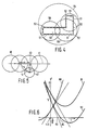
- Figures 2 and 3 a side view and an end view are shown of a cluster of spherical bubbles representing a right cylinder
- the cylinder 1 is shown as a dotted outline, the bubble outlines and lines of intersection being shown as solid lines. Owing to the geometrical simplicity of the object being represented, only two sizes of bubbles are required to achieve the degree of representational precision required in this case.
- the main body of the cylinder 1 is represented by four major interpenetrating spherical bubbles 2, 3, 4 and 5 of equal radius R, their centres 6, 7, 8 and 9 respectively being arranged at regular intervals on a straight line.
- the lines of intersection of these four bubbles appear as straight lines 10, 11 and 12, though these lines are an edge-on view of the circles of intersection of the bubbles.
- the radii of the bubbles and the separation of their centres are chosen so that the circles of intersection lie in the surface of the cylinder, the bubbles projecting beyond the spheres by an amount P.
- the end faces of the cylinder are represented by a ring of eight minor regularly spaced interpenetrating bubbles 13 to 20 inclusive of equal radius r, their centres 21 to 28 inclusive being arranged at regular intervals around a circle, as shown in the end view of Figure 3.
- the end face 29 of the cylinder is contained within the combination of major end bubble 2 and the minor bubbles 13 to 20 inclusive.
- the representation of cylinder 1 consists of the relative positions of the centres of the twenty bubbles of the cluster together with the radius of each bubble.
- the representational precision of the cluster could be improved by reducing the radius of the major bubbles slightly, i.e. reducing P, and using a greater number of major bubbles packed more closely together to represent the cylindrical surface. Greater numbers and a variety of smaller sizes of minor bubbles would be needed to approximate the flat end and sharp edge of the cylinder with increased precision.
- the representation still consists of a list of the relative coordinates of the bubble centres in an appropriate system of axes together with the radius of each bubble.
- the amount of calculation to be done in predicting a collision is proportional to the product of the numbers of bubbles in the two clusters.
- the amount of calculation can be greatly reduced in most practical situations by the use of guard bubbles which enclose a selection of the cluster bubbles and by testing for a collision between guard bubbles of the two clusters first. If no collision between guard bubbles is detected, no reference need be made to the cluster bubbles.
- Figure 4 shows, as an example, an L-shaped body having to levels of guard bubbles.
- the cluster representing the body 50 is composed of twelve major bubbles 51 and six minor bubbles 52, five of which enclose corners of the body and one of which fills in a gap between two major bubbles on the long vertical side of the body.
- a first level of three guard bubbles 53, 55 and 56 are shown which, between them, not only enclose the body but also all the bubbles of the cluster.
- the first level guard bubbles interpenetrate one another to provide the complete enclosure of body and cluster.
- Each first level guard bubble encloses a selection of the bubbles.
- guard bubbles 55 and 56 overlap.
- guard bubble 55 In the region of their overlap, two bubbles 51 overlap, one of these bubbles 51 being completely enclosed by guard bubble 55 and the other bubble 51 being completely enclosed by guard bubble 56. Thus all of the bubbles 51 of a selection are assigned to and completely by only one of the guard bubbles of the next outer level. Finally, a single guard bubble 54 at a second outermost level encloses all three guard bubbles 53, 55 and 56.
- each may be represented by a cluster of bubbles and by a succession of levels of guard bubbles terminating in a single guard bubble enclosing all bubbles.
- the collision prediction calculation is carried out initially on the outermost guard bubbles of the two clusters. If a collision is detected between these guard bubbles only the next level down of guard bubbles needs to be examined. For example, if two Figure 4 objects are in proximity to one another and the outer most guard bubbles indicate collision, only nine calculations have to be carried out since there are only three lower level guard bubbles in each cluster. If the cluster bubbles had been examined there would have been 18 ⁇ 18 or 324 calculations needed. Thus there is considerable benefit in representing the object at lower definition by another set of fewer, larger, bubbles, the guard bubbles. Only when the two objects are close will the cluster bubbles have to be examined for collision.
- Guard bubbles 31 and 33 having centres 30 and 32 respectviely, each enclose one of the rings of eight minor bubbles representing the cylinder end faces. In a collision calculation only these two end guard bubbles 3 and 33 and the four major bubbles 2, 3, 4 and 5 need be interrogated initially, reducing the number of collision calculations by 14 in most cases.
- Figure 5 shows the geometry which exists at the moment of collision between two bubbles, which can either be isolated single bubbles or which can each be a bubble from the two clusters representing the objects.
- a first bubble 40, radius r1 is shown moving along a straight line path 41 relative to a second bubble 42, radius r2. From the known trajectory of bubble 40, the distance of closest approach d of the bubble centres can be calculated. Distance x along the path 41 is measured from the point of closest approach 43 and will be known in advance as a function of time.
- the above calculation is repeated for every pair of bubbles, taken one each from the clusters representing the object, at intervals of time between which a proposed motion is substantially linear. Since the relative positions and radii of all bubbles are known at any time during the proposed relative movement of the clusters, the first collision between a pair of bubbles can be detected in advance of an actual collision occurring between the real objects and appropriate evasive action taken.
- the cylindrical workpiece 61 is represented by a cluster of interpenetrating spherical bubbles, for example the cluster shown in Figures 2 and 3.
- the geometrical outlines of the headstock 62, the tailstock 63, the toolpost 65 and the saddle 66 are each represented by an appropriate cluster of interpenetrating spheres.
- the sets of bubble radii, their relative positions in each cluster together with the positions of the clusters relative to one another and to a coordinate system of the robot manipulator are stored in the real only memory 69. Also stored in ROM 69 are the initial and desired final positions and orientations of the workpiece 61.
- ROM 69 also contains a program for calculating an initial trajectory for the workpiece 61 to pass from its initial to its final position regardless of the positions of the lathe parts.
- ROM 69 also contains a program for dividing the initial trajectory into a sequence of straigth line approximations, or path segments, which are traversed by object 61 at constant velocity. Equation (1) calculation is then carried out at the beginning of each path segment for an overall guard bubble for object 61 in relation to an overall guard bubble for each of the lathe parts. If no collision is indicated, the segment is actually traversed by the object moved by the robot manipulator acting on numerical instructions provided by the calculating means 81. If a collision is indicated, the calculations are repeated for the next lower level of guard bubbles. If no collision is indicated, the segment is traversed, otherwise the next lower level, which may be the defining cluster, are investigated.
- a collision is still indicated between a bubble of the cluster representing the cylinder and a bubble of the cluster representing a lathe part
- the position of the potential collision is recorded and a new path segment calculated lying away from the lathe part in the direction of the line joining the centre of the lathe part bubble with the recorded point of potential collision.
- the collision calculations are then repeated for the new path segment and, in the absence of collision indications, the new path segment is traversed.
- a new trajectory is calculated to reach the final position which new trajectory is divided into linear path segment approximations as before.
- An alternative method of calculating the collision time between two bubbles which avoids the use of the square root operation and which is hence much shorter in computer time, is to use Newton′s approximation to find an approximate solution, and then iterate to find the exact solution to the required accuracy.
- Newton′s approximation will always be a time that is earlier than the real time of collision, if the spheres are going to collide at all. Therefore the computation of the earliest pair of spheres to collide can be done using the approximate solutions rather than the exact solutions. Having found the estimated time of the earliest collision, the process can be repeated to converge on the actual time of collision.
- the coordinates of the enctres of the spheres are (a*t+d,b*t+e,c*t+f) and (g*t+j,h*t+k,i*t+l), their radii are r1 and r2, offset is a value which if it is greater than zero allows for small departures from linear motion, and t is the predicted time of collision.
- This function does not compute the exact time of collision, but a time which is guaranteed to be just before the actual time of collision. To find out when the representations of two solid bodies would collide, this function is applied to all possible pairs of spheres, one in each body, and the minimum value of t is found. To find the exact time of collision, the equations of motion are re-computed and the process is repeated to find a better estimate of the collision time. Successive iterations normally converge rapidly on the required collision time.
Landscapes
- Engineering & Computer Science (AREA)
- Robotics (AREA)
- Mechanical Engineering (AREA)
- Control Of Position, Course, Altitude, Or Attitude Of Moving Bodies (AREA)
- Management, Administration, Business Operations System, And Electronic Commerce (AREA)
- Numerical Control (AREA)
- Manipulator (AREA)
- Image Generation (AREA)
- Image Analysis (AREA)
Applications Claiming Priority (2)
| Application Number | Priority Date | Filing Date | Title |
|---|---|---|---|
| GB08625835A GB2196763A (en) | 1986-10-29 | 1986-10-29 | Solid modeling |
| GB8625835 | 1986-10-29 |
Publications (2)
| Publication Number | Publication Date |
|---|---|
| EP0268317A2 true EP0268317A2 (de) | 1988-05-25 |
| EP0268317A3 EP0268317A3 (de) | 1990-01-10 |
Family
ID=10606471
Family Applications (1)
| Application Number | Title | Priority Date | Filing Date |
|---|---|---|---|
| EP87202065A Ceased EP0268317A3 (de) | 1986-10-29 | 1987-10-27 | Verfahren und Einrichtung zur Steuerung der Bahn eines geleiteten Organs |
Country Status (3)
| Country | Link |
|---|---|
| EP (1) | EP0268317A3 (de) |
| JP (1) | JP2537909B2 (de) |
| GB (1) | GB2196763A (de) |
Cited By (8)
| Publication number | Priority date | Publication date | Assignee | Title |
|---|---|---|---|---|
| GB2227106A (en) * | 1988-11-12 | 1990-07-18 | Toyoda Chuo Kenkyusho Kk | Detecting collision |
| EP0412619A3 (en) * | 1989-08-11 | 1991-05-29 | N.V. Philips' Gloeilampenfabrieken | Method and apparatus for determining potential collisions using a swept bubble data hierarchy |
| US5056031A (en) * | 1988-11-12 | 1991-10-08 | Kabushiki Kaisha Toyota Chuo Kenyusho | Apparatus for detecting the collision of moving objects |
| EP0426249A3 (en) * | 1989-11-01 | 1992-03-18 | N.V. Philips' Gloeilampenfabrieken | Method and apparatus for controlling robots and the like using a bubble data hierarchy placed along a medial axis |
| EP0753837A3 (de) * | 1995-07-11 | 1998-01-07 | Fujitsu Limited | Verfahren zur Interferenz-Überwachung |
| EP1672450A1 (de) * | 2004-12-20 | 2006-06-21 | Dr. Johannes Heidenhain GmbH | Verfahren zur Ermittlung einer möglichen Kollision mindestens zweier zueinander beweglicher Objekte |
| US10759056B2 (en) | 2017-07-31 | 2020-09-01 | Fanuc Corporation | Control unit for articulated robot |
| CN120802731A (zh) * | 2025-07-03 | 2025-10-17 | 北京星元智信科技有限公司 | 一种智能工业的优化控制方法及系统 |
Families Citing this family (8)
| Publication number | Priority date | Publication date | Assignee | Title |
|---|---|---|---|---|
| JP2895856B2 (ja) * | 1989-05-19 | 1999-05-24 | 三洋電機株式会社 | 多面体間の面接触判別装置 |
| JPH02311296A (ja) * | 1989-05-23 | 1990-12-26 | Daikin Ind Ltd | 産業用ロボット制御方法およびその装置 |
| JP4569390B2 (ja) * | 2005-06-02 | 2010-10-27 | トヨタ自動車株式会社 | 物体間衝突判定装置及び方法 |
| US8676379B2 (en) * | 2006-07-04 | 2014-03-18 | Panasonic Corporation | Device and method for controlling robot arm, robot, and robot arm control program |
| JP5250858B2 (ja) * | 2007-05-08 | 2013-07-31 | 株式会社Ihi | 複数ロボットの衝突検知方法及びロボット装置 |
| JP5553373B2 (ja) * | 2008-03-25 | 2014-07-16 | 株式会社Ihi | ロボット装置の制御方法及びロボット装置 |
| KR102379623B1 (ko) * | 2014-02-05 | 2022-03-29 | 인튜어티브 서지컬 오퍼레이션즈 인코포레이티드 | 동적 가상 충돌 객체를 위한 시스템 및 방법 |
| WO2020066949A1 (ja) * | 2018-09-26 | 2020-04-02 | 日本電産株式会社 | ロボットの経路決定装置、ロボットの経路決定方法、プログラム |
Family Cites Families (4)
| Publication number | Priority date | Publication date | Assignee | Title |
|---|---|---|---|---|
| JPS57113111A (en) * | 1980-12-30 | 1982-07-14 | Fanuc Ltd | Robot control system |
| SE456048B (sv) * | 1982-02-24 | 1988-08-29 | Philips Norden Ab | Sett och anordning for att bestemma kollisionsrisken for tva inbordes rorliga kroppar |
| JPH0619657B2 (ja) * | 1983-12-09 | 1994-03-16 | 株式会社日立製作所 | ロボツトの制御方法および装置 |
| DE3401060A1 (de) * | 1984-01-13 | 1986-01-23 | Dr. Johannes Heidenhain Gmbh, 8225 Traunreut | Verfahren zum grafischen darstellen eines gebildes |
-
1986
- 1986-10-29 GB GB08625835A patent/GB2196763A/en not_active Withdrawn
-
1987
- 1987-10-27 EP EP87202065A patent/EP0268317A3/de not_active Ceased
- 1987-10-29 JP JP62271955A patent/JP2537909B2/ja not_active Expired - Lifetime
Cited By (13)
| Publication number | Priority date | Publication date | Assignee | Title |
|---|---|---|---|---|
| GB2227106A (en) * | 1988-11-12 | 1990-07-18 | Toyoda Chuo Kenkyusho Kk | Detecting collision |
| US5056031A (en) * | 1988-11-12 | 1991-10-08 | Kabushiki Kaisha Toyota Chuo Kenyusho | Apparatus for detecting the collision of moving objects |
| GB2227106B (en) * | 1988-11-12 | 1993-05-19 | Toyoda Chuo Kenkyusho Kk | Apparatus for detecting the collision of moving objects |
| EP0412619A3 (en) * | 1989-08-11 | 1991-05-29 | N.V. Philips' Gloeilampenfabrieken | Method and apparatus for determining potential collisions using a swept bubble data hierarchy |
| EP0426249A3 (en) * | 1989-11-01 | 1992-03-18 | N.V. Philips' Gloeilampenfabrieken | Method and apparatus for controlling robots and the like using a bubble data hierarchy placed along a medial axis |
| US5943056A (en) * | 1995-07-11 | 1999-08-24 | Fujitsu Ltd. | Interference checking method |
| EP0753837A3 (de) * | 1995-07-11 | 1998-01-07 | Fujitsu Limited | Verfahren zur Interferenz-Überwachung |
| EP1241628A3 (de) * | 1995-07-11 | 2004-08-18 | Fujitsu Limited | Verfahren zur Interferenz-Überwachung |
| EP1672450A1 (de) * | 2004-12-20 | 2006-06-21 | Dr. Johannes Heidenhain GmbH | Verfahren zur Ermittlung einer möglichen Kollision mindestens zweier zueinander beweglicher Objekte |
| US7227328B2 (en) | 2004-12-20 | 2007-06-05 | Dr. Johannes Heidenhain Gmbh | Method for detecting a possible collision of at least two objects moving with respect to each other |
| US10759056B2 (en) | 2017-07-31 | 2020-09-01 | Fanuc Corporation | Control unit for articulated robot |
| CN120802731A (zh) * | 2025-07-03 | 2025-10-17 | 北京星元智信科技有限公司 | 一种智能工业的优化控制方法及系统 |
| CN120802731B (zh) * | 2025-07-03 | 2026-01-02 | 北京星元智信科技有限公司 | 一种智能工业的优化控制方法及系统 |
Also Published As
| Publication number | Publication date |
|---|---|
| GB8625835D0 (en) | 1986-12-03 |
| JPS63158620A (ja) | 1988-07-01 |
| JP2537909B2 (ja) | 1996-09-25 |
| GB2196763A (en) | 1988-05-05 |
| EP0268317A3 (de) | 1990-01-10 |
Similar Documents
| Publication | Publication Date | Title |
|---|---|---|
| US4922430A (en) | Method and apparatus for controlling the movement of a guided object | |
| EP0268317A2 (de) | Verfahren und Einrichtung zur Steuerung der Bahn eines geleiteten Organs | |
| CA2120534C (en) | Real time collision detection | |
| Janabi-Sharifi et al. | Automatic selection of image features for visual servoing | |
| EP0307091B1 (de) | Gegenstandskollisionserkennungsschaltung | |
| EP0426249B1 (de) | Verfahren und Vorrichtung zur Steuerung von Robotern und ähnlichem zum Gebrauch hierarchisch organisierter "Bubble-Daten", die entlang einer Mittelachse angeordnet sind | |
| Mason | Manipulator grasping and pushing operations | |
| Bedi et al. | Advanced interpolation techniques for NC machines | |
| EP1901150B1 (de) | Verfahren und Vorrichtung zur Vermeidung von Kollisionen zwischen einem Industrieroboter und einem Objekt | |
| Ahuja et al. | Interference Detection and Collision Avoidance Among Three Dimensional Objects. | |
| Bobrow | A direct minimization approach for obtaining the distance between convex polyhedra | |
| US6862026B2 (en) | Process and device for collision detection of objects | |
| Elber | Freeform surface region optimization for 3-axis and 5-axis milling | |
| McKerrow | Echolocation—from range to outline segments | |
| Rubio et al. | Calculation of tool paths for a torus mill on free-form surfaces on five-axis machines with detection and elimination of interference | |
| Beaufrere et al. | A mobile robot navigation method using a fuzzy logic approach | |
| EP0276312A1 (de) | Verfahren zur berechnung eines normalvektors | |
| Hayward et al. | Efficient collision prediction among many moving objects | |
| Castore | Solid modeling, aspect graphs, and robot vision | |
| Xiao et al. | Toward obtaining all possible contacts-growing a polyhedron by its location uncertainty | |
| Liu et al. | Distance calculations in motion planning problems with interference situations | |
| Vasseur et al. | Navigation of car-like mobile robots in obstructed environments using convex polygonal cells | |
| Pretlove et al. | The surrey attentive robot vision system | |
| Liu et al. | A new solid model HSM and its application to interference detection between moving objects | |
| Seiler et al. | Tool interference detection and avoidance based on offset nets |
Legal Events
| Date | Code | Title | Description |
|---|---|---|---|
| PUAI | Public reference made under article 153(3) epc to a published international application that has entered the european phase |
Free format text: ORIGINAL CODE: 0009012 |
|
| AK | Designated contracting states |
Kind code of ref document: A2 Designated state(s): DE FR GB SE |
|
| RAP3 | Party data changed (applicant data changed or rights of an application transferred) |
Owner name: N.V. PHILIPS' GLOEILAMPENFABRIEKEN Owner name: PHILIPS ELECTRONIC AND ASSOCIATED INDUSTRIES LIMIT |
|
| PUAL | Search report despatched |
Free format text: ORIGINAL CODE: 0009013 |
|
| AK | Designated contracting states |
Kind code of ref document: A3 Designated state(s): DE FR GB SE |
|
| 17P | Request for examination filed |
Effective date: 19900626 |
|
| 17Q | First examination report despatched |
Effective date: 19920207 |
|
| RAP3 | Party data changed (applicant data changed or rights of an application transferred) |
Owner name: N.V. PHILIPS' GLOEILAMPENFABRIEKEN Owner name: PHILIPS ELECTRONICS UK LIMITED |
|
| STAA | Information on the status of an ep patent application or granted ep patent |
Free format text: STATUS: THE APPLICATION HAS BEEN REFUSED |
|
| 18R | Application refused |
Effective date: 19930327 |
|
| RIN1 | Information on inventor provided before grant (corrected) |
Inventor name: WAVISH, PETER ROY |