EP0268024A1 - Dispositif de protection contre les surtensions pour conducteurs de télécommunications - Google Patents
Dispositif de protection contre les surtensions pour conducteurs de télécommunications Download PDFInfo
- Publication number
- EP0268024A1 EP0268024A1 EP87112025A EP87112025A EP0268024A1 EP 0268024 A1 EP0268024 A1 EP 0268024A1 EP 87112025 A EP87112025 A EP 87112025A EP 87112025 A EP87112025 A EP 87112025A EP 0268024 A1 EP0268024 A1 EP 0268024A1
- Authority
- EP
- European Patent Office
- Prior art keywords
- contact
- circuit board
- protection device
- earth
- earth conductor
- Prior art date
- Legal status (The legal status is an assumption and is not a legal conclusion. Google has not performed a legal analysis and makes no representation as to the accuracy of the status listed.)
- Granted
Links
- 239000004020 conductor Substances 0.000 title claims abstract description 30
- 238000005516 engineering process Methods 0.000 claims description 3
- 241001061269 Lestes Species 0.000 claims 1
- 238000000926 separation method Methods 0.000 description 3
- 238000006073 displacement reaction Methods 0.000 description 2
- 238000009413 insulation Methods 0.000 description 2
- 238000005452 bending Methods 0.000 description 1
- 238000009434 installation Methods 0.000 description 1
- 230000001012 protector Effects 0.000 description 1
- 229910000679 solder Inorganic materials 0.000 description 1
Images
Classifications
-
- H—ELECTRICITY
- H01—ELECTRIC ELEMENTS
- H01T—SPARK GAPS; OVERVOLTAGE ARRESTERS USING SPARK GAPS; SPARKING PLUGS; CORONA DEVICES; GENERATING IONS TO BE INTRODUCED INTO NON-ENCLOSED GASES
- H01T4/00—Overvoltage arresters using spark gaps
- H01T4/06—Mounting arrangements for a plurality of overvoltage arresters
-
- H—ELECTRICITY
- H05—ELECTRIC TECHNIQUES NOT OTHERWISE PROVIDED FOR
- H05K—PRINTED CIRCUITS; CASINGS OR CONSTRUCTIONAL DETAILS OF ELECTRIC APPARATUS; MANUFACTURE OF ASSEMBLAGES OF ELECTRICAL COMPONENTS
- H05K1/00—Printed circuits
- H05K1/02—Details
- H05K1/0213—Electrical arrangements not otherwise provided for
- H05K1/0254—High voltage adaptations; Electrical insulation details; Overvoltage or electrostatic discharge protection ; Arrangements for regulating voltages or for using plural voltages
-
- H—ELECTRICITY
- H05—ELECTRIC TECHNIQUES NOT OTHERWISE PROVIDED FOR
- H05K—PRINTED CIRCUITS; CASINGS OR CONSTRUCTIONAL DETAILS OF ELECTRIC APPARATUS; MANUFACTURE OF ASSEMBLAGES OF ELECTRICAL COMPONENTS
- H05K1/00—Printed circuits
- H05K1/02—Details
- H05K1/11—Printed elements for providing electric connections to or between printed circuits
- H05K1/117—Pads along the edge of rigid circuit boards, e.g. for pluggable connectors
Definitions
- the invention relates to an overvoltage protection device, in particular for cable wires in telecommunications technology, with a plurality of contact blades which can be inserted between isolating contact tabs of an isolating strip and with an earth conductor.
- a surge arrester of this type is known.
- This surge arrester device is preferably used for isolating strips in telecommunications technology.
- the surge arrester device is inserted into the isolating strip from above.
- the surge arrester device has a downwardly projecting contact blade for each incoming and outgoing cable wire, which is inserted between the isolating contact tabs.
- the contact blades are extended upwards so far that they contact a pole of a surge arrester in the housing of the surge arrester device.
- the other pole of the surge arrester is connected to an earth rail.
- the overvoltage lying on the cable wire flows via a insulation displacement contact, the isolating contact and the contact blade to one pole of the surge arrester.
- the overvoltage bridges the spark gap of the surge arrester filled with gas and is diverted to the earth rail.
- the damaged arrester In the event of an overvoltage, the damaged arrester must be replaced.
- a disadvantage of this surge arrester device is that an surge arrester is necessary for each incoming and outgoing cable wire. With a isolating strip with ten double wires, this means that twenty arresters are necessary.
- the housing of the surge arrester device requires several individual chambers for receiving and storing the arresters.
- the object of the invention is therefore to create an overvoltage protection device of the generic type which has as few components as possible.
- the earth conductor is arranged at a defined distance from the contact blades inserted between the separating contact lugs, so that a coarse spark gap is formed. This means that in the event of an overvoltage, the overvoltage that occurs "jumps" from the contact knife to the earth conductor and is discharged via the earth conductor.
- the installation of expensive surge arresters in a housing is therefore no longer necessary since the device consists of only two components, namely the contact blades and the earth conductor.
- the contact knives are designed as conductor tracks which are printed on both sides of a printed circuit board.
- the earth conductor consists of a metallic, electrically conductive strip, which is semicircular in cross section. One end of the conductor track is inserted between the isolating contact tabs on the isolating strip. The other end of the conductor track extends below the semi-circular bar. This ensures that the conductor tracks to the earth conductor are given a defined distance that forms the rough function path.
- the conductor tracks lying opposite one another on the printed circuit board are not connected to one another. The earth conductor therefore consists of two semicircular strips on both sides of the circuit board. This embodiment is used when an electrical separation between the incoming and outgoing cable wires is desired, while at the same time protecting against overvoltage.
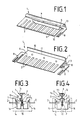
- the overvoltage protection device 1 - as shown in FIGS. 1 to 3 - consists of a printed circuit board 6 and an earth conductor 4.
- two adjacent conductor tracks forming the contact blades 3 are printed on both sides.
- two contact knives 3 located opposite one another on both sides are connected to one another by a through-connection 9.
- the contact knives 3 arranged side by side run parallel to the narrow sides 10 of the printed circuit board 6.
- the contact blades 3 do not extend over the entire width of the circuit board 6, but already end after about 2/3 of the width of the circuit board 6.
- the earth conductor 4 On the free third of the circuit board 6 is on one side of the circuit board 6 via a screw, solder or clamp connection arranged the earth conductor 4, which is designed as a semi-circular cross-section bar 5. Between the free edge area of the semicircular strip 5 of the earth strip 4 and the contact blades 3, which end under the semicircular strip 5, there is thus a defined distance 7 forming a coarse spark gap.
- the other end of the earth conductor 4 is about 90 ° over its long side the long side 11 of the circuit board 6 is bent toward the other side of the circuit board and projects so far that a drawing edge 12 is formed.
- a further semicircular bar 13 corresponding to the cross section of the semicircular bar 5 is thus provided.
- This semicircular strip 13 and the pulling edge 12 make it easier to pull out the overvoltage protection device 1 (FIG. 3) which is inserted into a separating strip 14.
- a fork-shaped earth contact 8 is arranged on the earth conductor 4 on the narrow sides 10 of the printed circuit board 6. This first embodiment of the overvoltage protection device 11 is used if, when the overvoltage protection device 1 is plugged into the isolating strip 14 (to simultaneously protect against overvoltages), there should be no separation between the incoming and outgoing cable core 2.
- FIG. 4 shows a second embodiment of an overvoltage protection device 1a which is inserted into the isolating strip 14 if, with simultaneous protection against overvoltages, a separation between the incoming and the outgoing cable core 2 is desired.
- This second embodiment differs from the first in that the two contact knives 3 located opposite one another on both sides of the printed circuit board 6 are not electrically connected to one another and in that the earth conductor 4a consists of two semicircular strips 5 which are arranged on both sides of the printed circuit board 6 and in one piece are trained.
- the overvoltage passes from the cable core 2 via the insulation displacement contact 16 and the isolating contact 15 to the contact knife 3, from where the overvoltage jumps to the earth conductor 4, 4 a.
- the earth conductor 4, 4 a is connected to an earth connection, not shown, via the fork-shaped earth contacts 8.
- the overvoltage lying on the incoming or outgoing cable wire 2 always reaches the semicircular strip 5 arranged on one side of the circuit board 6, since the two opposing contact blades 3 are connected to one another.
- the two opposing contact blades 3 are electrically separated from one another, so that here the overvoltage jumps onto the earth conductor 4 a either on one or the other side of the circuit board 6, depending on whether the overvoltage on the incoming or outgoing cable core 2 is present.
Landscapes
- Emergency Protection Circuit Devices (AREA)
- Medicines Containing Material From Animals Or Micro-Organisms (AREA)
- Saccharide Compounds (AREA)
- Details Of Connecting Devices For Male And Female Coupling (AREA)
- Structure Of Telephone Exchanges (AREA)
Priority Applications (1)
| Application Number | Priority Date | Filing Date | Title |
|---|---|---|---|
| AT87112025T ATE50890T1 (de) | 1986-10-25 | 1987-08-19 | Ueberspannungsschutzvorrichtung fuer kabeladern der fernmeldetechnik. |
Applications Claiming Priority (2)
| Application Number | Priority Date | Filing Date | Title |
|---|---|---|---|
| DE3636695 | 1986-10-25 | ||
| DE3636695A DE3636695C1 (de) | 1986-10-25 | 1986-10-25 | UEberspannungsschutzvorrichtung fuer Kabeladern der Fernmeldetechnik |
Publications (2)
| Publication Number | Publication Date |
|---|---|
| EP0268024A1 true EP0268024A1 (fr) | 1988-05-25 |
| EP0268024B1 EP0268024B1 (fr) | 1990-03-07 |
Family
ID=6312670
Family Applications (1)
| Application Number | Title | Priority Date | Filing Date |
|---|---|---|---|
| EP87112025A Expired - Lifetime EP0268024B1 (fr) | 1986-10-25 | 1987-08-19 | Dispositif de protection contre les surtensions pour conducteurs de télécommunications |
Country Status (6)
| Country | Link |
|---|---|
| EP (1) | EP0268024B1 (fr) |
| AT (1) | ATE50890T1 (fr) |
| DE (2) | DE3636695C1 (fr) |
| ES (1) | ES2015291B3 (fr) |
| FI (1) | FI84949C (fr) |
| GR (1) | GR3000371T3 (fr) |
Families Citing this family (1)
| Publication number | Priority date | Publication date | Assignee | Title |
|---|---|---|---|---|
| DE3843524A1 (de) * | 1988-04-23 | 1990-06-28 | Dehn & Soehne | Anordnung zum wahlweisen verbinden elektrischer leitungen |
Citations (4)
| Publication number | Priority date | Publication date | Assignee | Title |
|---|---|---|---|---|
| DE1112574B (de) * | 1958-12-15 | 1961-08-10 | Licentia Gmbh | UEberspannungsschutz fuer Elektrizitaetszaehler |
| DE1249935B (fr) * | 1962-07-24 | 1967-09-14 | ||
| US3992652A (en) * | 1974-09-09 | 1976-11-16 | Gte Sylvania Incorporated | Bulk electrical surge arrester |
| EP0038412A1 (fr) * | 1980-04-17 | 1981-10-28 | KRONE GmbH | Dispositif parafoudre pour ensemble de connecteurs de téléphonie |
Family Cites Families (1)
| Publication number | Priority date | Publication date | Assignee | Title |
|---|---|---|---|---|
| DE890382C (de) * | 1951-08-12 | 1953-09-17 | Quante & Co K G | Grobschutz-Spannungsableiter |
-
1986
- 1986-10-25 DE DE3636695A patent/DE3636695C1/de not_active Expired
-
1987
- 1987-08-19 EP EP87112025A patent/EP0268024B1/fr not_active Expired - Lifetime
- 1987-08-19 AT AT87112025T patent/ATE50890T1/de active
- 1987-08-19 DE DE8787112025T patent/DE3761866D1/de not_active Expired - Lifetime
- 1987-08-19 ES ES87112025T patent/ES2015291B3/es not_active Expired - Lifetime
- 1987-10-23 FI FI874681A patent/FI84949C/fi not_active IP Right Cessation
-
1990
- 1990-03-08 GR GR90400082T patent/GR3000371T3/el unknown
Patent Citations (4)
| Publication number | Priority date | Publication date | Assignee | Title |
|---|---|---|---|---|
| DE1112574B (de) * | 1958-12-15 | 1961-08-10 | Licentia Gmbh | UEberspannungsschutz fuer Elektrizitaetszaehler |
| DE1249935B (fr) * | 1962-07-24 | 1967-09-14 | ||
| US3992652A (en) * | 1974-09-09 | 1976-11-16 | Gte Sylvania Incorporated | Bulk electrical surge arrester |
| EP0038412A1 (fr) * | 1980-04-17 | 1981-10-28 | KRONE GmbH | Dispositif parafoudre pour ensemble de connecteurs de téléphonie |
Also Published As
| Publication number | Publication date |
|---|---|
| GR3000371T3 (en) | 1991-06-07 |
| FI874681L (fi) | 1988-04-26 |
| DE3761866D1 (de) | 1990-04-12 |
| FI84949C (fi) | 1992-02-10 |
| ATE50890T1 (de) | 1990-03-15 |
| ES2015291B3 (es) | 1990-08-16 |
| DE3636695C1 (de) | 1988-03-24 |
| EP0268024B1 (fr) | 1990-03-07 |
| FI874681A0 (fi) | 1987-10-23 |
| FI84949B (fi) | 1991-10-31 |
Similar Documents
| Publication | Publication Date | Title |
|---|---|---|
| DE3687321T2 (de) | Modulares verteilergestell mit schutzmoduln, die durch auftrennung des stromkreises getestet werden koennen. | |
| DE3909783C2 (de) | Schutzstecker für Anschlußleisten der Fernmelde- und Datentechnik | |
| EP1658660B1 (fr) | Module de raccordement de distribution | |
| EP0446572A1 (fr) | Bloc de connexion pour technique des télécommunications et de l'informatique | |
| DE3509523C2 (de) | Kabelabschlußeinheit | |
| DE3917270A1 (de) | Anschlussleiste mit ueberspannungsschutz | |
| DE3137429A1 (de) | Vorrichtung zur herstellung eines loet,- schraub- undabisolierfreien einfach- oder mehrfachkontaktes an einem anschlusselement | |
| DE2706681A1 (de) | Schutzeinrichtung fuer niederspannungsleitungen, insbesondere fuer fernsprechnetze | |
| EP1614200B1 (fr) | Magasin de protection contre les surtensions pour un systeme de telecommunication | |
| EP2044781A1 (fr) | Bloc de connexion | |
| EP0338187A2 (fr) | Fiche de protection pour boîters d'interuption ou de disjonction | |
| EP2044654B1 (fr) | Bloc de connexion | |
| DE102005042163B3 (de) | Schutzstecker für ein Anschlussmodul | |
| DE3422607C2 (fr) | ||
| DE2617172C3 (de) | Anschlußblock für Kabelenden, insbesondere für Fernmeldekabel | |
| EP0990280B1 (fr) | Connecteur de protection pour dispositif utilise dans la technique des telecommunications | |
| EP0268024B1 (fr) | Dispositif de protection contre les surtensions pour conducteurs de télécommunications | |
| DE2720220A1 (de) | Sicherungsleiste zur halterung elektrischer sicherungen | |
| DE2621101C3 (de) | Überspannungsableitervorrichtung für Kabelabschlußgeräte der Fernmeldelinientechnik | |
| EP1059703B1 (fr) | Fiche de protection pour un dispositif de la technique de télécommunication | |
| DD297286A5 (de) | Schutzeinrichtung fuer einen verteiler in einer telekommunikationsanlage | |
| DE19818477A1 (de) | Überspannungsschutzmagazin für eine Einrichtung der Telekommunikationstechnik | |
| DE3218160C2 (de) | Vorrichtung zum Schutz von Fernmeldeanlagen gegen Überspannungen | |
| EP1894281B1 (fr) | Fiche de protection pour dispositifs de distribution de telecommunication et de transmission de donnees | |
| DE19822958A1 (de) | Elektrische Anschlußbaueinheit |
Legal Events
| Date | Code | Title | Description |
|---|---|---|---|
| PUAI | Public reference made under article 153(3) epc to a published international application that has entered the european phase |
Free format text: ORIGINAL CODE: 0009012 |
|
| AK | Designated contracting states |
Kind code of ref document: A1 Designated state(s): AT BE CH DE ES FR GB GR IT LI LU NL SE |
|
| 17P | Request for examination filed |
Effective date: 19880420 |
|
| 17Q | First examination report despatched |
Effective date: 19890609 |
|
| GRAA | (expected) grant |
Free format text: ORIGINAL CODE: 0009210 |
|
| AK | Designated contracting states |
Kind code of ref document: B1 Designated state(s): AT BE CH DE ES FR GB GR IT LI LU NL SE |
|
| REF | Corresponds to: |
Ref document number: 50890 Country of ref document: AT Date of ref document: 19900315 Kind code of ref document: T |
|
| ITF | It: translation for a ep patent filed | ||
| ET | Fr: translation filed | ||
| GBT | Gb: translation of ep patent filed (gb section 77(6)(a)/1977) | ||
| REF | Corresponds to: |
Ref document number: 3761866 Country of ref document: DE Date of ref document: 19900412 |
|
| REG | Reference to a national code |
Ref country code: GR Ref legal event code: FG4A Free format text: 3000371 |
|
| PLBE | No opposition filed within time limit |
Free format text: ORIGINAL CODE: 0009261 |
|
| STAA | Information on the status of an ep patent application or granted ep patent |
Free format text: STATUS: NO OPPOSITION FILED WITHIN TIME LIMIT |
|
| 26N | No opposition filed | ||
| ITTA | It: last paid annual fee | ||
| PGFP | Annual fee paid to national office [announced via postgrant information from national office to epo] |
Ref country code: GB Payment date: 19930709 Year of fee payment: 7 |
|
| PGFP | Annual fee paid to national office [announced via postgrant information from national office to epo] |
Ref country code: DE Payment date: 19930814 Year of fee payment: 7 |
|
| PGFP | Annual fee paid to national office [announced via postgrant information from national office to epo] |
Ref country code: FR Payment date: 19930818 Year of fee payment: 7 |
|
| PGFP | Annual fee paid to national office [announced via postgrant information from national office to epo] |
Ref country code: SE Payment date: 19930826 Year of fee payment: 7 Ref country code: AT Payment date: 19930826 Year of fee payment: 7 |
|
| PGFP | Annual fee paid to national office [announced via postgrant information from national office to epo] |
Ref country code: LU Payment date: 19930827 Year of fee payment: 7 |
|
| PGFP | Annual fee paid to national office [announced via postgrant information from national office to epo] |
Ref country code: ES Payment date: 19930830 Year of fee payment: 7 Ref country code: BE Payment date: 19930830 Year of fee payment: 7 |
|
| PGFP | Annual fee paid to national office [announced via postgrant information from national office to epo] |
Ref country code: NL Payment date: 19930831 Year of fee payment: 7 Ref country code: GR Payment date: 19930831 Year of fee payment: 7 |
|
| PGFP | Annual fee paid to national office [announced via postgrant information from national office to epo] |
Ref country code: CH Payment date: 19930920 Year of fee payment: 7 |
|
| EPTA | Lu: last paid annual fee | ||
| PG25 | Lapsed in a contracting state [announced via postgrant information from national office to epo] |
Ref country code: LU Free format text: LAPSE BECAUSE OF NON-PAYMENT OF DUE FEES Effective date: 19940819 Ref country code: GB Effective date: 19940819 Ref country code: AT Effective date: 19940819 |
|
| PG25 | Lapsed in a contracting state [announced via postgrant information from national office to epo] |
Ref country code: SE Effective date: 19940820 Ref country code: ES Free format text: LAPSE BECAUSE OF THE APPLICANT RENOUNCES Effective date: 19940820 |
|
| PG25 | Lapsed in a contracting state [announced via postgrant information from national office to epo] |
Ref country code: LI Effective date: 19940831 Ref country code: CH Effective date: 19940831 Ref country code: BE Effective date: 19940831 |
|
| EAL | Se: european patent in force in sweden |
Ref document number: 87112025.9 |
|
| BERE | Be: lapsed |
Owner name: KRONE A.G. Effective date: 19940831 |
|
| PG25 | Lapsed in a contracting state [announced via postgrant information from national office to epo] |
Ref country code: GR Free format text: THE PATENT HAS BEEN ANNULLED BY A DECISION OF A NATIONAL AUTHORITY Effective date: 19950228 |
|
| PG25 | Lapsed in a contracting state [announced via postgrant information from national office to epo] |
Ref country code: NL Effective date: 19950301 |
|
| NLV4 | Nl: lapsed or anulled due to non-payment of the annual fee | ||
| GBPC | Gb: european patent ceased through non-payment of renewal fee |
Effective date: 19940819 |
|
| PG25 | Lapsed in a contracting state [announced via postgrant information from national office to epo] |
Ref country code: FR Effective date: 19950428 |
|
| REG | Reference to a national code |
Ref country code: CH Ref legal event code: PL Ref country code: GR Ref legal event code: MM2A Free format text: 3000371 |
|
| PG25 | Lapsed in a contracting state [announced via postgrant information from national office to epo] |
Ref country code: DE Effective date: 19950503 |
|
| EUG | Se: european patent has lapsed |
Ref document number: 87112025.9 |
|
| REG | Reference to a national code |
Ref country code: FR Ref legal event code: ST |
|
| REG | Reference to a national code |
Ref country code: ES Ref legal event code: FD2A Effective date: 19991007 |
|
| PG25 | Lapsed in a contracting state [announced via postgrant information from national office to epo] |
Ref country code: IT Free format text: LAPSE BECAUSE OF NON-PAYMENT OF DUE FEES;WARNING: LAPSES OF ITALIAN PATENTS WITH EFFECTIVE DATE BEFORE 2007 MAY HAVE OCCURRED AT ANY TIME BEFORE 2007. THE CORRECT EFFECTIVE DATE MAY BE DIFFERENT FROM THE ONE RECORDED. Effective date: 20050819 |