EP0266761A2 - Messung der Durchflussgeschwindigkeit von Pulver aus einem Fülltrichter - Google Patents
Messung der Durchflussgeschwindigkeit von Pulver aus einem Fülltrichter Download PDFInfo
- Publication number
- EP0266761A2 EP0266761A2 EP87116259A EP87116259A EP0266761A2 EP 0266761 A2 EP0266761 A2 EP 0266761A2 EP 87116259 A EP87116259 A EP 87116259A EP 87116259 A EP87116259 A EP 87116259A EP 0266761 A2 EP0266761 A2 EP 0266761A2
- Authority
- EP
- European Patent Office
- Prior art keywords
- signal
- deadband
- time constant
- absolute value
- filter
- Prior art date
- Legal status (The legal status is an assumption and is not a legal conclusion. Google has not performed a legal analysis and makes no representation as to the accuracy of the status listed.)
- Granted
Links
Images


Classifications
-
- G—PHYSICS
- G01—MEASURING; TESTING
- G01G—WEIGHING
- G01G11/00—Apparatus for weighing a continuous stream of material during flow; Conveyor belt weighers
- G01G11/04—Apparatus for weighing a continuous stream of material during flow; Conveyor belt weighers having electrical weight-sensitive devices
- G01G11/043—Apparatus for weighing a continuous stream of material during flow; Conveyor belt weighers having electrical weight-sensitive devices combined with totalising or integrating devices
-
- G—PHYSICS
- G01—MEASURING; TESTING
- G01G—WEIGHING
- G01G11/00—Apparatus for weighing a continuous stream of material during flow; Conveyor belt weighers
- G01G11/003—Details; specially adapted accessories
Definitions
- the present invention relates to a system and method for measuring the rate at which powdered material flows from a hopper.
- U.S. Patent 4,561,808 discloses a powder feeding system for a thermal spray gun which provides uniform control of powder feed rate. While this device controls the rate of feed through the feed tube, it is also desirable to measure the feed rate from the hopper itself to give an instantaneous indication of either too high or too low a feed rate which would materially affect the quality of a coating when the hopper is used to supply thermal spraying material.
- powdered materials are fed into a heat source.
- the rate at which the powders are fed is a critical process parameter.
- Prior to the present invention there was no suitable means for determining powder flow rate while a part was being sprayed.
- Other commercially available devices were either too slow to respond or could not be calibrated in engineering units for all materials and were too costly.
- the commercially available devices use weight loss over a fixed time period to produce a measurement of the flow rate of material from a hopper. This however results in jitter in the display of feed rate due to noisy amplifiers and inadequate filtering when the selected time period is too short, or too slow a response to transients when longer time intervals are selected.
- the main object of the present invention is to provide a fast response to transients in the feed rate of powdered material from a hopper or other container and to eliminate the disadvantages of prior art techniques.
- a system for measuring the rate at which powdered material flows from a container comprises means for providing a first analog signal representing the weight of a container from which powdered material flows, means for differentiating the analog signal to obtain a second analog signal corresponding to the flow rate, and adaptive filtering means for the second signal which includes a first low pass filter having a first time constant and receptive of the second signal for producing a third signal, and further includes a second low pass filter means in series with the first filter to produce a fourth signal.
- the second filter has a variable time constant and is responsive to a control signal for varying the time constant between a minimum which is equal to the time constant of the first filter and a maximum which is a preselected multiple of the time constant of the first filter.
- the adaptive filtering means also includes means receptive of the third and fourth signals from the two filters for producing the control signal.
- the receptive means comprises comparator means for comparing the absolute value of the difference between the voltage amplitudes of the third and fourth signals to a preselected deadband voltage, and means for varying the control signal to effect the maximum time constant in the second filter when the absolute value of the difference is less than the deadband and to effect a minimum time constant when the absolute value of the difference is greater than the deadband.
- the means for producing the control signal preferably comprises deadband selecting means receptive of the third signal for producing one of a preselected group of deadband reference signals, preferably three signals, one of which is selected in dependence on the amplitude of the output of the first filter.
- the comparator means for comparing compares the selected deadband reference signal to the absolute value of the difference between the third and fourth signals and produces an output control signal corresponding to the comparison.
- the output signal of the comparator means is used for varying the control signal by means of a pulse width modulating means which is receptive of the output signal of the comparator and applying it to a sawtooth waveform for producing a narrow pulse width when the output of the comparator means corresponds to the absolute value of the difference being less than the deadband reference signal, and a wide pulse width when the output of the comparator means corresponds to the absolute value of the difference being greater than the deadband reference signal.
- Lag means are included in the comparator means to effect a finite time period of transition between the narrow and wide pluse widths, and thereby between the maximum and minimum time constant positions of the second filter.
- the output of the second filter may be scaled directly for display of powder feed rate.
- the adaptive filter preferably includes means for producing a combination signal comprising the fourth signal during the time when the absolute value of the difference is less than the deadband and the third signal during the time when the absolute value of the difference is greater than the deadband.
- the combination signal is then scaled to indicate the powdered material flow rate which can be displayed on a digital voltmeter or the like.
- the present invention also includes a method for measuring the rate at which the powdered material flows from a container and comprises the steps of producing a first analog signal, preferably by means of a load cell, with the analog signal representing the weight of the container or hopper with the flowable material therein.
- the method also comprises differentiating the analog signal to obtain a second signal which corresponds to the flow rate and adaptively filtering the second signal by applying the second signal to a low pass filter having a first time constant for producing a third signal, applying the third signal to a second low pass filter to produce a fourth signal and varying the time constant of the second filter between a minimum equal to the time constant of the first filter and a miximum equal to a preselected multiple of the time constant of the first filter by comparing the absolute value of the difference between the third and fourth signals to a preselected deadband, and effecting the maximum time constant when the absolute value of the difference is less than the deadband and the minimum time constant when the absolute value of the difference is greater than the deadband.
- the overall thermal spraying system shown schematically includes a hopper 4 filled with powdered material and suspended from a strain-gauge based force transducer 3 such as a conventional load cell.
- the load cell is rigidly attached to a bracket 6 and outputs a low level electrical signal on the order of 0 to 20 mv DC which is proportional to the weight of hopper 4.
- a powder feeder control unit (not shown) is turned on, material flows from hopper 4 through a feed hose 5 and into the process heat source or other powder receptor. This causes the hopper weight and consequently the load cell output to decrease with time.
- the signal from load cell 3 is routed to the system according to the present invention denoted by reference numeral 2 where the signal is conditioned to provide an output which is proportional to the rate of powder flow.
- This output is scaled in engineering units of feed rate and is displayed on a digital voltmeter display 1 as will be explained later.
- the signal conditioning in accordance with the present invention is generally accomplished by analog circuitry, an example of which is shown in Fig. 2 in the form of a block diagram of the system according to, and for carrying out the method of, the present invention.
- a regulated power supply 10 is used to provide a strain gauge excitation voltage of, for example, 15 VDC to load cell 3 over line 32 in a conventional manner.
- An amplifier stage 11 is a conventional, ultralow-noise, temperature stable, operational amplifier and whose output at line 35 is connected to a standard multiple pole, low pass filter which is used in combination with amplifier 11 to amplify and filter the load cell output. This should yield an overall output sensitivity preferably at least 0.0035 of the full scale hopper weight, e.g., 0.0015%.
- the time rate of change of the hopper weight is derived from the amplified and filtered weight signal on line 36 by a long time constant (preferably 1.5 sec) conventional differentiator 13 with a high frequency stop.
- the output at 37 of differentiator 13 is applied to two low pass filters 14 and 20 which are connected in series.
- Filter 14 is preferably a pair of cascaded conventional unity gain Sallen-Key filters, designed with appropriate resistors and capacitors for a selected time constant in the range of 0.1 to 10 seconds and preferably 3-4 seconds depending on the desired overall speed of response.
- the second filter 20 is also of the Sallen-Key type and is described in detail hereinbelow.
- the time constant of the second filter 20 is variable, with its effective lower limit approximately equal to, or at least within a factor of 4 of, the time constant of the first filter 14, i.e. 3-4 seconds, and its upper limit set to a selected multiple (not necessarily an integer multiple) of the first filtered time constant which is required to achieve the desired degree of signal integration for flow rate display 1. Generally a maximum time constant between 10 seconds and two minutes, e.g. 60 seconds is desirable.
- the two filters 14, 20 in combination with circuit elements 15-19 and 21-22 constitute an adaptive filter whose purpose is to maximize signal integration when powder flow is steady and minimize response time during flow transients.
- the first filter has its ouput O1 at line 38 which is connected to a deadband selector 15, to a difference circuit 19 via line 39, to a variable time constant second filter 20 via line 40 and to an output blender 22 via line 41.
- the output O2 of second filter 20 is also sent, on line 49, to output blender 22, to be combined with O1 as described hereinbelow.
- the output of deadband selector 15 is connected via line 42 to a deadband generator 16 which is in turn connected via line 43 to a deadband comparator 17.
- deadband comparator 17 The other input of deadband comparator 17 is derived from a difference circuit 19 which receives, in addiltion to output O1, the output O2 from variable time constant filter 20 on line 50 so that the difference circuit 19 produces a signal at line 44 of O1-O2. This signal is then applied to an absolute value circuit 18 which produces at line 45 the absolute value signal /O1-O2/ and deadband comparator 17 compares the signals from the deadband generator 16 and the absolute value circuit 18 to produce an output signal on line 46 which is applied to a pulse width modulator 21 whose output at line 47 is a control signal fed to the control input of variable time constant second filter 20 and, via line 48, to the control input of output blender 22.
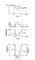
- Fig. 3 the outputs O1 and O2 of the first and second filters 14 and 20 are shown. Prior to a time t0 and after a time t1 one can see that the outputs of the first and second filters are similar, correspond to times when the flow is relatively steady and, as can be seen from Fig. 4, the time constant of the second filter 20 is at its maximum.
- the difference amplifier circuit 19 followed by the absolute value circuit 18 provide a signal /O1-O2/ shown in the upper portion of Fig. 4 which is the absolute value of the difference between the first and second filter outputs.
- deadband selector 15 has received the output O1 of the first filter and has selected an appropriate deadband automatically by comparing the signal O1 to preset voltages. Therefore, if a very high feed rate is being sensed, the deadband will be at a high value, whereas if a very low feed rate is being sensed, the deadband selector will select a lower deadband value.
- a middle range deadband is also provided for middle range flow rates.
- the appropriate deadband is automatically selected by comparing O1 to present voltages which are proportioned to the feed rates and as the flow rates change, a transition from one deadband to the next is made.
- the selected deadband is exceeded, as is shown by the horizontal dashed line in the upper part of Fig. 4, this is sensed by deadband comparator 17 and the output along line 46 is varied so that the pulse width modulator 21 starts applying pulses at its output which increase in pulse width from a minimum pulse width to a maximum pulse width.
- a lag time effecting the change from maximum time constant to minimum time constant (lag 1) and from minimum time constant to maximum time constant (lag 2) is preferably set by two first order lag circuits which comprise a part of the deadband comparitor.
- the time constant of the second filter 20 is varied by duty cycling its frequency determining resistors. Duty cycling is accomplished by using the pulse width modulated signal whose pulse width is proportional to the rising or falling DC output of the deadband comparator.
- the output O2 of the second filter 20 preferably is not sent immediately to signal scaler 23 because, due to filtering delays, output O2 delays the first filter's output O1 in time as indicated in Fig. 3.
- a faster response is provided by using the same pulse width modulated signal from pulse width modulator 21 on line 48 to blend the first and second filter outputs O1 and O2 in output blender 22.
- the signal sent to the signal scaler 23 on line 51 is comprised entirely of the second filter output O2. After t0 when flow begins to decrease and /O1-O2/ exceeds the deadband, the fraction of O2 sent to the display decreases while the fraction of O1 increases.
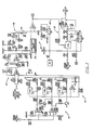
- Figures 6 and 7 are diagrams of some of the specific circuitry shown in block diagram form shown in Fig. 2.
- Figure 6 shows a circuit for the second filter 20.
- Figure 7 illustrates difference circuit 19, absolute value circuit 18, dead band selector 15, dead band generator 16, dead band comparitor 17, pulse width modulator 21 and output blender 22.
- conventional circuitry such as power supply voltages and associated capacitors and the like associated with operational amplifiers are omitted; it will be appreciated that one skilled in the art will readily be able to include those elements.
- Sallen-Key filters are given in such references as "Active-Filter Cookbook” by Don Lancaster (Howard W. Sams & Co., Inc., 1st. ed. 1975).
- a preferred embodiment for filter 20 is illustrated in Fig. 6.
- the second filter, a sixth order, low pass Sallen-Key filter with a voltage controlled cutoff frequency utilizes four ultra-low input bias current operational amplifiers U107a-d in series.
- the preferred technique is to use four conventional bilateral analog switches U106a-d to duty cycle frequency-determining resistors R138, R139, R142, R143, R145, R146, R147, and R148. The switches are driven by the output of pulse width modulator 21 via line 47.
- the four Sallen-Key filters in circuit 20 are cascaded in pairs, each pair having a series resistance and capacitor feedback led from the output of the second operational amplifier to the positive input of the first operational amplifier; i.e., for the first stage from the U107b output through C131 and R144 to the U107a positive input, and similarly from U107d through C134, R150 to U107c.
- the remaining resistors R139, R143, R146, R148 and capacitors C128, C130, C132, C133 in curcuit 20 complete the frequency determining circuitry.
- the pulse width modulator 21 shown in Fig. 7 includes a saw tooth generator 21a which may be of any conventional type which produces a sawtooth waveform at an amplitude of 5 VDC and a frequency substantially higher than the cutoff frequency of the second filter; e.g. at least 10 times and preferably 75 to 100 times higher, such as 30 Hz.
- the sawtooth waveform produced from this circuit is fed to one input of an operational amplifier U1a whose other input is the output of deadband comparator 17 as will be explained hereinafter.
- U1a operational amplifier
- a variable pulse width output signal will be obtained which is applied via line 47 to the variable time constant second filter 20 as shown in Fig. 2.
- the pulse width modulator signal on line 47 from the output of circuit 21 is fed via connection N to the control input of the four analog switches U106 of circuit 20 (Fig. 6).
- Control inputs to analog switches are designated “ci" in Figs. 6 and 7.
- Each switch has disposed in parallel therewith a 22 megohm time-constant resistors R138, R142, R145, R147 so that, when the switch is closed by a pulse, this resistor is short circuited (by-passed) and, when the switch is open, the resistor is in series with the remaining RC time constant resistors and capacitors R139, R143, R144, R146, R148, R150 and capacitors C128, C130, C131, C132, C133, C134.
- the effective time constant of the filter will be established in dependence upon the duty cycle time during each cycle of the modulated sawtooth signal that the switches are closed and open and therefore the 22 megohm resistors are out of the circuit to produce the minimum time constant of, e.g., 3-4 seconds or are in the circuit to produce the maximum time constant of, e.g., 60 seconds.
- the difference circuit 19 (Fig. 2) is formed conventionally with a general purpose operational amplifier in a unity gain configuration.
- the absolute value circuit 18, connected to the output O1-O2 of difference circuit 19, is also a conventional inverting operational amplifier type circuit with unity gain and feeds its signal /O1-O2/ as a negative voltage via line 43 to deadband comparator 17 which processes /O1-O2/ as well as sends /O1-O2/ on line 43 to deadband generator 16 as described hereinbelow.
- Deadband selector 15 has as its input the output of first filter 14 via line 38, which output is placed into two comparator circuits comprising two operational amplifiers U3a, U3b with resistors R26, R33 and diode D13. At the other inputs of each of the amplifiers are two reference voltages obtained by a voltage divider comprising resistors R23, R24, R25 so that the input signal O1 is compared to the two reference voltages.
- the two comparator circuits in conjunction with two switching transistors Q1, Q2 activate one of three analog switches U4a, U4b, U4c.
- the corresponding deadband value is thereby chosen by the signal from O1 turning on one of the analog switches which puts the appropriate feedback network A, B or C on line 43 into deadband generator circuit 16.
- Circuit 16 has at its input at R49 /O1-O2/ (via line 43) which is always a negative signal.
- Amplifier U3c in combination with R49 and the selected feedback loop A, B or C is configurated as an inverting amplifier so that its output is always positive.
- the gain of amplifier U3c and consequently the deadband value is set by the selected feed back loop A,B or C.
- U3c amplifies /O1-O2/ by an amount dependent on the selected deadband value so that, when /O1-O2/ reaches the deadband value, the output of U3c will forward bias the diode D5 to a voltage sufficient for the diode to conduct and supply current back to circuit 17 through line 43 to the non-inverting input of U2b.
- the deadband generator therefore has the effect of placing a limit on the non-inverting input of U2b in circuit 17 at the selected deadband value through line 43 so that, as /O1-O2/ exceeds the deadband, output from circuit 16 causes the inputs of U2b to become unbalanced, causing its output to become non-zero.
- Deadband ranges are chosen corresponding to a powder feed rate range of, for example, 0 to 5, 5 to 20, or 20 to 100 pounds per hour.
- a corresponding deadband value and, therefore, response sensitivity of, for example, 0.3, 0.75 and 1.5 pounds per hour is to be automatically selected depending upon the amplitude of output O1 of the first filter 14.
- Other values for R23-R25 may be chosen for other feed rate ranges, and other values for R31, R37 and R42 may be selected for other deadband values and sensitivities.
- the signal, if any, from U2b is processed by the operational amplifier U2a, resistors R10-R21 and a 22 microfarad capacitor C3 and diodes D3, D4 to obtain the output voltage signal for feeding into the pulse width modulator 21.
- the next amplifier U2a with resistors R10-R12 is configured as a non-inverting amplifier with a gain of approximately 100 so that, even for small input signals from U2b, its output will saturate positive when the selected deadband value is exceeded.
- a high positive output from amplifier U2a biases the resistor network R13-R21 and causes the output voltage on C3 to charge through resistors R15, R18 and R19 and diode D4 from zero to approximately 7 VDC over a lag 1 time period (Figs. 4 and 5) of preferably about 15 seconds.
- a lag 1 time period Figs. 4 and 5
- the output of U2a is zero and C3 will discharge through resistors R21, R20, R16, and R13 over a lag 2 time period of preferably 30 seconds.
- Resistor 14 is in the circuit to force the junction of R13, R16, R20 and D3 to ground or below if the input offset voltage of U2a is positive. This assures that C22 discharges fully so that the pulse width goes to zero.
- the voltage imposed on C3 sets the control voltage on line 46 to amplifier U1a of pulse width molulator 21.
- the voltage from curcuit 17 thus modulates the sawtooth wave in operational amplifier U1a providing the pulsed control signal output on line 49 and, through connector N, to analog switches U106 in the second filter circuit 20 (Fig. 6), with effects as described hereinabove.
- a high voltage from circuit 17 corresponds to wide pulse width and a resulting short time constant for the second filter 20, and a low voltage corresponds to narrow pulse width and a resulting long time constant.
- the phrases "wide pulse width” and “narrow pulse width” as used herein and in the claims refer to the respective pulse widths necessary to duty cycle analog switches U106 (Fig. 6) for the required minimum or maximum time constant.
- the outputs of the two filters 14 and 20 are then fed to the output blending circuit 22 having an analog switch U6a which is duty cycled by the output of pulse width modulator 21 by feeding its control signal on line 49 to the control input of analog switch U6a.
- analog switch U6a selectively passes signal O1 from filter 14 to combine with and override signal O2 which is received from filter 20 via connection M.
- the analog switch is followed by a low pass unity gain Sallen-Key filter including operational amplifier U5a, resistors R59-R61 and capacitors C8, C9 which smooth the blended output.
- the output is thereafter processed by scaling circuit 23 (Fig. 2) which consists of a standard voltage divider configuration. As previously indicated, the scaler output is then presented to display 1 (Figs. 1 and 2) for display of powder feed rate.
- Switch S1 (Fig. 7) is normally closed during idle of the circuits, without powder feeding, providing a voltage through resistor R53 and diode D9 to U1a to set a high pulse width output.
- power from a power supply PS for the feeder is simultaneously fed to solenoid K1 that opens S1, transferring the source of input to U1a over to circuit 17.
Landscapes
- Physics & Mathematics (AREA)
- General Physics & Mathematics (AREA)
- Networks Using Active Elements (AREA)
- Measuring Volume Flow (AREA)
- Weight Measurement For Supplying Or Discharging Of Specified Amounts Of Material (AREA)
Applications Claiming Priority (2)
| Application Number | Priority Date | Filing Date | Title |
|---|---|---|---|
| US06/927,012 US4730499A (en) | 1986-11-04 | 1986-11-04 | Measurement of flow rate of powder from a hopper |
| US927012 | 1986-11-04 |
Publications (3)
| Publication Number | Publication Date |
|---|---|
| EP0266761A2 true EP0266761A2 (de) | 1988-05-11 |
| EP0266761A3 EP0266761A3 (de) | 1991-01-02 |
| EP0266761B1 EP0266761B1 (de) | 1994-05-18 |
Family
ID=25454030
Family Applications (1)
| Application Number | Title | Priority Date | Filing Date |
|---|---|---|---|
| EP87116259A Expired - Lifetime EP0266761B1 (de) | 1986-11-04 | 1987-11-04 | Messung der Durchflussgeschwindigkeit von Pulver aus einem Fülltrichter |
Country Status (7)
| Country | Link |
|---|---|
| US (1) | US4730499A (de) |
| EP (1) | EP0266761B1 (de) |
| JP (1) | JPH0690069B2 (de) |
| CN (1) | CN1012532B (de) |
| BR (1) | BR8705939A (de) |
| CA (1) | CA1297588C (de) |
| DE (1) | DE3789850T2 (de) |
Cited By (1)
| Publication number | Priority date | Publication date | Assignee | Title |
|---|---|---|---|---|
| GB2248695A (en) * | 1990-09-28 | 1992-04-15 | Pall Corp | Flow meter |
Families Citing this family (17)
| Publication number | Priority date | Publication date | Assignee | Title |
|---|---|---|---|---|
| US4954975A (en) * | 1988-08-10 | 1990-09-04 | K-Tron International, Inc. | Weigh feeding system with self-tuning stochastic control and weight and actuator measurements |
| JPH02146911A (ja) * | 1988-11-28 | 1990-06-06 | Ushio Inc | 電線の絶縁被覆の抜取り方法 |
| US5029658A (en) * | 1990-04-12 | 1991-07-09 | Clintec Nutrition Co. | Mass/weight measurement filtering system |
| US5739429A (en) * | 1995-07-13 | 1998-04-14 | Nordson Corporation | Powder coating system incorporating improved method and apparatus for monitoring flow rate of entrained particulate flow |
| US5780780A (en) * | 1997-01-17 | 1998-07-14 | Ahmed; Gulzar | Weighing vibratory apparatus and method |
| JPH11108751A (ja) * | 1997-10-08 | 1999-04-23 | Ishida Co Ltd | フィルタ自動調整機能付き計量装置 |
| US6313415B1 (en) * | 1999-12-30 | 2001-11-06 | Pitney Bowes Inc. | Pulse width modulated weighing platform |
| US6810366B2 (en) * | 2002-03-25 | 2004-10-26 | Caterpillar Inc | Method and apparatus for filtering a signal using a deadband |
| JP5073949B2 (ja) * | 2006-02-02 | 2012-11-14 | 日立オートモティブシステムズ株式会社 | 流量測定装置 |
| US7534970B2 (en) * | 2006-06-15 | 2009-05-19 | Schenck Accurate, Inc. | Counterbalanced dispensing system |
| DE102008051040B4 (de) * | 2008-10-09 | 2012-10-04 | Siemens Aktiengesellschaft | Verfahren zur Materialflussüberwachung für kontinuierliche Wägungen |
| FR2941576B1 (fr) * | 2009-01-28 | 2016-07-15 | St Wireless Sa | Procede et systeme de calibration d'une constante de temps integree, et circuit integre pourvu d'un tel systeme |
| JP2017511480A (ja) | 2014-03-31 | 2017-04-20 | ユニヴァーシティー オブ ユタ リサーチ ファウンデーション | 液解析デバイスならびに関連するシステムおよび方法 |
| JP6521224B2 (ja) * | 2015-02-26 | 2019-05-29 | 大和製衡株式会社 | 搬送計量装置 |
| US10401246B2 (en) | 2017-05-31 | 2019-09-03 | Oerlikon Metco (Us) Inc. | Powder feed control system and method |
| US10815064B1 (en) | 2017-12-22 | 2020-10-27 | Gulzar Ahmed | Systems and methods for controlling the dispensing of articles |
| CN109580983A (zh) * | 2018-12-17 | 2019-04-05 | 苏州宇量电池有限公司 | 一种锂离子电池浆料的过筛流速测定方法 |
Citations (3)
| Publication number | Priority date | Publication date | Assignee | Title |
|---|---|---|---|---|
| EP0029236A1 (de) * | 1979-11-19 | 1981-05-27 | Mtu Motoren- Und Turbinen-Union MàNchen Gmbh | Vorrichtung zum thermischen Verspritzen von Metall- und Keramikpulvern |
| EP0062205A2 (de) * | 1981-04-07 | 1982-10-13 | Bizerba-Werke Wilhelm Kraut GmbH & Co. KG. | Elektronische Wägevorrichtung |
| FR2554584A1 (fr) * | 1983-11-09 | 1985-05-10 | Sartorius Gmbh | Balance electrique equipee de dispositifs electroniques de detection et d'affichage |
Family Cites Families (5)
| Publication number | Priority date | Publication date | Assignee | Title |
|---|---|---|---|---|
| US3855458A (en) * | 1973-08-21 | 1974-12-17 | Toroid Corp | Flow meter |
| DE2500094C3 (de) * | 1975-01-03 | 1979-03-22 | Richard Wolf Gmbh, 7134 Knittlingen | Gerät zur elektrischen Messung von Urinströmmengen |
| US4320855A (en) * | 1976-12-07 | 1982-03-23 | Acrison, Incorporated | Weigh feeding apparatus |
| US4277022A (en) * | 1977-04-19 | 1981-07-07 | Dennis W. Holdsworth | Mobile material distribution system |
| US4561808A (en) * | 1984-06-04 | 1985-12-31 | Metco Inc. | Powder feed pickup device for thermal spray guns |
-
1986
- 1986-11-04 US US06/927,012 patent/US4730499A/en not_active Expired - Lifetime
-
1987
- 1987-11-04 EP EP87116259A patent/EP0266761B1/de not_active Expired - Lifetime
- 1987-11-04 BR BR8705939A patent/BR8705939A/pt not_active IP Right Cessation
- 1987-11-04 JP JP62277558A patent/JPH0690069B2/ja not_active Expired - Lifetime
- 1987-11-04 DE DE3789850T patent/DE3789850T2/de not_active Expired - Lifetime
- 1987-11-04 CA CA000551063A patent/CA1297588C/en not_active Expired - Lifetime
- 1987-11-04 CN CN87107659A patent/CN1012532B/zh not_active Expired
Patent Citations (3)
| Publication number | Priority date | Publication date | Assignee | Title |
|---|---|---|---|---|
| EP0029236A1 (de) * | 1979-11-19 | 1981-05-27 | Mtu Motoren- Und Turbinen-Union MàNchen Gmbh | Vorrichtung zum thermischen Verspritzen von Metall- und Keramikpulvern |
| EP0062205A2 (de) * | 1981-04-07 | 1982-10-13 | Bizerba-Werke Wilhelm Kraut GmbH & Co. KG. | Elektronische Wägevorrichtung |
| FR2554584A1 (fr) * | 1983-11-09 | 1985-05-10 | Sartorius Gmbh | Balance electrique equipee de dispositifs electroniques de detection et d'affichage |
Cited By (1)
| Publication number | Priority date | Publication date | Assignee | Title |
|---|---|---|---|---|
| GB2248695A (en) * | 1990-09-28 | 1992-04-15 | Pall Corp | Flow meter |
Also Published As
| Publication number | Publication date |
|---|---|
| CN1012532B (zh) | 1991-05-01 |
| CA1297588C (en) | 1992-03-17 |
| BR8705939A (pt) | 1988-06-14 |
| JPS63124920A (ja) | 1988-05-28 |
| DE3789850T2 (de) | 1994-09-01 |
| US4730499A (en) | 1988-03-15 |
| JPH0690069B2 (ja) | 1994-11-14 |
| CN87107659A (zh) | 1988-05-18 |
| EP0266761A3 (de) | 1991-01-02 |
| EP0266761B1 (de) | 1994-05-18 |
| DE3789850D1 (de) | 1994-06-23 |
Similar Documents
| Publication | Publication Date | Title |
|---|---|---|
| EP0266761B1 (de) | Messung der Durchflussgeschwindigkeit von Pulver aus einem Fülltrichter | |
| US3643753A (en) | Electrical filters for weighing system circuits | |
| US3430751A (en) | Variable speed feeder control | |
| CA1055004A (en) | Automatically controlled weigh feeding apparatus | |
| GB1584887A (en) | Weigh feeding machine | |
| NO821228L (no) | Passivt telemetrisystem. | |
| US3754126A (en) | Integrating conveyor scale | |
| US3464508A (en) | Force transducer output measuring system employing ratio technique | |
| CA1136166A (en) | Electronic weight measuring device | |
| CA1250357A (en) | Three-terminal controller for fiber glass bushing | |
| US3942625A (en) | Portable conveyor load measuring apparatus | |
| US3565193A (en) | Electrical weigher using vibrating strings | |
| US3892045A (en) | Fuel allocation system and method for industrial dryers and the like | |
| US2997205A (en) | Method and apparatus for controlling discharge of materials | |
| GB2207929A (en) | Apparatus for fibre preparation | |
| US3062408A (en) | Apparatus for feeding materials at a regulated rate | |
| KR100370573B1 (ko) | 정량불출기의 불출량 조정장치 | |
| US4582150A (en) | Automated, integrated, filling, check weighing, and self-correcting bagging apparatus and method | |
| SU1762826A1 (ru) | Способ управлени дозирующим механизмом и устройство дл его осуществлени | |
| GB2190506A (en) | Weighing device | |
| US3380000A (en) | Voltage controlled relaxation oscillator | |
| SU951082A1 (ru) | Весовой дозатор непрерывного действи | |
| SU1643951A1 (ru) | Способ автоматического непрерывного весового дозировани компонентов шихты | |
| JPS5813853B2 (ja) | 粉体供給機における粉体の瞬間重量流量計測方法及び瞬間重量流量計 | |
| US3719078A (en) | Linear output boat speedometer |
Legal Events
| Date | Code | Title | Description |
|---|---|---|---|
| PUAI | Public reference made under article 153(3) epc to a published international application that has entered the european phase |
Free format text: ORIGINAL CODE: 0009012 |
|
| AK | Designated contracting states |
Kind code of ref document: A2 Designated state(s): CH DE FR GB IT LI |
|
| PUAL | Search report despatched |
Free format text: ORIGINAL CODE: 0009013 |
|
| AK | Designated contracting states |
Kind code of ref document: A3 Designated state(s): CH DE FR GB IT LI |
|
| 17P | Request for examination filed |
Effective date: 19910702 |
|
| 17Q | First examination report despatched |
Effective date: 19920810 |
|
| GRAA | (expected) grant |
Free format text: ORIGINAL CODE: 0009210 |
|
| AK | Designated contracting states |
Kind code of ref document: B1 Designated state(s): CH DE FR GB IT LI |
|
| ITF | It: translation for a ep patent filed |
Owner name: ING. A. GIAMBROCONO & C. S.R.L. |
|
| REF | Corresponds to: |
Ref document number: 3789850 Country of ref document: DE Date of ref document: 19940623 |
|
| ET | Fr: translation filed | ||
| PLBE | No opposition filed within time limit |
Free format text: ORIGINAL CODE: 0009261 |
|
| STAA | Information on the status of an ep patent application or granted ep patent |
Free format text: STATUS: NO OPPOSITION FILED WITHIN TIME LIMIT |
|
| 26N | No opposition filed | ||
| REG | Reference to a national code |
Ref country code: CH Ref legal event code: PUE Owner name: THE PERKIN-ELMER CORPORATION TRANSFER- SULZER METC |
|
| REG | Reference to a national code |
Ref country code: GB Ref legal event code: 732E |
|
| REG | Reference to a national code |
Ref country code: FR Ref legal event code: TP |
|
| REG | Reference to a national code |
Ref country code: GB Ref legal event code: IF02 |
|
| PGFP | Annual fee paid to national office [announced via postgrant information from national office to epo] |
Ref country code: CH Payment date: 20061114 Year of fee payment: 20 |
|
| PGFP | Annual fee paid to national office [announced via postgrant information from national office to epo] |
Ref country code: DE Payment date: 20061124 Year of fee payment: 20 Ref country code: FR Payment date: 20061124 Year of fee payment: 20 |
|
| PGFP | Annual fee paid to national office [announced via postgrant information from national office to epo] |
Ref country code: GB Payment date: 20061127 Year of fee payment: 20 |
|
| PGFP | Annual fee paid to national office [announced via postgrant information from national office to epo] |
Ref country code: IT Payment date: 20061130 Year of fee payment: 20 |
|
| REG | Reference to a national code |
Ref country code: GB Ref legal event code: PE20 |
|
| REG | Reference to a national code |
Ref country code: CH Ref legal event code: PL |
|
| PG25 | Lapsed in a contracting state [announced via postgrant information from national office to epo] |
Ref country code: GB Free format text: LAPSE BECAUSE OF EXPIRATION OF PROTECTION Effective date: 20071103 |