EP0266239B1 - Waschmaschine mit einer Manschette zur Verbindung des Laugenbehälters mit dem Gehäuse - Google Patents
Waschmaschine mit einer Manschette zur Verbindung des Laugenbehälters mit dem Gehäuse Download PDFInfo
- Publication number
- EP0266239B1 EP0266239B1 EP87402146A EP87402146A EP0266239B1 EP 0266239 B1 EP0266239 B1 EP 0266239B1 EP 87402146 A EP87402146 A EP 87402146A EP 87402146 A EP87402146 A EP 87402146A EP 0266239 B1 EP0266239 B1 EP 0266239B1
- Authority
- EP
- European Patent Office
- Prior art keywords
- machine
- groove
- opening
- tongues
- edge
- Prior art date
- Legal status (The legal status is an assumption and is not a legal conclusion. Google has not performed a legal analysis and makes no representation as to the accuracy of the status listed.)
- Expired - Lifetime
Links
- 238000005406 washing Methods 0.000 title claims description 20
- 238000007789 sealing Methods 0.000 claims abstract description 15
- 210000002105 tongue Anatomy 0.000 claims description 49
- 239000007788 liquid Substances 0.000 claims description 6
- 230000002093 peripheral effect Effects 0.000 claims description 4
- 206010016322 Feeling abnormal Diseases 0.000 abstract 2
- 239000011324 bead Substances 0.000 description 13
- 230000014759 maintenance of location Effects 0.000 description 6
- 230000010355 oscillation Effects 0.000 description 5
- 238000009432 framing Methods 0.000 description 2
- 241000206607 Porphyra umbilicalis Species 0.000 description 1
- 239000003599 detergent Substances 0.000 description 1
- 230000008030 elimination Effects 0.000 description 1
- 238000003379 elimination reaction Methods 0.000 description 1
- 238000009434 installation Methods 0.000 description 1
- 238000004519 manufacturing process Methods 0.000 description 1
- 239000000463 material Substances 0.000 description 1
- 238000000926 separation method Methods 0.000 description 1
- 229920002994 synthetic fiber Polymers 0.000 description 1
Images
Classifications
-
- D—TEXTILES; PAPER
- D06—TREATMENT OF TEXTILES OR THE LIKE; LAUNDERING; FLEXIBLE MATERIALS NOT OTHERWISE PROVIDED FOR
- D06F—LAUNDERING, DRYING, IRONING, PRESSING OR FOLDING TEXTILE ARTICLES
- D06F37/00—Details specific to washing machines covered by groups D06F21/00 - D06F25/00
- D06F37/26—Casings; Tubs
- D06F37/266—Gaskets mounted between tub and casing around the loading opening
-
- D—TEXTILES; PAPER
- D06—TREATMENT OF TEXTILES OR THE LIKE; LAUNDERING; FLEXIBLE MATERIALS NOT OTHERWISE PROVIDED FOR
- D06F—LAUNDERING, DRYING, IRONING, PRESSING OR FOLDING TEXTILE ARTICLES
- D06F37/00—Details specific to washing machines covered by groups D06F21/00 - D06F25/00
- D06F37/26—Casings; Tubs
Definitions
- the present invention relates to a washing machine with a tank-body connection sleeve.
- a washing machine usually comprises a body in which is suspended a tub containing a washing drum. Between the opening of the machine and the opening of the tank is mounted a flexible cuff which provides both access to the tank and a liquid-tight separation between the interior of the bodywork and the interior of the tank.
- the suspended tank is subject to oscillations during the operation of the machine and the flexible cuff must be securely fixed to the body and to the tank so that it can follow the tank in its movements and resist any tearing caused by these oscillations.
- edges of the two ends of the flexible cuff are maintained either by clamps mounted around the opening of the machine and the opening of the tank, or by retention grooves formed around these openings into which these edges are forcibly inserted, either by screw and bar fastening systems or rigid frames.
- Document DE-A-3 220 577 gives an example of a flexible cuff, the edges of the two ends of which are held by retention grooves formed around the opening of the machine and the opening of the tank.
- the edges of the end of the cuff connected to the opening of the machine are partly sliding along the sections of the retention groove formed around this opening of the machine parallel to the direction of rotation of the drum.
- the aim of the present invention is to avoid these drawbacks and makes it possible to produce an economical washing machine in which the flexible body-tank connection cuff is securely fixed and ensures good liquid tightness between the interior of the body and the inside the tank, and between the inside of the tank and the outside of the machine, and the positioning of this flexible sleeve is easily mechanizable.
- a washing machine provided between the tank and the body of a connecting cuff whose edges of the two ends are held by grooves or grooves formed around the opening of the machine and the opening of the tank is characterized in that it comprises at least on the one hand in the periphery of the edge of the opening of the machine and / or of the opening of the tank, a groove provided with spaced mortises provided with members self-locking non-return, and on the other hand along the upper and / or lower end of the flexible cuff, a projecting rim intended to be mounted in this groove, and provided in the first place with spaced studs associated with these mortises and each comprising a receiving groove, flexible parallel longitudinal sealing lips in the spaces above and between two consecutive studs.
- the invention is applicable to washing machines provided with a rectangular or circular opening and with a tub with rectangular or circular opening.
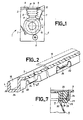
- a washing machine 1 schematically illustrated in Figure 1 to 4 comprises a body 2 provided with a top wall of synthetic material 3, a rectangular opening 4 of the machine formed in this wall 3, a pivoting door 5 a plastic tank 6 suspended in the body 2 by springs 7 and provided with a rectangular opening 8, and, a flexible cuff 9 connecting the rectangular opening 4 of the machine and the 'rectangular opening 8 of the tank 6 to separate, in a liquid-tight manner on the one hand the interior of the body 2 and the interior of the tank and on the other hand the exterior of the machine and the inside of the tank 6.
- the tank 6 contains a laundry drum 10 which is rotated by an electric motor 11.
- the flexible cuff 9 in the form of a flexible tube provided with transverse folds comprises an upper end 12 fixed to the edge of the opening 4 of the machine and a lower end 13 attached to the edge of the opening 8 of the tank 6 .
- the washing machine 1 comprises at least on the one hand around the edge of the opening 4 of the machine and / or the opening 8 of the tank 6 of the machine, a groove with smooth walls provided with spaced mortises provided with self-locking non-return member and on the other hand along the upper and / or lower end of the flexible cuff 9 a protruding rim intended to be mounted in this groove, provided in the first place spaced studs associated with the mortises of the groove of the edge of the opening 4 of the machine and / or of the opening 8 of the tank 6 of the machine, and each comprising a groove for receiving this self-locking non-return member of these mortises and secondly, in the spaces above and between two consecutive tenons, of flexible parallel longitudinal sealing lips.
- the washing machine 1 comprises on the one hand in the inner periphery of the lower end of the flexible cuff 9, a skirt 15 intended to cover the inner wall of the edge of the opening 8 of the tank 6 for aesthetic purposes and elimination of any catching with linen introduced into the tank and of any retention of liquid or detergents, and in the inner periphery of the upper end of the flexible cuff 9, a lip d horizontally projecting seal 16 and on the other hand in the inner face of the pivoting door 5 of the machine, a sealing rib 17 framing the opening 4 of the machine and cooperating with this projecting lip 16 of the upper end of the flexible sleeve 9 to seal the liquid between the outside of the machine and the inside of the tank.
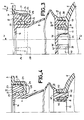
- the washing machine 1 comprises in the periphery of the edge of the rectangular opening 4 of the machine, a groove 19 with internal side walls 20 and external 21 smooth, provided with spaced mortises 22 which open through the bottom wall 23 and the external side wall 21 of the groove 19 and which are each provided with a self-locking non-return member constituted by an elastic tongue 24, inclined towards the inside of this groove 19 d 'an angle alpha with respect to the vertical, and forming an integral part of this external lateral wall 21 of the groove 19.
- the flexible cuff 9 comprises in the periphery of its upper end 12, a flexible projecting rim 25 intended to be mounted in the groove 19 of the edge of the opening 4 of the machine.
- This projecting rim 25 comprises along its length spaced tenons 26 associated with the mortises 22 of the groove 19 of the edge of the opening 4 of the machine and intended to retain this protruding rim 25 in this groove 19 and therefore the end upper of the flexible cuff 9, on the edge of this opening 4 of the machine.
- the spaced tenons 26 each comprise on the one hand a body with a cross section substantially in a rectangular trapezoid, having a face 27 cooperating with the elastic tongue 24, inclined in the same direction as that of the inclination of this tongue 24, and according to a angle beta with respect to the vertical, equal to the angle alpha that this tongue 24 makes with the vertical, and on the other hand at its free end a terminal bead 28 which defines with this inclined face 27 a groove 29 for receiving the 'end of this tongue 24 which constitutes the self-locking non-return member of the corresponding mortise.
- the elastic tongue 24 When a tenon 28 of the upper end 12 of the flexible cuff 9 is introduced into a mortise 22, the elastic tongue 24 is displaced, disappears, lets the bead 28 pass and allows its tenon 26 to be put in place. given that the angle beta of the inclined face 27 of the tenon 26 is equal to the angle alpha of the normal inclination of the elastic tongue 24, the tongue 24 follows this inclined face 27 when this tenon is put in place 26. The tongue 24 is then in place on the tenon 26 to hold it in the groove 19. During the oscillations of the suspended tank 6, the cuff 9 is subjected to pulls which tend to pull the tenons 26 out of mortises 22.
- the beads 28 and the grooves 29 hook the free ends of the tongues 24 and cause them to move so that the more the tenons 26 are pulled towards the outside of the mortises, the more these tongues 24 close at utomatically more mortises 22, at the same time increase their pressure on these tenons 26 and prevent them from coming out of these mortises.
- the upper end of the flexible cuff 9 is thus securely attached to the edge of the opening 4 of the machine.
- the flexible projecting rim 25 of the cuff 9 comprises flexible longitudinal sealing lips 31 which conform to the slightest surface irregularities of the groove 9 and thus increase the intimacy of contact between this protruding rim 25 clamped in the groove 19 and the wall of the latter and ensure there a good liquid tightness.
- the pins 26 comprise at their free ends, in their part diametrically opposite to their beads 28 of the longitudinal ribs 33 intended to be hung on the edges of the mortises 22 when the pins 26 are properly positioned in these mortises. These ribs 33 also help to prevent the studs from being easily removed from the mortises 22.
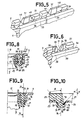
- the tank 6 comprises, around its rectangular opening 8, a groove 36 with an internal side wall 37 and extrene 38 smooth, provided with spaced mortises 39 which open through the bottom wall 40.
- the flexible cuff 9 comprises in the periphery of its lower end 13, a flexible projecting rim 41 intended to be fitted tightly in the groove 36 of the edge of the opening 8 of the tank 6.
- This projecting rim 41 includes tenons along its length spaced 42 associated with the mortises 39 of the groove 36 and intended to retain this protruding rim 41 in this groove and therefore the lower end of the flexible cuff 9 on the edge of the opening 8 of this tank 6.
- the spaced studs 42 each comprise on the one hand a body with a substantially rectangular cross section, and on the other hand at its free end, a peripheral bead projecting laterally 43.
- the beads 43 hang on the edge of the mortises 39 when the tenons 42 are placed in them, and prevent these tenons 42 from being removed from these mortises by simple and weak traction.
- the lower end of the flexible cuff 9 is thus securely attached to the edge of the opening 8 of the tank 6.
- the flexible projecting rim 41 includes flexible longitudinal sealing lips 45 which conform to the slightest surface irregularities of the groove 36 and thus reinforce the contact intimacy between this projecting rim 41 packed in this groove and the wall of the latter and ensure good liquid tightness.
- the washing machine 1 comprises, in the periphery of the edge of the opening 8 of the tank 6 and / or of the opening 4 of the machine, a groove 36 at internal 37 and external 38 smooth side walls, provided with spaced mortises 39 in which, the two spaced parallel vertical notches 46 found in the first example (FIGS.
- each of the mortises 39 in the face outside of the internal wall 37 of the groove 36 are respectively replaced by a vertical notch 48 formed at a first lateral side of each of the mortises 39, in the internal wall 37 of the groove 36, and open in this mortise 39, and by a transverse cutout 49 in this internal wall 37 of the groove 36 at the level of the second lateral side of this mortise 39.
- the cutout 49 and the notch 48 transform the has internal wall 37, at the mortise 39, in an elastic lug 52 which serves as a self-locking non-return member.
- the elastic lug 52 exerts pressure on the corresponding associated tenon 42 of the protruding rim 41 and firmly retains this rim in the groove, 36 by cohesion of this tenon 42 at the level of the protruding peripheral flange 43 of the latter.
- the notch 48 gives a good lateral tightness to the lug 52 and facilitates the mounting of the lug 42 of the cuff 9 in the mortise 39 without compromising the vertical rigidity of this lug 52 which is opposed to an unexpected withdrawal of the latter lug 42.
- the washing machine 1 comprises, in the periphery of the edge of the opening 8 of the tank 6 and / or of the opening 4 of the machine, a groove 36 provided with spaced mortises 39 in which the two spaced parallel vertical notches 46 formed at the lateral sides of each of the mortises 39 in the outer face of the internal wall 37 of the groove 36, found in the first example ( Figures 3 and 4) are respectively replaced on the one hand by two spaced parallel vertical notches 50 open in the mortise 39, formed in the internal wall 37 of the groove 36 at the two lateral sides of this mortise, and on the other hand by a transverse cut 51 in the internal side wall 37 at the central zone of the mortise 39, that situated between these two parallel vertical notches 50.
- the cutout 51 transforms the has internal wall 37 of the groove, at the level of the mortise 39, in two elastic lugs 52, 54 which serve as self-locking non-return member. These lugs exert pressure on the corresponding tenon 42 of the protruding rim 41 and firmly retains this rim in the groove 36 by wedging this tenon 42 at its protruding bead 43.
- the notches 50 give good lateral elasticity to the lugs 53, 54 and facilitate the mounting of the tenon 42 of the cuff 9 in the mortise 39 without reducing the vertical stiffness of these lugs 53, 54 which oppose an unexpected withdrawal of these tenons 42.
- the washing machine 1 comprises, in the periphery of the edge of the opening 4 of the machine and / or of the opening 8 of the tank 6, a groove 19 with side walls internal 20 and external 21 smooth, provided with spaced mortises 57 which open through its two internal side walls 20 and external 21 and its bottom wall 23 and which are each provided with a self-locking non-return member constituted by two opposite lateral tabs symmetrical elastic 59, 60, inclined and converging towards the inside of this groove 19 respectively at an angle alpha with respect to the vertical and forming an integral part respectively of the internal walls 20 and external 21 of this groove.
- the flexible cuff 9 comprises, around the upper end 12 and / or lower 13, a flexible projecting rim 25 provided along its length with spaced studs 61 associated with the mortises 57 of the groove 19 of the edge of the opening 4 of the machine and / or the opening 8 of the tank 6 and intended to retain this protruding rim 25 in this groove 19.
- the spaced studs 61 each comprise on the one hand a body with a substantially trapezoidal cross section isosceles having two symmetrical opposite faces 63, 64, cooperating with the two symmetrical opposite elastic lateral tongues 59, 60, inclined respectively in the same directions as those of the inclinations of the symmetrical opposite tongues 59, 60 and respectively at a beta angle with respect to the vertical, less than the angle alpha made by the tongues 59, 60 with the vertical, and on the other hand at its free end, two end beads 65, 66 which respectively define with these two inclined faces 63, 64, two grooves 67, 68 for receiving the ends of these tongues serving as a self-locking non-return member.
- the end beads 65, 66 of these tenons hook the free ends of the symmetrical tabs 59, 60 and cause them to move so that more tenons 61 are pulled towards the outside of the mortises 57, the more these tabs approach each other, close these mortises 57 more, increase their pressure on these tenons and prevent them from coming out of these mortises.
- the end of the flexible cuff 9 is thus securely attached to the edge of the opening 4 of the machine and / or of the opening 8 of the tank 6.
- the washing machine 1 comprises in the periphery of the rectangular opening 4 of the machine and / or of the rectangular opening 8 of the tank 6, a groove 19 to internal side walls 20 and external 21 smooth, provided with spaced apart ribs 70 which open through the bottom wall 23 of the groove 19 and which are each provided with a self-locking non-return member constituted by two opposite symmetrical longitudinal tongues 72, 73 inclined and converging towards the transverse plane of symmetry 74 of these mortises, respectively at an angle alpha with respect to the vertical or to this transverse plane of symmetry, and forming an integral part of the bottom wall 23 of this groove 19.
- the flexible cuff 9 comprises in the periphery of the upper end 12 and / or lower 13 a flexible projecting rim 25 provided along its length with spaced studs 76 associated with the mortises 70 of the groove 19 of the edge of the opening 4 of the machine and / or the opening 8 of the tank 6 and intended to retain this projecting edge 25 in this groove 19.
- the spaced studs 76 each comprise on the one hand a body with a longitudinal section substantially in trapezoid isosceles having two opposite symmetrical faces 77, 78 cooperating with elastic symmetrical longitudinal tongues 72, 73, respectively inclined in the same directions as those of the inclinations of these opposite symmetrical tongues 72, 73, and respectively at a beta angle with respect to the vertical , equal to the angle alpha made by the tabs 72, 73 with the vertical, and on the other hand at its free end, two end beads 79, 80 which define feels respectively with these inclined faces 77, 78 two grooves 81, 82 for receiving the ends of these tongues which serve as a self-locking non-return member.
- the upper 12 and lower 13 ends of the cuff 9 and the edges of the openings 4 of the machine and 8 of the tank thus have a simple structure, and are easy to produce and to assemble both manually and mechanically. A saving of material, time and labor which results therefrom is appreciable in the manufacture of this washing machine.
Landscapes
- Engineering & Computer Science (AREA)
- Textile Engineering (AREA)
- Main Body Construction Of Washing Machines And Laundry Dryers (AREA)
- Detail Structures Of Washing Machines And Dryers (AREA)
- Treatment Of Fiber Materials (AREA)
Claims (13)
Priority Applications (1)
| Application Number | Priority Date | Filing Date | Title |
|---|---|---|---|
| AT87402146T ATE60378T1 (de) | 1986-09-26 | 1987-09-25 | Waschmaschine mit einer manschette zur verbindung des laugenbehaelters mit dem gehaeuse. |
Applications Claiming Priority (2)
| Application Number | Priority Date | Filing Date | Title |
|---|---|---|---|
| FR8613480A FR2604454B1 (fr) | 1986-09-26 | 1986-09-26 | Machine a laver le linge munie d'une manchette de liaison cuve - carrosserie |
| FR8613480 | 1986-09-26 |
Publications (2)
| Publication Number | Publication Date |
|---|---|
| EP0266239A1 EP0266239A1 (de) | 1988-05-04 |
| EP0266239B1 true EP0266239B1 (de) | 1991-01-23 |
Family
ID=9339313
Family Applications (1)
| Application Number | Title | Priority Date | Filing Date |
|---|---|---|---|
| EP87402146A Expired - Lifetime EP0266239B1 (de) | 1986-09-26 | 1987-09-25 | Waschmaschine mit einer Manschette zur Verbindung des Laugenbehälters mit dem Gehäuse |
Country Status (4)
| Country | Link |
|---|---|
| EP (1) | EP0266239B1 (de) |
| AT (1) | ATE60378T1 (de) |
| DE (1) | DE3767654D1 (de) |
| FR (1) | FR2604454B1 (de) |
Families Citing this family (6)
| Publication number | Priority date | Publication date | Assignee | Title |
|---|---|---|---|---|
| BE1007858A3 (nl) * | 1993-12-07 | 1995-11-07 | Medibeg S A Naamloze Vennootsc | Elastische dichtingsring voor was- en droogmachines en gelijkaardige machines en machine voorzien van dergelijke dichtingsring. |
| GB2287475A (en) * | 1994-03-15 | 1995-09-20 | Hoover Ltd | Washing machine tub gasket |
| ES2152144B1 (es) * | 1998-02-20 | 2001-08-01 | Balay Sa | Sistema de union de las dos mitades de una cuba plastica de lavadora. |
| US6256823B1 (en) | 1999-06-29 | 2001-07-10 | The Chardon Rubber Company | Bellows for front loading washing machines |
| ES2332346B1 (es) * | 2008-03-03 | 2011-02-02 | Bsh Electrodomesticos España, S.A. | Tambor de lavadora. |
| CN105268857A (zh) * | 2015-11-18 | 2016-01-27 | 江苏尚诚精密模具科技有限公司 | 一种洗衣机箱体的折弯模具 |
Family Cites Families (5)
| Publication number | Priority date | Publication date | Assignee | Title |
|---|---|---|---|---|
| FR1520704A (fr) * | 1967-03-01 | 1968-04-12 | Chalectro Cie Des Machines A L | Machine à laver comportant un raccord entre sa cuve et sa carrosserie |
| GB1255168A (en) * | 1968-12-07 | 1971-12-01 | Fisher Bendix Ltd | Improvements in or relating to laundry machines |
| GB2114606B (en) * | 1981-12-07 | 1984-12-19 | Hoover Plc | Tub to shell gaskets for washing machines |
| DE3220577A1 (de) * | 1982-06-01 | 1983-12-01 | Licentia Patent-Verwaltungs-Gmbh, 6000 Frankfurt | Mantelbeschickbare trommelwaschmaschine |
| IT8234037U1 (it) * | 1982-09-28 | 1984-03-28 | Zanussi A Spa Industrie | Macchina lavabiancheria a caricamento dall'alto provvista di contrappeso |
-
1986
- 1986-09-26 FR FR8613480A patent/FR2604454B1/fr not_active Expired
-
1987
- 1987-09-25 AT AT87402146T patent/ATE60378T1/de active
- 1987-09-25 DE DE8787402146T patent/DE3767654D1/de not_active Expired - Fee Related
- 1987-09-25 EP EP87402146A patent/EP0266239B1/de not_active Expired - Lifetime
Also Published As
| Publication number | Publication date |
|---|---|
| DE3767654D1 (de) | 1991-02-28 |
| FR2604454B1 (fr) | 1988-11-10 |
| EP0266239A1 (de) | 1988-05-04 |
| ATE60378T1 (de) | 1991-02-15 |
| FR2604454A1 (fr) | 1988-04-01 |
Similar Documents
| Publication | Publication Date | Title |
|---|---|---|
| CH643906A5 (fr) | Dispositif de fixation d'une feuille de matiere plastique ou de toile. | |
| EP0266239B1 (de) | Waschmaschine mit einer Manschette zur Verbindung des Laugenbehälters mit dem Gehäuse | |
| FR2551594A1 (fr) | Attache pour faisceau de fils electriques | |
| FR2668430A1 (fr) | Embout de piece profilee telle qu'un joint lecheur pour vitre coulissante de vehicule automobile. | |
| FR1438790A (fr) | Dispositif de fixation d'un profilé de recouvrement sur un profilé de support | |
| EP0295189B1 (de) | Webschaftrahmen mit abmontierbarer Struktur für Webmaschinen | |
| FR2674734A3 (fr) | Fixation de panneau avant pour tiroirs. | |
| FR2723056A1 (fr) | Dispositif pour l'accrochage d'un balai d'essuie-glace sur un bras d'essuie-glace | |
| EP3818220A2 (de) | Aufhängesystem für eine gespannte zwischendecke, das den durchgang von luft ermöglicht | |
| FR2478974A1 (fr) | Poignee perfectionnee, notamment pour brosse | |
| FR2535187A1 (fr) | Attache en matiere plastique | |
| FR2652130A1 (fr) | Collier pour la fixation rapide de cables sur tout support tubulaire. | |
| EP0431992A1 (de) | Verbindungsklammer, insbesondere für die Verbindung von zwei Profilschienen | |
| FR2578304A1 (fr) | Serre-cables a douille de fixation integree, pour montage sur une tige filetee | |
| FR2843141A1 (fr) | Dispositif de fixation de tentures ou toiles de revetement de plafonds ou muraux, en particulier pour plafonds tendus | |
| FR2707708A1 (fr) | Dispositif amovible de blocage de l'accrochage de toiles tendues. | |
| FR2472130A1 (fr) | Receptacle pour rails profiles a section droite sensiblement en forme de c | |
| EP0426534A1 (de) | Gehäuse mit Drehgelenk für Staubsaugermundstück | |
| EP0855776A1 (de) | Befestigungsvorrichtung fuer einen elektrischen rohrleiter | |
| FR2586343A1 (fr) | Chaussure a lacage rapide a l'aide d'un unique lacet | |
| FR2501614A1 (fr) | Blocage de tige de selle pour cycles, cyclomoteurs et simi laires | |
| CA2360760C (fr) | Dispositif d'accrochage d'un rideau sous une tringle | |
| BE1011328A3 (fr) | Coulisseau de suspension a introduire dans une glissiere d'un rail de guidage. | |
| JPH035681Y2 (de) | ||
| JPS5927338Y2 (ja) | 自転車用巻込み防止カバ− |
Legal Events
| Date | Code | Title | Description |
|---|---|---|---|
| PUAI | Public reference made under article 153(3) epc to a published international application that has entered the european phase |
Free format text: ORIGINAL CODE: 0009012 |
|
| AK | Designated contracting states |
Kind code of ref document: A1 Designated state(s): AT BE CH DE ES FR GB GR IT LI LU NL SE |
|
| 17P | Request for examination filed |
Effective date: 19881017 |
|
| 17Q | First examination report despatched |
Effective date: 19900119 |
|
| GRAA | (expected) grant |
Free format text: ORIGINAL CODE: 0009210 |
|
| AK | Designated contracting states |
Kind code of ref document: B1 Designated state(s): AT BE CH DE ES FR GB GR IT LI LU NL SE |
|
| PG25 | Lapsed in a contracting state [announced via postgrant information from national office to epo] |
Ref country code: IT Free format text: LAPSE BECAUSE OF FAILURE TO SUBMIT A TRANSLATION OF THE DESCRIPTION OR TO PAY THE FEE WITHIN THE PRE;WARNING: LAPSES OF ITALIAN PATENTS WITH EFFECTIVE DATE BEFORE 2007 MAY HAVE OCCURRED AT ANY TIME BEFORE 2007. THE CORRECT EFFECTIVE DATE MAY BE DIFFERENT FROM THE ONE RECORDED.SCRIBED TIME-LIMIT Effective date: 19910123 Ref country code: NL Effective date: 19910123 Ref country code: GB Effective date: 19910123 Ref country code: AT Effective date: 19910123 Ref country code: GR Free format text: LAPSE BECAUSE OF FAILURE TO SUBMIT A TRANSLATION OF THE DESCRIPTION OR TO PAY THE FEE WITHIN THE PRESCRIBED TIME-LIMIT Effective date: 19910123 |
|
| REF | Corresponds to: |
Ref document number: 60378 Country of ref document: AT Date of ref document: 19910215 Kind code of ref document: T |
|
| REF | Corresponds to: |
Ref document number: 3767654 Country of ref document: DE Date of ref document: 19910228 |
|
| PG25 | Lapsed in a contracting state [announced via postgrant information from national office to epo] |
Ref country code: ES Free format text: LAPSE BECAUSE OF FAILURE TO SUBMIT A TRANSLATION OF THE DESCRIPTION OR TO PAY THE FEE WITHIN THE PRESCRIBED TIME-LIMIT Effective date: 19910504 |
|
| NLV1 | Nl: lapsed or annulled due to failure to fulfill the requirements of art. 29p and 29m of the patents act | ||
| GBV | Gb: ep patent (uk) treated as always having been void in accordance with gb section 77(7)/1977 [no translation filed] | ||
| PG25 | Lapsed in a contracting state [announced via postgrant information from national office to epo] |
Ref country code: SE Effective date: 19910926 |
|
| PG25 | Lapsed in a contracting state [announced via postgrant information from national office to epo] |
Ref country code: CH Effective date: 19910930 Ref country code: LI Effective date: 19910930 Ref country code: BE Effective date: 19910930 Ref country code: LU Free format text: LAPSE BECAUSE OF NON-PAYMENT OF DUE FEES Effective date: 19910930 |
|
| PLBE | No opposition filed within time limit |
Free format text: ORIGINAL CODE: 0009261 |
|
| STAA | Information on the status of an ep patent application or granted ep patent |
Free format text: STATUS: NO OPPOSITION FILED WITHIN TIME LIMIT |
|
| 26N | No opposition filed | ||
| BERE | Be: lapsed |
Owner name: CIAPEM Effective date: 19910930 |
|
| PG25 | Lapsed in a contracting state [announced via postgrant information from national office to epo] |
Ref country code: FR Effective date: 19920529 |
|
| REG | Reference to a national code |
Ref country code: CH Ref legal event code: PL |
|
| PG25 | Lapsed in a contracting state [announced via postgrant information from national office to epo] |
Ref country code: DE Effective date: 19920602 |
|
| REG | Reference to a national code |
Ref country code: FR Ref legal event code: ST |
|
| EUG | Se: european patent has lapsed |
Ref document number: 87402146.2 Effective date: 19920408 |