EP0426534A1 - Gehäuse mit Drehgelenk für Staubsaugermundstück - Google Patents
Gehäuse mit Drehgelenk für Staubsaugermundstück Download PDFInfo
- Publication number
- EP0426534A1 EP0426534A1 EP90403008A EP90403008A EP0426534A1 EP 0426534 A1 EP0426534 A1 EP 0426534A1 EP 90403008 A EP90403008 A EP 90403008A EP 90403008 A EP90403008 A EP 90403008A EP 0426534 A1 EP0426534 A1 EP 0426534A1
- Authority
- EP
- European Patent Office
- Prior art keywords
- sleeve
- groove
- housing
- tubing
- notch
- Prior art date
- Legal status (The legal status is an assumption and is not a legal conclusion. Google has not performed a legal analysis and makes no representation as to the accuracy of the status listed.)
- Granted
Links
- 238000002347 injection Methods 0.000 claims description 5
- 239000007924 injection Substances 0.000 claims description 5
- 239000002184 metal Substances 0.000 claims description 3
- 238000000465 moulding Methods 0.000 description 6
- 230000001627 detrimental effect Effects 0.000 description 3
- 230000002093 peripheral effect Effects 0.000 description 3
- 230000006866 deterioration Effects 0.000 description 2
- 238000007789 sealing Methods 0.000 description 2
- 230000008878 coupling Effects 0.000 description 1
- 238000010168 coupling process Methods 0.000 description 1
- 238000005859 coupling reaction Methods 0.000 description 1
- 230000007547 defect Effects 0.000 description 1
- 230000002950 deficient Effects 0.000 description 1
- 230000008021 deposition Effects 0.000 description 1
- 239000000428 dust Substances 0.000 description 1
- 239000000835 fiber Substances 0.000 description 1
- 238000012423 maintenance Methods 0.000 description 1
- 239000002991 molded plastic Substances 0.000 description 1
- 239000002245 particle Substances 0.000 description 1
- 230000000750 progressive effect Effects 0.000 description 1
- 210000002105 tongue Anatomy 0.000 description 1
- XLYOFNOQVPJJNP-UHFFFAOYSA-N water Substances O XLYOFNOQVPJJNP-UHFFFAOYSA-N 0.000 description 1
Images


Classifications
-
- A—HUMAN NECESSITIES
- A47—FURNITURE; DOMESTIC ARTICLES OR APPLIANCES; COFFEE MILLS; SPICE MILLS; SUCTION CLEANERS IN GENERAL
- A47L—DOMESTIC WASHING OR CLEANING; SUCTION CLEANERS IN GENERAL
- A47L9/00—Details or accessories of suction cleaners, e.g. mechanical means for controlling the suction or for effecting pulsating action; Storing devices specially adapted to suction cleaners or parts thereof; Carrying-vehicles specially adapted for suction cleaners
- A47L9/02—Nozzles
Definitions
- the present invention relates to improvements made to housings with a rotary coupling for a vacuum cleaner nozzle.
- a rotary connector housing for a vacuum cleaner nozzle generally has a top and a side wall, the rear part of which forms a body. This sleeve opening to the outside is intended to receive a tubing of a connector rigidly connected or articulated on a tubular handle of a vacuum cleaner.
- the connection tubing is mounted to rotate about an anteroposterior axis and immobilized in translation in the sleeve.
- the top of the housing forms a body with a substantially vertical internal conduit, communicating the aforementioned connection tubing with a window of a slip sole fitted and fixed under the housing, window which opens into a longitudinal channel suction from the sole.
- a first known type of rotary mounting of the tubing consists in providing a molding opening in the tubing near its free end, a groove opening on the outside and in the sleeve near the duct, a groove opening on the inside, placing these two grooves facing each other when a shoulder of the tubing abuts against the free end of the sleeve and to accommodate in these grooves an elastically deformable split ring.
- This ring usually called a circlip ensures the non-removable connection of the tubing with the sleeve, a connection which allows it to rotate but not to disengage.
- the drawback of this first type of mounting is that the thickness of the sleeve is not constant and that this results in molding difficulties, shrinkage detrimental to the aesthetics of the finished part and a lowering of the rate d 'injection. Furthermore, the tubing is non-removable, which can be detrimental to good maintenance of the nozzle.
- a second known type of rotary mounting of the tubing consists in engaging two parallel rods in the sleeve so that they penetrate tangentially into the groove of the tubing.
- the molding reveals marks due to shrinkage, marks that compromise aesthetics.
- the molding is in this case improved. Disassembly although difficult becomes possible but is often accompanied by deterioration. By cons, the guide is defective and gives rise very quickly to a game detrimental to the operation of the squeegee.
- the object of the present invention is to remedy these drawbacks: by proposing a rotary mounting means such that the thickness of the sleeve is constant, that the guidance of the tubing is practically perfect and that the disassembly of said tubing is easily and without deterioration possible, - and by concomitantly providing the means necessary to ensure a better flow of the gas flow and to reduce the risks of deposition of particles (dust, fibers, hair, etc.) in the nozzle and of leakage outside, at the same time as these means facilitate molding, increase the injection rate and therefore reduce the cost price, eliminate apparent defects: shrinkage, injection point ...
- the sleeve is free from a groove, has a substantially constant thickness and delimits a notch extending substantially over the upper half of its periphery opposite an opening made in the top of the housing
- the tubing has a cylindrical seat rotatably mounted in the sleeve and limited by a butting shoulder against the free end of the latter, position in which a groove of this tube is located opposite the aforementioned notch of the sleeve
- a tab delimits a semicircular recess with a diameter at least equal as close as possible to the diameter at the bottom of the throat of the tubing, is capable of passing through the notch of the sleeve to penetrate the throat and is integral with a clip-on cover normally fitted in the aforementioned opening of the housing, position in which the tubing is immobilized in translation on the outside by abutment of its shoulder against the free end of the sleeve and on the inside by abutment of the front edge
- the rear edge of the notch of the sleeve is in a divergent upward slope to cooperate with inclined lateral ramps of the tab intended to position the tubing axially in said sleeve; the front edge of the throat of the tubing is located opposite the front edge of the notch of the sleeve.
- a metal strip having substantially the shape of the tab can be interposed between it and the front edge of the groove of the tube.
- the housing comprising a vertical internal conduit which opens at the top into the sleeve and at the bottom in a window of a sole normally fixed under this housing, according to the invention, the conduit is bent in top towards the sleeve to reduce pressure losses, the opening of the top of the housing normally closed by the cover of the aforementioned tab having a width determined in correspondence with the anteroposterior extent of the elbow to allow the passage of the part of the mold which defines the upper external shape of the elbow, as well as of the injection nozzle.
- the squeegee comprises a casing 1 made of molded plastic.
- the housing has a top 2 forming a body: - with a peripheral wall 3, the rear part 4 of which has an internal and external projection, a tubular sleeve 5, - And with a vertical duct 6 which opens at the top into the sleeve 5 and at the bottom in a window 7 of a longitudinal suction channel 8 formed in a sole 9 fixed to candles 10 of this housing.
- a suction pipe 11 can be connected by its bent end 12 to a vacuum cleaner handle. Its free end 13 forms a tubular end piece which projects from a shoulder 14.
- the end piece 13 has cylindrical bearing surfaces 15 to 17 intended to be fitted into the sleeve 5. Between the bearing surfaces 15 and 16 are provided annular sealing lips 18 and an axial immobilization groove 19 separates the bearing surfaces 16 and 17.
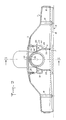
- the conduit 6 has at its base a rectangular section connected to the sleeve 5 by a vertical rear wall 20, by a vertical front wall 21 extended by an upper bend 22 (Figure 1) and by vertical side walls 23 extended by converging walls 24 connected at elbow 22 ( Figure 2).
- the duct 6 thus shaped connects the window 7 to the sleeve 5 with a progressive variation of the section and a guided deviation in the curve of the direction of flow.
- This conduit 6 is integral with the top 2 of the housing via a parallelepipedal bowl 25.
- the bottom 26 of the bowl is integral with the conduit 6, while the peripheral wall 27 of this bowl which is spaced from this conduit 6 is secured to the top 2 of the housing as well as to the upper half of the sleeve 5.
- the peripheral wall 27 delimits in the top 2 an opening 28 through which a part of the mold can pass, defining the shape of the upper outer portion of the sleeve 5 and of the conduit 6 as well as the interior shape of the bowl 25. It is provided to close the opening 28 by means of a cover 29 positioned in a recess of the top 2 and fixing, in a removable manner, by means of flexible tongues with teeth 30 clipped into slots 31 of the bowl 25.
- the cover 29 is integral with a lug 32 delimiting a semi-circular recess 33 whose diameter is substantially equal to the diameter of the bottom of the groove 19 of the end piece 13 of the tubing 11. Furthermore, a notch 34 is formed in the sleeve 5 and delimited by a sloping rear edge 36 which diverges upwards.
- the tab 32 of the cover 29 placed, enters the groove 19 of the 'end piece 13 and immobilizes, by abutment against the rear edge 37 of said groove, in translation said end piece without opposing its rotation.
- the tab 32 is integral with inclined ramps 38 cooperating with the sloping rear edges 36 of the notches 34 of the sleeve 5.
- the front edges 35 of the notches can be aligned with the front edge 37 of the groove 19 of the end piece 13 when the latter is in place so that the tab 32 and its ramps 38 get stuck perfectly in said notches.
- a metal strip 39 is shaped like the tab 32 at least for the part of the latter which penetrates into the groove 19 of the end piece 13. This strip is then interposed between the tab 32 and the posterior edge 37 of said groove. It ensures better sliding during rotation of the nozzle and reduces wear.
Landscapes
- Engineering & Computer Science (AREA)
- Mechanical Engineering (AREA)
- Electric Vacuum Cleaner (AREA)
- Electric Suction Cleaners (AREA)
- Centrifugal Separators (AREA)
- Quick-Acting Or Multi-Walled Pipe Joints (AREA)
Applications Claiming Priority (2)
| Application Number | Priority Date | Filing Date | Title |
|---|---|---|---|
| FR8914305 | 1989-10-31 | ||
| FR8914305A FR2653654B1 (fr) | 1989-10-31 | 1989-10-31 | Boitier a raccord tournant pour suceur d'aspirateur. |
Related Child Applications (3)
| Application Number | Title | Priority Date | Filing Date |
|---|---|---|---|
| EP19910400244 Division-Into EP0432149B1 (de) | 1989-10-31 | 1990-10-25 | Gehäuse mit Drehgelenk für Staubsaugermundstück |
| EP19910400244 Division EP0432149B1 (de) | 1989-10-31 | 1990-10-25 | Gehäuse mit Drehgelenk für Staubsaugermundstück |
| EP91400244.9 Division-Into | 1990-10-25 |
Publications (2)
| Publication Number | Publication Date |
|---|---|
| EP0426534A1 true EP0426534A1 (de) | 1991-05-08 |
| EP0426534B1 EP0426534B1 (de) | 1994-05-18 |
Family
ID=9386985
Family Applications (2)
| Application Number | Title | Priority Date | Filing Date |
|---|---|---|---|
| EP19900403008 Expired - Lifetime EP0426534B1 (de) | 1989-10-31 | 1990-10-25 | Gehäuse mit Drehgelenk für Staubsaugermundstück |
| EP19910400244 Expired - Lifetime EP0432149B1 (de) | 1989-10-31 | 1990-10-25 | Gehäuse mit Drehgelenk für Staubsaugermundstück |
Family Applications After (1)
| Application Number | Title | Priority Date | Filing Date |
|---|---|---|---|
| EP19910400244 Expired - Lifetime EP0432149B1 (de) | 1989-10-31 | 1990-10-25 | Gehäuse mit Drehgelenk für Staubsaugermundstück |
Country Status (4)
| Country | Link |
|---|---|
| EP (2) | EP0426534B1 (de) |
| DE (2) | DE69007758T2 (de) |
| ES (2) | ES2054448T3 (de) |
| FR (1) | FR2653654B1 (de) |
Cited By (4)
| Publication number | Priority date | Publication date | Assignee | Title |
|---|---|---|---|---|
| WO1994017720A1 (en) * | 1993-02-13 | 1994-08-18 | Vax Limited | Swivel joints primarily for mounting suction cleaner heads |
| EP0749719A2 (de) * | 1995-06-22 | 1996-12-27 | Siemens Aktiengesellschaft | Lösbare Anordnung eines Funktionsteiles in einer Gehäuseöffnung eines Staubsaugers |
| FR2748196A1 (fr) * | 1996-05-01 | 1997-11-07 | Wessel Werk Gmbh | Tete d'aspiration pour aspirateur |
| GB2422092A (en) * | 2005-01-18 | 2006-07-19 | Dyson Technology Ltd | Cleaning head for a vacuum cleaner |
Families Citing this family (2)
| Publication number | Priority date | Publication date | Assignee | Title |
|---|---|---|---|---|
| DE19839865A1 (de) * | 1998-09-02 | 2000-03-09 | Vorwerk Co Interholding | Staubsauger |
| DE102015104436A1 (de) * | 2015-03-24 | 2016-09-29 | Wessel-Werk Gmbh | Gleitsohle für eine Staubsaugerdüse |
Citations (4)
| Publication number | Priority date | Publication date | Assignee | Title |
|---|---|---|---|---|
| US2496813A (en) * | 1945-08-21 | 1950-02-07 | Electrolux Corp | Pipe joint |
| US2842794A (en) * | 1954-11-12 | 1958-07-15 | Electrolux Corp | Tapered multi-purpose nozzle |
| FR2535963A1 (fr) * | 1982-11-12 | 1984-05-18 | Olivier Ets Georges | Dispositif de montage tournant d'une tubulure aspirante sur un suceur d'aspirateur |
| DE3708503A1 (de) * | 1986-04-01 | 1987-10-08 | Siemens Ag | Staubsaugermundstueck |
Family Cites Families (2)
| Publication number | Priority date | Publication date | Assignee | Title |
|---|---|---|---|---|
| US3117338A (en) * | 1956-06-11 | 1964-01-14 | Filtex Corp | Suction nozzle |
| FR2599236B1 (fr) * | 1986-05-30 | 1989-03-10 | Olivier Ets Georges | Suceur d'aspirateur avec arrache-fils. |
-
1989
- 1989-10-31 FR FR8914305A patent/FR2653654B1/fr not_active Expired - Lifetime
-
1990
- 1990-10-25 ES ES91400244T patent/ES2054448T3/es not_active Expired - Lifetime
- 1990-10-25 DE DE1990607758 patent/DE69007758T2/de not_active Expired - Fee Related
- 1990-10-25 DE DE1990609004 patent/DE69009004T2/de not_active Expired - Fee Related
- 1990-10-25 EP EP19900403008 patent/EP0426534B1/de not_active Expired - Lifetime
- 1990-10-25 ES ES90403008T patent/ES2056418T3/es not_active Expired - Lifetime
- 1990-10-25 EP EP19910400244 patent/EP0432149B1/de not_active Expired - Lifetime
Patent Citations (4)
| Publication number | Priority date | Publication date | Assignee | Title |
|---|---|---|---|---|
| US2496813A (en) * | 1945-08-21 | 1950-02-07 | Electrolux Corp | Pipe joint |
| US2842794A (en) * | 1954-11-12 | 1958-07-15 | Electrolux Corp | Tapered multi-purpose nozzle |
| FR2535963A1 (fr) * | 1982-11-12 | 1984-05-18 | Olivier Ets Georges | Dispositif de montage tournant d'une tubulure aspirante sur un suceur d'aspirateur |
| DE3708503A1 (de) * | 1986-04-01 | 1987-10-08 | Siemens Ag | Staubsaugermundstueck |
Cited By (6)
| Publication number | Priority date | Publication date | Assignee | Title |
|---|---|---|---|---|
| WO1994017720A1 (en) * | 1993-02-13 | 1994-08-18 | Vax Limited | Swivel joints primarily for mounting suction cleaner heads |
| EP0749719A2 (de) * | 1995-06-22 | 1996-12-27 | Siemens Aktiengesellschaft | Lösbare Anordnung eines Funktionsteiles in einer Gehäuseöffnung eines Staubsaugers |
| EP0749719A3 (de) * | 1995-06-22 | 1998-06-03 | Bosch-Siemens Hausgeräte GmbH | Lösbare Anordnung eines Funktionsteiles in einer Gehäuseöffnung eines Staubsaugers |
| FR2748196A1 (fr) * | 1996-05-01 | 1997-11-07 | Wessel Werk Gmbh | Tete d'aspiration pour aspirateur |
| GB2422092A (en) * | 2005-01-18 | 2006-07-19 | Dyson Technology Ltd | Cleaning head for a vacuum cleaner |
| US9204770B2 (en) | 2005-01-18 | 2015-12-08 | Dyson Technology Limited | Cleaner head for a cleaning appliance |
Also Published As
| Publication number | Publication date |
|---|---|
| EP0432149A2 (de) | 1991-06-12 |
| ES2056418T3 (es) | 1994-10-01 |
| DE69007758D1 (de) | 1994-05-05 |
| FR2653654B1 (fr) | 1992-02-14 |
| ES2054448T3 (es) | 1994-08-01 |
| EP0426534B1 (de) | 1994-05-18 |
| FR2653654A1 (fr) | 1991-05-03 |
| DE69009004T2 (de) | 1994-10-13 |
| EP0432149B1 (de) | 1994-03-30 |
| DE69009004D1 (de) | 1994-06-23 |
| DE69007758T2 (de) | 1994-11-03 |
| EP0432149A3 (en) | 1991-08-21 |
Similar Documents
| Publication | Publication Date | Title |
|---|---|---|
| EP1671705B1 (de) | Mit einer Pumpe ausgestatteter Kunststoffspender | |
| EP1595771B1 (de) | Absperrventil für den Wasserkasten eines Kraftfahrzeuges, und solch ein Wasserkasten | |
| FR2669710A1 (fr) | Accouplement pour flexible, muni d'une piece tubulaire d'accouplement. | |
| FR2833686A1 (fr) | Raccord de cartouche de gaz comprime et d'appareil de fixation | |
| EP0426534B1 (de) | Gehäuse mit Drehgelenk für Staubsaugermundstück | |
| EP1330314A1 (de) | Fluidspender | |
| EP0499754B1 (de) | Verschluss zum dichten Befestigen eines elektrischen Kabels in einer Öffnung und Kabelschutzmuffe mit solchen Verschlüssen | |
| FR2712795A1 (fr) | Appareil d'entretien de sol, en particulier aspirateur-balai, muni de brosses disposées de préférence sur les bords extérieurs et dirigées vers le bas. | |
| FR2462554A1 (fr) | Couple de tuyaux d'echappement emboitables destines notamment aux tracteurs agricoles | |
| FR2754037A1 (fr) | Dispositif de raccordement etanche de deux tubes metalliques bout a bout | |
| FR2498729A1 (fr) | Raccord pour tuyaux | |
| EP0327441B1 (de) | Wärmetauscher | |
| WO2007017560A1 (fr) | Dispositif dεtancheite de connecteur | |
| FR2585444A3 (fr) | Raccord pour tuyau | |
| EP0327442B1 (de) | Verbindung zwischen einem Wärmeaustauscher und einem Rohrende | |
| EP3626143B1 (de) | Ansaugvorrichtung für haushaltssauger | |
| EP1467842B1 (de) | Druckgaspatrone für befestigungsvorrichtung mit integriertem dichtungsanschluss | |
| BE1018968A3 (fr) | Ensemble d'un couvercle et d'un organe de liaison destine a faire partie d'un pistolet a fluide. | |
| EP0863299B1 (de) | Thermostatventil zum Schnelleinbau | |
| FR2605030A1 (fr) | Systeme de montage d'une douchette sur le cote d'une baignoire. | |
| EP0579539B1 (de) | Ansaugvorrichtung für Kraftstoffbehälter | |
| FR2790936A1 (fr) | Suceur d'aspirateur commutable sur plusieurs fonctions d'aspiration | |
| FR2584918A3 (fr) | Dispositif d'accouplement d'une piece a main dentaire avec une piece motrice | |
| CA2620705A1 (fr) | Dispositif de raccordement de tuyaux pour un systeme d'aspiration | |
| FR2847792A1 (fr) | Dispositif de succion pour aspirateur |
Legal Events
| Date | Code | Title | Description |
|---|---|---|---|
| PUAI | Public reference made under article 153(3) epc to a published international application that has entered the european phase |
Free format text: ORIGINAL CODE: 0009012 |
|
| AK | Designated contracting states |
Kind code of ref document: A1 Designated state(s): CH DE ES FR GB IT LI SE |
|
| XX | Miscellaneous (additional remarks) |
Free format text: TEILANMELDUNG 91400244.9 EINGEREICHT AM 25/10/90. |
|
| 17P | Request for examination filed |
Effective date: 19911025 |
|
| 17Q | First examination report despatched |
Effective date: 19921124 |
|
| RAP1 | Party data changed (applicant data changed or rights of an application transferred) |
Owner name: ETABLISSEMENTS GEORGES OLIVIER SOCIETE ANONYME DIT |
|
| GRAA | (expected) grant |
Free format text: ORIGINAL CODE: 0009210 |
|
| AK | Designated contracting states |
Kind code of ref document: B1 Designated state(s): CH DE ES FR GB IT LI SE |
|
| XX | Miscellaneous (additional remarks) |
Free format text: TEILANMELDUNG 91400244.9 EINGEREICHT AM 25/10/90. |
|
| REF | Corresponds to: |
Ref document number: 69009004 Country of ref document: DE Date of ref document: 19940623 |
|
| GBT | Gb: translation of ep patent filed (gb section 77(6)(a)/1977) |
Effective date: 19940622 |
|
| ITF | It: translation for a ep patent filed | ||
| REG | Reference to a national code |
Ref country code: ES Ref legal event code: FG2A Ref document number: 2056418 Country of ref document: ES Kind code of ref document: T3 |
|
| PGFP | Annual fee paid to national office [announced via postgrant information from national office to epo] |
Ref country code: ES Payment date: 19941014 Year of fee payment: 5 |
|
| PGFP | Annual fee paid to national office [announced via postgrant information from national office to epo] |
Ref country code: SE Payment date: 19941018 Year of fee payment: 5 Ref country code: CH Payment date: 19941018 Year of fee payment: 5 |
|
| EAL | Se: european patent in force in sweden |
Ref document number: 90403008.7 |
|
| PLBE | No opposition filed within time limit |
Free format text: ORIGINAL CODE: 0009261 |
|
| STAA | Information on the status of an ep patent application or granted ep patent |
Free format text: STATUS: NO OPPOSITION FILED WITHIN TIME LIMIT |
|
| 26N | No opposition filed | ||
| PG25 | Lapsed in a contracting state [announced via postgrant information from national office to epo] |
Ref country code: SE Effective date: 19951026 Ref country code: ES Free format text: LAPSE BECAUSE OF THE APPLICANT RENOUNCES Effective date: 19951026 |
|
| PG25 | Lapsed in a contracting state [announced via postgrant information from national office to epo] |
Ref country code: LI Effective date: 19951031 Ref country code: CH Effective date: 19951031 |
|
| REG | Reference to a national code |
Ref country code: CH Ref legal event code: PL |
|
| EUG | Se: european patent has lapsed |
Ref document number: 90403008.7 |
|
| PGFP | Annual fee paid to national office [announced via postgrant information from national office to epo] |
Ref country code: DE Payment date: 19981014 Year of fee payment: 9 |
|
| PGFP | Annual fee paid to national office [announced via postgrant information from national office to epo] |
Ref country code: GB Payment date: 19981020 Year of fee payment: 9 |
|
| PGFP | Annual fee paid to national office [announced via postgrant information from national office to epo] |
Ref country code: FR Payment date: 19981030 Year of fee payment: 9 |
|
| PG25 | Lapsed in a contracting state [announced via postgrant information from national office to epo] |
Ref country code: GB Free format text: LAPSE BECAUSE OF NON-PAYMENT OF DUE FEES Effective date: 19991025 |
|
| REG | Reference to a national code |
Ref country code: ES Ref legal event code: FD2A Effective date: 19991007 |
|
| GBPC | Gb: european patent ceased through non-payment of renewal fee |
Effective date: 19991025 |
|
| PG25 | Lapsed in a contracting state [announced via postgrant information from national office to epo] |
Ref country code: FR Free format text: LAPSE BECAUSE OF NON-PAYMENT OF DUE FEES Effective date: 20000630 |
|
| PG25 | Lapsed in a contracting state [announced via postgrant information from national office to epo] |
Ref country code: DE Free format text: LAPSE BECAUSE OF NON-PAYMENT OF DUE FEES Effective date: 20000801 |
|
| REG | Reference to a national code |
Ref country code: FR Ref legal event code: ST |
|
| PG25 | Lapsed in a contracting state [announced via postgrant information from national office to epo] |
Ref country code: IT Free format text: LAPSE BECAUSE OF NON-PAYMENT OF DUE FEES Effective date: 20051025 |