EP0426534A1 - Housing with swivel connection for vacuum cleaner nozzle - Google Patents
Housing with swivel connection for vacuum cleaner nozzle Download PDFInfo
- Publication number
- EP0426534A1 EP0426534A1 EP90403008A EP90403008A EP0426534A1 EP 0426534 A1 EP0426534 A1 EP 0426534A1 EP 90403008 A EP90403008 A EP 90403008A EP 90403008 A EP90403008 A EP 90403008A EP 0426534 A1 EP0426534 A1 EP 0426534A1
- Authority
- EP
- European Patent Office
- Prior art keywords
- sleeve
- groove
- housing
- tubing
- notch
- Prior art date
- Legal status (The legal status is an assumption and is not a legal conclusion. Google has not performed a legal analysis and makes no representation as to the accuracy of the status listed.)
- Granted
Links
- 238000002347 injection Methods 0.000 claims description 5
- 239000007924 injection Substances 0.000 claims description 5
- 239000002184 metal Substances 0.000 claims description 3
- 238000000465 moulding Methods 0.000 description 6
- 230000001627 detrimental effect Effects 0.000 description 3
- 230000002093 peripheral effect Effects 0.000 description 3
- 230000006866 deterioration Effects 0.000 description 2
- 238000007789 sealing Methods 0.000 description 2
- 230000008878 coupling Effects 0.000 description 1
- 238000010168 coupling process Methods 0.000 description 1
- 238000005859 coupling reaction Methods 0.000 description 1
- 230000007547 defect Effects 0.000 description 1
- 230000002950 deficient Effects 0.000 description 1
- 230000008021 deposition Effects 0.000 description 1
- 239000000428 dust Substances 0.000 description 1
- 239000000835 fiber Substances 0.000 description 1
- 238000012423 maintenance Methods 0.000 description 1
- 239000002991 molded plastic Substances 0.000 description 1
- 239000002245 particle Substances 0.000 description 1
- 230000000750 progressive effect Effects 0.000 description 1
- 210000002105 tongue Anatomy 0.000 description 1
- XLYOFNOQVPJJNP-UHFFFAOYSA-N water Substances O XLYOFNOQVPJJNP-UHFFFAOYSA-N 0.000 description 1
Images


Classifications
-
- A—HUMAN NECESSITIES
- A47—FURNITURE; DOMESTIC ARTICLES OR APPLIANCES; COFFEE MILLS; SPICE MILLS; SUCTION CLEANERS IN GENERAL
- A47L—DOMESTIC WASHING OR CLEANING; SUCTION CLEANERS IN GENERAL
- A47L9/00—Details or accessories of suction cleaners, e.g. mechanical means for controlling the suction or for effecting pulsating action; Storing devices specially adapted to suction cleaners or parts thereof; Carrying-vehicles specially adapted for suction cleaners
- A47L9/02—Nozzles
Definitions
- the present invention relates to improvements made to housings with a rotary coupling for a vacuum cleaner nozzle.
- a rotary connector housing for a vacuum cleaner nozzle generally has a top and a side wall, the rear part of which forms a body. This sleeve opening to the outside is intended to receive a tubing of a connector rigidly connected or articulated on a tubular handle of a vacuum cleaner.
- the connection tubing is mounted to rotate about an anteroposterior axis and immobilized in translation in the sleeve.
- the top of the housing forms a body with a substantially vertical internal conduit, communicating the aforementioned connection tubing with a window of a slip sole fitted and fixed under the housing, window which opens into a longitudinal channel suction from the sole.
- a first known type of rotary mounting of the tubing consists in providing a molding opening in the tubing near its free end, a groove opening on the outside and in the sleeve near the duct, a groove opening on the inside, placing these two grooves facing each other when a shoulder of the tubing abuts against the free end of the sleeve and to accommodate in these grooves an elastically deformable split ring.
- This ring usually called a circlip ensures the non-removable connection of the tubing with the sleeve, a connection which allows it to rotate but not to disengage.
- the drawback of this first type of mounting is that the thickness of the sleeve is not constant and that this results in molding difficulties, shrinkage detrimental to the aesthetics of the finished part and a lowering of the rate d 'injection. Furthermore, the tubing is non-removable, which can be detrimental to good maintenance of the nozzle.
- a second known type of rotary mounting of the tubing consists in engaging two parallel rods in the sleeve so that they penetrate tangentially into the groove of the tubing.
- the molding reveals marks due to shrinkage, marks that compromise aesthetics.
- the molding is in this case improved. Disassembly although difficult becomes possible but is often accompanied by deterioration. By cons, the guide is defective and gives rise very quickly to a game detrimental to the operation of the squeegee.
- the object of the present invention is to remedy these drawbacks: by proposing a rotary mounting means such that the thickness of the sleeve is constant, that the guidance of the tubing is practically perfect and that the disassembly of said tubing is easily and without deterioration possible, - and by concomitantly providing the means necessary to ensure a better flow of the gas flow and to reduce the risks of deposition of particles (dust, fibers, hair, etc.) in the nozzle and of leakage outside, at the same time as these means facilitate molding, increase the injection rate and therefore reduce the cost price, eliminate apparent defects: shrinkage, injection point ...
- the sleeve is free from a groove, has a substantially constant thickness and delimits a notch extending substantially over the upper half of its periphery opposite an opening made in the top of the housing
- the tubing has a cylindrical seat rotatably mounted in the sleeve and limited by a butting shoulder against the free end of the latter, position in which a groove of this tube is located opposite the aforementioned notch of the sleeve
- a tab delimits a semicircular recess with a diameter at least equal as close as possible to the diameter at the bottom of the throat of the tubing, is capable of passing through the notch of the sleeve to penetrate the throat and is integral with a clip-on cover normally fitted in the aforementioned opening of the housing, position in which the tubing is immobilized in translation on the outside by abutment of its shoulder against the free end of the sleeve and on the inside by abutment of the front edge
- the rear edge of the notch of the sleeve is in a divergent upward slope to cooperate with inclined lateral ramps of the tab intended to position the tubing axially in said sleeve; the front edge of the throat of the tubing is located opposite the front edge of the notch of the sleeve.
- a metal strip having substantially the shape of the tab can be interposed between it and the front edge of the groove of the tube.
- the housing comprising a vertical internal conduit which opens at the top into the sleeve and at the bottom in a window of a sole normally fixed under this housing, according to the invention, the conduit is bent in top towards the sleeve to reduce pressure losses, the opening of the top of the housing normally closed by the cover of the aforementioned tab having a width determined in correspondence with the anteroposterior extent of the elbow to allow the passage of the part of the mold which defines the upper external shape of the elbow, as well as of the injection nozzle.
- the squeegee comprises a casing 1 made of molded plastic.
- the housing has a top 2 forming a body: - with a peripheral wall 3, the rear part 4 of which has an internal and external projection, a tubular sleeve 5, - And with a vertical duct 6 which opens at the top into the sleeve 5 and at the bottom in a window 7 of a longitudinal suction channel 8 formed in a sole 9 fixed to candles 10 of this housing.
- a suction pipe 11 can be connected by its bent end 12 to a vacuum cleaner handle. Its free end 13 forms a tubular end piece which projects from a shoulder 14.
- the end piece 13 has cylindrical bearing surfaces 15 to 17 intended to be fitted into the sleeve 5. Between the bearing surfaces 15 and 16 are provided annular sealing lips 18 and an axial immobilization groove 19 separates the bearing surfaces 16 and 17.
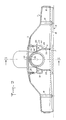
- the conduit 6 has at its base a rectangular section connected to the sleeve 5 by a vertical rear wall 20, by a vertical front wall 21 extended by an upper bend 22 (Figure 1) and by vertical side walls 23 extended by converging walls 24 connected at elbow 22 ( Figure 2).
- the duct 6 thus shaped connects the window 7 to the sleeve 5 with a progressive variation of the section and a guided deviation in the curve of the direction of flow.
- This conduit 6 is integral with the top 2 of the housing via a parallelepipedal bowl 25.
- the bottom 26 of the bowl is integral with the conduit 6, while the peripheral wall 27 of this bowl which is spaced from this conduit 6 is secured to the top 2 of the housing as well as to the upper half of the sleeve 5.
- the peripheral wall 27 delimits in the top 2 an opening 28 through which a part of the mold can pass, defining the shape of the upper outer portion of the sleeve 5 and of the conduit 6 as well as the interior shape of the bowl 25. It is provided to close the opening 28 by means of a cover 29 positioned in a recess of the top 2 and fixing, in a removable manner, by means of flexible tongues with teeth 30 clipped into slots 31 of the bowl 25.
- the cover 29 is integral with a lug 32 delimiting a semi-circular recess 33 whose diameter is substantially equal to the diameter of the bottom of the groove 19 of the end piece 13 of the tubing 11. Furthermore, a notch 34 is formed in the sleeve 5 and delimited by a sloping rear edge 36 which diverges upwards.
- the tab 32 of the cover 29 placed, enters the groove 19 of the 'end piece 13 and immobilizes, by abutment against the rear edge 37 of said groove, in translation said end piece without opposing its rotation.
- the tab 32 is integral with inclined ramps 38 cooperating with the sloping rear edges 36 of the notches 34 of the sleeve 5.
- the front edges 35 of the notches can be aligned with the front edge 37 of the groove 19 of the end piece 13 when the latter is in place so that the tab 32 and its ramps 38 get stuck perfectly in said notches.
- a metal strip 39 is shaped like the tab 32 at least for the part of the latter which penetrates into the groove 19 of the end piece 13. This strip is then interposed between the tab 32 and the posterior edge 37 of said groove. It ensures better sliding during rotation of the nozzle and reduces wear.
Landscapes
- Engineering & Computer Science (AREA)
- Mechanical Engineering (AREA)
- Electric Vacuum Cleaner (AREA)
- Centrifugal Separators (AREA)
- Electric Suction Cleaners (AREA)
- Quick-Acting Or Multi-Walled Pipe Joints (AREA)
Abstract
Description
La présente invention concerne des perfectionnements apportés aux boîtiers à raccord tournant pour suceur d'aspirateur.The present invention relates to improvements made to housings with a rotary coupling for a vacuum cleaner nozzle.
Un boîtier à raccord tournant pour suceur d'aspirateur comporte généralement un dessus et une paroi latérale dont la partie postérieure fait corps avec un manchon. Ce manchon débouchant à l'extérieur est destiné à recevoir une tubulure d'un raccord branché rigidement ou de façon articulée sur un manche tubulaire d'aspirateur. La tubulure du raccord est montée tournante autour d'un axe antéro-postérieur et immobilisée en translation dans le manchon.A rotary connector housing for a vacuum cleaner nozzle generally has a top and a side wall, the rear part of which forms a body. This sleeve opening to the outside is intended to receive a tubing of a connector rigidly connected or articulated on a tubular handle of a vacuum cleaner. The connection tubing is mounted to rotate about an anteroposterior axis and immobilized in translation in the sleeve.
Le dessus du boîtier fait corps avec un conduit interne sensiblement vertical, faisant communiquer la tubulure de raccordement précitée avec une fenêtre d'une semelle de glissement rapportée et fixée sous le boîtier, fenêtre qui débouche dans un canal longitudinal aspirant de la semelle.The top of the housing forms a body with a substantially vertical internal conduit, communicating the aforementioned connection tubing with a window of a slip sole fitted and fixed under the housing, window which opens into a longitudinal channel suction from the sole.
Un premier type connu de montage tournant de la tubulure consiste à ménager de moulage dans la tubulure près de son extrémité libre une gorge débouchant à l'extérieur et dans le manchon près du conduit une gorge débouchant à l'intérieur, à disposer ces deux gorges en regard l'une de l'autre lorsqu'un épaulement de la tubulure bute contre l'extrémité libre du manchon et à loger dans ces gorges un anneau fendu déformable élastiquement. Cet anneau dénommé habituellement circlip assure la liaison indémontable de la tubulure avec le manchon, liaison qui permet de tourner mais non de se déboîter.A first known type of rotary mounting of the tubing consists in providing a molding opening in the tubing near its free end, a groove opening on the outside and in the sleeve near the duct, a groove opening on the inside, placing these two grooves facing each other when a shoulder of the tubing abuts against the free end of the sleeve and to accommodate in these grooves an elastically deformable split ring. This ring usually called a circlip ensures the non-removable connection of the tubing with the sleeve, a connection which allows it to rotate but not to disengage.
L'inconvénient de ce premier type de montage est que l'épaisseur du manchon n'est pas constante et qu'il en résulte des difficultés de moulage, des retassures nuisant à l'esthétique de la pièce finie et un abaissement de la cadence d'injection. Par ailleurs, la tubulure est indémontable, ce qui peut être préjudiciable à un bon entretien du suceur.The drawback of this first type of mounting is that the thickness of the sleeve is not constant and that this results in molding difficulties, shrinkage detrimental to the aesthetics of the finished part and a lowering of the rate d 'injection. Furthermore, the tubing is non-removable, which can be detrimental to good maintenance of the nozzle.
Un deuxième type connu de montage tournant de la tubulure consiste à engager deux tiges parallèles dans le manchon afin qu'elles pénètrent tangentiellement dans la gorge de la tubulure.A second known type of rotary mounting of the tubing consists in engaging two parallel rods in the sleeve so that they penetrate tangentially into the groove of the tubing.
Par ailleurs, le moulage laisse apparaître des marques dues aux retassures, marques qui compromettent l'esthétique.Furthermore, the molding reveals marks due to shrinkage, marks that compromise aesthetics.
Le moulage se trouve dans ce cas amélioré. Le démontage bien que difficile devient possible mais s'accompagne souvent de détériorations. Par contre, le guidage est défectueux et donne naissance très rapidement à un jeu nuisant à la manoeuvre du suceur.The molding is in this case improved. Disassembly although difficult becomes possible but is often accompanied by deterioration. By cons, the guide is defective and gives rise very quickly to a game detrimental to the operation of the squeegee.
Indépendamment du montage tournant de la tubulure se posent, le problème de l'amélioration de l'écoulement du flux gazeux et le problème de l'étanchéité du montage à l'air et à l'eau. En effet, lorsque le suceur est utilisé sur des sols mouillés, il "bave" au niveau du joint tournant de la tubulure connue, ce qui, d'une part, est salissant, d'autre part, compromet l'efficacité de l'aspiration, enfin, nuit à l'image de qualité auprès de la clientèle, sachant que cette amélioration ne doit pas s'accompagner d'une difficulté de moulage.Regardless of the rotating assembly of the tubing arise, the problem of improving the flow of the gas flow and the problem of sealing the assembly with air and water. Indeed, when the nozzle is used on wet floors, it "drools" at the rotating joint of the known tubing, which, on the one hand, is dirty, on the other hand, compromises the effectiveness of the aspiration, finally, harms the image of quality with customers, knowing that this improvement should not be accompanied by a difficulty in molding.
La présente invention a pour but de remédier à ces inconvénients:
- en proposant un moyen de montage tournant tel que l'épaisseur du manchon est constante, que le guidage de la tubulure est pratiquement parfait et que le démontage de ladite tubulure est faisable facilement et sans détérioration,
- et en apportant concomitamment les moyens nécessaires à assurer un meilleur écoulement du flux gazeux et à réduire les risques de dépôt des particules (poussières, fibres, cheveux...) dans le suceur et de fuite à l'extérieur, en même temps que ces moyens permettent de faciliter le moulage, d'accroître la cadence d'injection et donc de diminuer le prix de revient, d'éliminer les défauts apparents : retassures, point d'injection...The object of the present invention is to remedy these drawbacks:
by proposing a rotary mounting means such that the thickness of the sleeve is constant, that the guidance of the tubing is practically perfect and that the disassembly of said tubing is easily and without deterioration possible,
- and by concomitantly providing the means necessary to ensure a better flow of the gas flow and to reduce the risks of deposition of particles (dust, fibers, hair, etc.) in the nozzle and of leakage outside, at the same time as these means facilitate molding, increase the injection rate and therefore reduce the cost price, eliminate apparent defects: shrinkage, injection point ...
Dans ce but et conformément à l'invention :
- le manchon est exempt de gorge, présente une épaisseur sensiblement constante et délimite une encoche s'étendant sensiblement sur la moitié supérieure de sa périphérie en regard d'une ouverture ménagée dans le dessus du boîtier,
- la tubulure comporte une portée cylindrique montée tournante dans le manchon et limitée par un épaulement butant contre l'extrémité libre de celui-ci, position dans laquelle une gorge de cette tubulure est située en regard de l'encoche précitée du manchon,
- une patte délimite un évidement semi-circulaire de diamètre au moins égal au plus près au diamètre à fond de gorge de la tubulure, est susceptible de traverser l'encoche du manchon pour pénétrer dans la gorge et fait corps avec un couvercle clipsable normalement emboîté dans l'ouverture précitée du boîtier, position dans laquelle la tubulure est immobilisée en translation à l'extérieur par butée de son épaulement contre l'extrémité libre du manchon et à l'intérieur par butée du chant antérieur de sa gorge contre le bord semi-circulaire supérieur de l'évidement de la patte rapportée.For this purpose and in accordance with the invention:
the sleeve is free from a groove, has a substantially constant thickness and delimits a notch extending substantially over the upper half of its periphery opposite an opening made in the top of the housing,
- the tubing has a cylindrical seat rotatably mounted in the sleeve and limited by a butting shoulder against the free end of the latter, position in which a groove of this tube is located opposite the aforementioned notch of the sleeve,
- a tab delimits a semicircular recess with a diameter at least equal as close as possible to the diameter at the bottom of the throat of the tubing, is capable of passing through the notch of the sleeve to penetrate the throat and is integral with a clip-on cover normally fitted in the aforementioned opening of the housing, position in which the tubing is immobilized in translation on the outside by abutment of its shoulder against the free end of the sleeve and on the inside by abutment of the front edge of its groove against the semi edge -circular upper of the recess of the attached leg.
Suivant une forme de réalisation particulièrement avantageuse, le bord postérieur de l'encoche du manchon est en pente divergente vers le haut pour coopérer avec des rampes inclinées latérales de la patte destinées à positionner axialement la tubulure dans ledit manchon ; le chant antérieur de la gorge de la tubulure est situé en regard du bord antérieur de l'encoche du manchon.According to a particularly advantageous embodiment, the rear edge of the notch of the sleeve is in a divergent upward slope to cooperate with inclined lateral ramps of the tab intended to position the tubing axially in said sleeve; the front edge of the throat of the tubing is located opposite the front edge of the notch of the sleeve.
Pour mieux résister à l'usure, un feuillard métallique ayant sensiblement la forme de la patte peut être interposé entre elle-ci et le chant antérieur de la gorge de la tubulure.To better resist wear, a metal strip having substantially the shape of the tab can be interposed between it and the front edge of the groove of the tube.
En ce qui concerne plus spécialement le boîtier, celui-ci comportant un conduit interne vertical qui débouche en haut dans le manchon et en bas dans une fenêtre d'une semelle normalement fixée sous ce boîtier, selon l'invention, le conduit est coudé en haut vers le manchon pour diminuer les pertes de charge, l'ouverture du dessus du boîtier normalement obturée par le couvercle de la patte précitée ayant une largeur déterminée en correspondance avec l'étendue antéro-postérieure du coude pour permettre le passage de la partie du moule qui définit la forme extérieure supérieure du coude, ainsi que de la buse d'injection.As regards more specifically the housing, the latter comprising a vertical internal conduit which opens at the top into the sleeve and at the bottom in a window of a sole normally fixed under this housing, according to the invention, the conduit is bent in top towards the sleeve to reduce pressure losses, the opening of the top of the housing normally closed by the cover of the aforementioned tab having a width determined in correspondence with the anteroposterior extent of the elbow to allow the passage of the part of the mold which defines the upper external shape of the elbow, as well as of the injection nozzle.
Divers autres caractéristiques et avantages de l'invention ressortent d'ailleurs de la description détaillée qui suit.Various other characteristics and advantages of the invention will also emerge from the detailed description which follows.
Une forme de réalisation de l'objet de l'invention et une variante sont représentées, à titre d'exemples non limitatifs, sur le dessin annexé.An embodiment of the object of the invention and a variant are shown, by way of nonlimiting examples, in the accompanying drawing.
Sur ce dessin :
- - la figure 1 est une coupe antéro-postérieure verticale d'un suceur conforme à l'invention, prise suivant la ligne I-I de la figure 2,
- - la figure 2 est une coupe transversale prise suivant la ligne II-II de la figure 1,
- - les figures 3 et 4 sont des vues analogues aux figures 1 et 2 respectivement, illustrant une variante de réalisation.
- FIG. 1 is a vertical anteroposterior section of a nozzle according to the invention, taken along line II of FIG. 2,
- FIG. 2 is a cross section taken on the line II-II in FIG. 1,
- - Figures 3 and 4 are views similar to Figures 1 and 2 respectively, illustrating an alternative embodiment.
Comme le montre le dessin, le suceur comporte un boîtier 1 en matière plastique moulée. Le boîtier présente un dessus 2 faisant corps :
- avec une paroi périphérique 3 dont la partie postérieure 4 présente en saillie interne et externe un manchon tubulaire 5,
- et avec un conduit vertical 6 qui débouche en haut dans le manchon 5 et en bas dans une fenêtre 7 d'un canal longitudinal d'aspiration 8 ménagé dans une semelle 9 fixée sur des chandelles 10 de ce boîtier.As shown in the drawing, the squeegee comprises a casing 1 made of molded plastic. The housing has a
- with a
- And with a
Une tubulure d'aspiration 11 est susceptible d'être raccordée par son extrémité coudée 12 à un manche d'aspirateur. Son extrémité libre 13 forme un embout tubulaire qui fait saillie sur un épaulement 14. L'embout 13 comporte des portées cylindriques 15 à 17 destinées à être emboîtées dans le manchon 5. Entre les portées 15 et 16 sont prévues des lèvres annulaires d'étanchéité 18 et une gorge d'immobilisation axiale 19 sépare les portées 16 et 17.A suction pipe 11 can be connected by its
Le conduit 6 présente à sa base une section rectangulaire raccordée au manchon 5 par une paroi postérieure verticale 20, par une paroi antérieure verticale 21 prolongée par un coude supérieur 22 (figure 1) et par des parois latérales verticales 23 prolongées par des parois convergentes 24 raccordées au coude 22 (figure 2).The
Le conduit 6 ainsi conformé relie la fenêtre 7 au manchon 5 avec une variation progressive de la section et une déviation guidée en courbe de la direction de l'écoulement. Ce conduit 6 fait corps avec le dessus 2 du boîtier par l'intermédiaire d'une cuvette parallélépipédique 25. Le fond 26 de la cuvette est solidaire du conduit 6, tandis que la paroi périphérique 27 de cette cuvette qui est écartée de ce conduit 6 est solidaire du dessus 2 du boîtier ainsi que de la moitié supérieure du manchon 5.The
La paroi périphérique 27 délimite dans le dessus 2 une ouverture 28 à travers laquelle peut passer une partie du moule, définissant la forme de la portion extérieure haute du manchon 5 et du conduit 6 ainsi que la forme intérieure de la cuvette 25. Il est prévu de fermer l'ouverture 28 au moyen d'un couvercle 29 se positionnant dans un embrèvement du dessus 2 et se fixant, de façon démontable, au moyen de languettes flexibles à dents 30 clipsées dans des lumières 31 de la cuvette 25.The
Le couvercle 29 fait corps avec une patte 32 délimitant un évidement semi-circulaire 33 dont le diamètre est sensiblement égal au diamètre du fond de la gorge 19 de l'embout 13 de la tubulure 11. Par ailleurs, une encoche 34 est ménagée dans le manchon 5 et délimitée par un bord postérieur pentu 36 qui diverge vers le haut.The
Lorsque l'embout 13 de la tubulure tournante 11 est emboîté dans le manchon 5 du boîtier et que son épaulement 14 bute contre l'extrémité extérieure libre de ce manchon 5, la patte 32 du couvercle 29 posé, pénètre dans la gorge 19 de l'embout 13 et immobilise, par butée contre le chant postérieur 37 de ladite gorge, en translation ledit embout sans s'opposer à sa rotation. Pour bien verrouiller cette immobilisation, la patte 32 fait corps avec des rampes inclinées 38 coopérant avec les bords postérieurs pentus 36 des encoches 34 du manchon 5. Avantageusement, les bords antérieurs 35 des encoches peuvent être alignés avec le chant antérieur 37 de la gorge 19 de l'embout 13 lorsque celui-ci est en place pour que la patte 32 et ses rampes 38 se coincent parfaitement dans lesdites encoches.When the
Bien entendu, pour assurer le montage tournant de la tubulure, il n'est nullement nécessaire de prévoir la cuvette 25 et un couvercle 29 aussi grand. En effet, la patte amovible 32 suffit. Mais dans ce cas, le haut du conduit 6 ne peut pas être coudé et s'étend jusqu'au-dessus 2 du boîtier.Of course, to ensure the rotary mounting of the tubing, there is no need to provide the
Suivant une variante illustrée par les figures 3 et 4, un feuillard métallique 39 est conformé comme la patte 32 tout au moins pour la partie de celle-ci qui pénètre dans la gorge 19 de l'embout 13. Ce feuillard est alors interposé entre la patte 32 et le chant postérieur 37 de ladite gorge. Il assure un meilleur glissement lors de la rotation de l'embout et réduit l'usure.According to a variant illustrated in FIGS. 3 and 4, a
Claims (5)
caractérisé en ce que:
- le manchon (5) est exempt de gorge, présente une épaisseur sensiblement constante et délimite une encoche (34) s'étendant sensiblement sur la moitié supérieure de sa périphérie en regard d'une ouverture (28) ménagée dans le dessus (2) du boîtier,
- la tubulure (11) comporte une portée cylindrique (15 à 17) montée tournante dans le manchon (5) et limitée par un épaulement (14) butant contre l'extrémité libre de celui-ci, position dans laquelle une gorge (19) de cette tubulure est située en regard de l'encoche précitée (34) du manchon,
- une patte (32) délimite un évidement semi-circulaire (33) de diamètre au moins égal au plus près au diamètre à fond de gorge de la tubulure, est susceptible de traverser l'encoche (34) du manchon pour pénétrer dans la gorge (19) et fait corps avec un couvercle clipsable (29) normalement emboîté dans l'ouverture (28) précitée du boîtier, position dans laquelle la tubulure (11) est immobilisée en translation à l'extérieur par butée de son épaulement (14) contre l'extrémité libre du manchon et à l'intérieur par butée du chant antérieur (37) de sa gorge (19) contre le bord semi-circulaire supérieur de l'évidement (33) de la patte rapportée (32).1.- Housing with rotating connector for vacuum cleaner nozzle, the rear wall (4) of which forms a body (5) intended to receive a tube (11) for connection to a vacuum cleaner, this tube being mounted to rotate and immobilized in translation in the sleeve,
characterized in that:
- the sleeve (5) is free from a groove, has a substantially constant thickness and delimits a notch (34) extending substantially over the upper half of its periphery opposite an opening (28) formed in the top (2) of the housing,
- the tubing (11) has a cylindrical surface (15 to 17) rotatably mounted in the sleeve (5) and limited by a shoulder (14) abutting against the free end thereof, position in which a groove (19) this tubing is located opposite the aforementioned notch (34) of the sleeve,
- A lug (32) delimits a semi-circular recess (33) of diameter at least equal as close as possible to the diameter at the bottom of the groove of the tube, is capable of passing through the notch (34) of the sleeve to penetrate into the groove (19) and is integral with a clip-on cover (29) normally fitted into the aforementioned opening (28) of the housing, position in which the tube (11) is immobilized in translation outside by abutment on its shoulder (14) against the free end of the sleeve and inside by abutment of the front edge (37) of its groove (19) against the upper semi-circular edge of the recess (33) of the attached tab (32).
caractérisé en ce que le conduit (6) est coudé en haut (22) vers le manchon (5) pour diminuer les pertes de charge, l'ouverture (28) du dessus (2) du boîtier normalement obturée par le couvercle (29) de la patte (32) précitée ayant une largeur déterminée en correspondance avec l'étendue antéro-postérieure du coude pour permettre le passage de la partie du moule qui définit la forme extérieure supérieure du coude, ainsi que de la buse d'injection.5.- Housing according to any one of claims 1 to 4, comprising a vertical internal conduit (6) which opens at the top in the sleeve (5) and at the bottom in a window (7) of a sole (9) normally fixed under this case,
characterized in that the duct (6) is bent at the top (22) towards the sleeve (5) to reduce the pressure losses, the opening (28) from above (2) of the housing normally closed by the cover (29) of the aforementioned tab (32) having a width determined in correspondence with the anteroposterior extent of the elbow to allow the passage of the part of the mold which defines the upper external shape of the elbow, as well as of the injection nozzle.
Applications Claiming Priority (2)
| Application Number | Priority Date | Filing Date | Title |
|---|---|---|---|
| FR8914305A FR2653654B1 (en) | 1989-10-31 | 1989-10-31 | ROTATING CONNECTION HOUSING FOR VACUUM CLEANER. |
| FR8914305 | 1989-10-31 |
Related Child Applications (3)
| Application Number | Title | Priority Date | Filing Date |
|---|---|---|---|
| EP91400244.9 Division-Into | 1990-10-25 | ||
| EP19910400244 Division-Into EP0432149B1 (en) | 1989-10-31 | 1990-10-25 | Housing with swirel connection for vacuum cleaner nozzle |
| EP19910400244 Division EP0432149B1 (en) | 1989-10-31 | 1990-10-25 | Housing with swirel connection for vacuum cleaner nozzle |
Publications (2)
| Publication Number | Publication Date |
|---|---|
| EP0426534A1 true EP0426534A1 (en) | 1991-05-08 |
| EP0426534B1 EP0426534B1 (en) | 1994-05-18 |
Family
ID=9386985
Family Applications (2)
| Application Number | Title | Priority Date | Filing Date |
|---|---|---|---|
| EP19910400244 Expired - Lifetime EP0432149B1 (en) | 1989-10-31 | 1990-10-25 | Housing with swirel connection for vacuum cleaner nozzle |
| EP19900403008 Expired - Lifetime EP0426534B1 (en) | 1989-10-31 | 1990-10-25 | Housing with swivel connection for vacuum cleaner nozzle |
Family Applications Before (1)
| Application Number | Title | Priority Date | Filing Date |
|---|---|---|---|
| EP19910400244 Expired - Lifetime EP0432149B1 (en) | 1989-10-31 | 1990-10-25 | Housing with swirel connection for vacuum cleaner nozzle |
Country Status (4)
| Country | Link |
|---|---|
| EP (2) | EP0432149B1 (en) |
| DE (2) | DE69009004T2 (en) |
| ES (2) | ES2056418T3 (en) |
| FR (1) | FR2653654B1 (en) |
Cited By (4)
| Publication number | Priority date | Publication date | Assignee | Title |
|---|---|---|---|---|
| WO1994017720A1 (en) * | 1993-02-13 | 1994-08-18 | Vax Limited | Swivel joints primarily for mounting suction cleaner heads |
| EP0749719A2 (en) * | 1995-06-22 | 1996-12-27 | Siemens Aktiengesellschaft | Detachable arrangement of a function element in an opening of a vacuum cleaner housing |
| FR2748196A1 (en) * | 1996-05-01 | 1997-11-07 | Wessel Werk Gmbh | SUCTION HEAD FOR VACUUM |
| GB2422092A (en) * | 2005-01-18 | 2006-07-19 | Dyson Technology Ltd | Cleaning head for a vacuum cleaner |
Families Citing this family (2)
| Publication number | Priority date | Publication date | Assignee | Title |
|---|---|---|---|---|
| DE19839865A1 (en) * | 1998-09-02 | 2000-03-09 | Vorwerk Co Interholding | vacuum cleaner |
| DE102015104436A1 (en) * | 2015-03-24 | 2016-09-29 | Wessel-Werk Gmbh | Sliding sole for a vacuum cleaner nozzle |
Citations (4)
| Publication number | Priority date | Publication date | Assignee | Title |
|---|---|---|---|---|
| US2496813A (en) * | 1945-08-21 | 1950-02-07 | Electrolux Corp | Pipe joint |
| US2842794A (en) * | 1954-11-12 | 1958-07-15 | Electrolux Corp | Tapered multi-purpose nozzle |
| FR2535963A1 (en) * | 1982-11-12 | 1984-05-18 | Olivier Ets Georges | Vacuum cleaner head suction hose coupling |
| DE3708503A1 (en) * | 1986-04-01 | 1987-10-08 | Siemens Ag | Vacuum cleaner mouthpiece |
Family Cites Families (2)
| Publication number | Priority date | Publication date | Assignee | Title |
|---|---|---|---|---|
| US3117338A (en) * | 1956-06-11 | 1964-01-14 | Filtex Corp | Suction nozzle |
| FR2599236B1 (en) * | 1986-05-30 | 1989-03-10 | Olivier Ets Georges | VACUUM CLEANER WITH WIRE PULLER. |
-
1989
- 1989-10-31 FR FR8914305A patent/FR2653654B1/en not_active Expired - Lifetime
-
1990
- 1990-10-25 ES ES90403008T patent/ES2056418T3/en not_active Expired - Lifetime
- 1990-10-25 DE DE1990609004 patent/DE69009004T2/en not_active Expired - Fee Related
- 1990-10-25 ES ES91400244T patent/ES2054448T3/en not_active Expired - Lifetime
- 1990-10-25 EP EP19910400244 patent/EP0432149B1/en not_active Expired - Lifetime
- 1990-10-25 DE DE1990607758 patent/DE69007758T2/en not_active Expired - Fee Related
- 1990-10-25 EP EP19900403008 patent/EP0426534B1/en not_active Expired - Lifetime
Patent Citations (4)
| Publication number | Priority date | Publication date | Assignee | Title |
|---|---|---|---|---|
| US2496813A (en) * | 1945-08-21 | 1950-02-07 | Electrolux Corp | Pipe joint |
| US2842794A (en) * | 1954-11-12 | 1958-07-15 | Electrolux Corp | Tapered multi-purpose nozzle |
| FR2535963A1 (en) * | 1982-11-12 | 1984-05-18 | Olivier Ets Georges | Vacuum cleaner head suction hose coupling |
| DE3708503A1 (en) * | 1986-04-01 | 1987-10-08 | Siemens Ag | Vacuum cleaner mouthpiece |
Cited By (6)
| Publication number | Priority date | Publication date | Assignee | Title |
|---|---|---|---|---|
| WO1994017720A1 (en) * | 1993-02-13 | 1994-08-18 | Vax Limited | Swivel joints primarily for mounting suction cleaner heads |
| EP0749719A2 (en) * | 1995-06-22 | 1996-12-27 | Siemens Aktiengesellschaft | Detachable arrangement of a function element in an opening of a vacuum cleaner housing |
| EP0749719A3 (en) * | 1995-06-22 | 1998-06-03 | Bosch-Siemens Hausgeräte GmbH | Detachable arrangement of a function element in an opening of a vacuum cleaner housing |
| FR2748196A1 (en) * | 1996-05-01 | 1997-11-07 | Wessel Werk Gmbh | SUCTION HEAD FOR VACUUM |
| GB2422092A (en) * | 2005-01-18 | 2006-07-19 | Dyson Technology Ltd | Cleaning head for a vacuum cleaner |
| US9204770B2 (en) | 2005-01-18 | 2015-12-08 | Dyson Technology Limited | Cleaner head for a cleaning appliance |
Also Published As
| Publication number | Publication date |
|---|---|
| EP0432149A2 (en) | 1991-06-12 |
| EP0426534B1 (en) | 1994-05-18 |
| FR2653654A1 (en) | 1991-05-03 |
| ES2056418T3 (en) | 1994-10-01 |
| DE69009004D1 (en) | 1994-06-23 |
| EP0432149B1 (en) | 1994-03-30 |
| EP0432149A3 (en) | 1991-08-21 |
| ES2054448T3 (en) | 1994-08-01 |
| DE69007758D1 (en) | 1994-05-05 |
| DE69007758T2 (en) | 1994-11-03 |
| DE69009004T2 (en) | 1994-10-13 |
| FR2653654B1 (en) | 1992-02-14 |
Similar Documents
| Publication | Publication Date | Title |
|---|---|---|
| EP1595771B1 (en) | Valve for the cowl of an automobile, and corresponding cowl | |
| EP1671705A1 (en) | Plastic dispenser with a pump | |
| FR2669710A1 (en) | COUPLING FOR HOSE, PROVIDED WITH A TUBULAR COUPLING PART. | |
| FR2833686A1 (en) | COMPRESSOR GAS CARTRIDGE CONNECTION AND FIXING DEVICE | |
| EP0426534B1 (en) | Housing with swivel connection for vacuum cleaner nozzle | |
| EP1330314A1 (en) | Fluid product dispenser | |
| EP0499754B1 (en) | Closure for securely fixing an electrical cable to an opening and protective cable sleeve comprising such closures | |
| FR2712795A1 (en) | Floor maintenance apparatus, in particular vacuum cleaner, provided with brushes arranged preferably on the outer edges and directed downwards. | |
| FR2462554A1 (en) | TORQUE OF PIPE EXHAUST PIPES INTENDED IN PARTICULAR FOR AGRICULTURAL TRACTORS | |
| FR2754037A1 (en) | WATERPROOF CONNECTION DEVICE OF TWO METAL TUBES END TO END | |
| FR2498729A1 (en) | PIPE CONNECTION | |
| EP0327441B1 (en) | Heat exchanger | |
| WO2007017560A1 (en) | Connector sealing device | |
| FR2585444A3 (en) | Connection for a pipe | |
| EP0327442B1 (en) | Connection between a heat exchanger and a tubular member | |
| EP3626143B1 (en) | Suction device for a home vacuum cleaner | |
| EP1467842B1 (en) | Compressed gas cartridge for fixing apparatus with sealing integrated connection | |
| BE1018968A3 (en) | ASSEMBLY OF A COVER AND A CONNECTING MEMBER TO BE PART OF A FLUID GUN. | |
| EP0863299B1 (en) | Rapidly mounted thermostatic valve | |
| FR2605030A1 (en) | Mounting for shower spray handset at side of bath | |
| EP0579539B1 (en) | Suction device for fuel tank | |
| FR2790936A1 (en) | SUCTION NOZZLE SWITCHABLE ON MULTIPLE SUCTION FUNCTIONS | |
| FR2584918A3 (en) | Device for coupling a dental handpiece to a drive piece | |
| CA2620705A1 (en) | Device for connecting hoses for a vacuum system | |
| FR2847792A1 (en) | Tool to conduit joint for vacuum cleaner, comprises tubular mouth on tool superstructure, complementary rim on conduit and peripheral spring in mouth which permits some relative rotation |
Legal Events
| Date | Code | Title | Description |
|---|---|---|---|
| PUAI | Public reference made under article 153(3) epc to a published international application that has entered the european phase |
Free format text: ORIGINAL CODE: 0009012 |
|
| AK | Designated contracting states |
Kind code of ref document: A1 Designated state(s): CH DE ES FR GB IT LI SE |
|
| XX | Miscellaneous (additional remarks) |
Free format text: TEILANMELDUNG 91400244.9 EINGEREICHT AM 25/10/90. |
|
| 17P | Request for examination filed |
Effective date: 19911025 |
|
| 17Q | First examination report despatched |
Effective date: 19921124 |
|
| RAP1 | Party data changed (applicant data changed or rights of an application transferred) |
Owner name: ETABLISSEMENTS GEORGES OLIVIER SOCIETE ANONYME DIT |
|
| GRAA | (expected) grant |
Free format text: ORIGINAL CODE: 0009210 |
|
| AK | Designated contracting states |
Kind code of ref document: B1 Designated state(s): CH DE ES FR GB IT LI SE |
|
| XX | Miscellaneous (additional remarks) |
Free format text: TEILANMELDUNG 91400244.9 EINGEREICHT AM 25/10/90. |
|
| REF | Corresponds to: |
Ref document number: 69009004 Country of ref document: DE Date of ref document: 19940623 |
|
| GBT | Gb: translation of ep patent filed (gb section 77(6)(a)/1977) |
Effective date: 19940622 |
|
| ITF | It: translation for a ep patent filed | ||
| REG | Reference to a national code |
Ref country code: ES Ref legal event code: FG2A Ref document number: 2056418 Country of ref document: ES Kind code of ref document: T3 |
|
| PGFP | Annual fee paid to national office [announced via postgrant information from national office to epo] |
Ref country code: ES Payment date: 19941014 Year of fee payment: 5 |
|
| PGFP | Annual fee paid to national office [announced via postgrant information from national office to epo] |
Ref country code: SE Payment date: 19941018 Year of fee payment: 5 Ref country code: CH Payment date: 19941018 Year of fee payment: 5 |
|
| EAL | Se: european patent in force in sweden |
Ref document number: 90403008.7 |
|
| PLBE | No opposition filed within time limit |
Free format text: ORIGINAL CODE: 0009261 |
|
| STAA | Information on the status of an ep patent application or granted ep patent |
Free format text: STATUS: NO OPPOSITION FILED WITHIN TIME LIMIT |
|
| 26N | No opposition filed | ||
| PG25 | Lapsed in a contracting state [announced via postgrant information from national office to epo] |
Ref country code: SE Effective date: 19951026 Ref country code: ES Free format text: LAPSE BECAUSE OF THE APPLICANT RENOUNCES Effective date: 19951026 |
|
| PG25 | Lapsed in a contracting state [announced via postgrant information from national office to epo] |
Ref country code: LI Effective date: 19951031 Ref country code: CH Effective date: 19951031 |
|
| REG | Reference to a national code |
Ref country code: CH Ref legal event code: PL |
|
| EUG | Se: european patent has lapsed |
Ref document number: 90403008.7 |
|
| PGFP | Annual fee paid to national office [announced via postgrant information from national office to epo] |
Ref country code: DE Payment date: 19981014 Year of fee payment: 9 |
|
| PGFP | Annual fee paid to national office [announced via postgrant information from national office to epo] |
Ref country code: GB Payment date: 19981020 Year of fee payment: 9 |
|
| PGFP | Annual fee paid to national office [announced via postgrant information from national office to epo] |
Ref country code: FR Payment date: 19981030 Year of fee payment: 9 |
|
| PG25 | Lapsed in a contracting state [announced via postgrant information from national office to epo] |
Ref country code: GB Free format text: LAPSE BECAUSE OF NON-PAYMENT OF DUE FEES Effective date: 19991025 |
|
| REG | Reference to a national code |
Ref country code: ES Ref legal event code: FD2A Effective date: 19991007 |
|
| GBPC | Gb: european patent ceased through non-payment of renewal fee |
Effective date: 19991025 |
|
| PG25 | Lapsed in a contracting state [announced via postgrant information from national office to epo] |
Ref country code: FR Free format text: LAPSE BECAUSE OF NON-PAYMENT OF DUE FEES Effective date: 20000630 |
|
| PG25 | Lapsed in a contracting state [announced via postgrant information from national office to epo] |
Ref country code: DE Free format text: LAPSE BECAUSE OF NON-PAYMENT OF DUE FEES Effective date: 20000801 |
|
| REG | Reference to a national code |
Ref country code: FR Ref legal event code: ST |
|
| PG25 | Lapsed in a contracting state [announced via postgrant information from national office to epo] |
Ref country code: IT Free format text: LAPSE BECAUSE OF NON-PAYMENT OF DUE FEES Effective date: 20051025 |