EP0265019B1 - Appareil et procédé pour former et appliquer les éléments d'une fermeture-éclair sur une bande en mouvement - Google Patents
Appareil et procédé pour former et appliquer les éléments d'une fermeture-éclair sur une bande en mouvement Download PDFInfo
- Publication number
- EP0265019B1 EP0265019B1 EP87202004A EP87202004A EP0265019B1 EP 0265019 B1 EP0265019 B1 EP 0265019B1 EP 87202004 A EP87202004 A EP 87202004A EP 87202004 A EP87202004 A EP 87202004A EP 0265019 B1 EP0265019 B1 EP 0265019B1
- Authority
- EP
- European Patent Office
- Prior art keywords
- rib
- closure profile
- die
- rib member
- die slot
- Prior art date
- Legal status (The legal status is an assumption and is not a legal conclusion. Google has not performed a legal analysis and makes no representation as to the accuracy of the status listed.)
- Expired - Lifetime
Links
- 238000000034 method Methods 0.000 title claims description 22
- 238000001125 extrusion Methods 0.000 claims description 40
- 238000005304 joining Methods 0.000 claims description 13
- 239000012260 resinous material Substances 0.000 claims description 6
- 238000003825 pressing Methods 0.000 claims description 5
- 229920003023 plastic Polymers 0.000 description 13
- 239000004033 plastic Substances 0.000 description 13
- 239000000463 material Substances 0.000 description 11
- 239000000203 mixture Substances 0.000 description 6
- 229920001684 low density polyethylene Polymers 0.000 description 5
- 239000004702 low-density polyethylene Substances 0.000 description 5
- 230000015572 biosynthetic process Effects 0.000 description 4
- 230000004927 fusion Effects 0.000 description 3
- 238000010438 heat treatment Methods 0.000 description 3
- 229920001903 high density polyethylene Polymers 0.000 description 3
- 239000004700 high-density polyethylene Substances 0.000 description 3
- 239000010410 layer Substances 0.000 description 3
- 238000002156 mixing Methods 0.000 description 3
- 229920001343 polytetrafluoroethylene Polymers 0.000 description 3
- 239000004810 polytetrafluoroethylene Substances 0.000 description 3
- 238000003475 lamination Methods 0.000 description 2
- 238000004519 manufacturing process Methods 0.000 description 2
- 229920000098 polyolefin Polymers 0.000 description 2
- 230000000717 retained effect Effects 0.000 description 2
- XLYOFNOQVPJJNP-UHFFFAOYSA-N water Substances O XLYOFNOQVPJJNP-UHFFFAOYSA-N 0.000 description 2
- 229920000219 Ethylene vinyl alcohol Polymers 0.000 description 1
- 239000004677 Nylon Substances 0.000 description 1
- DQXBYHZEEUGOBF-UHFFFAOYSA-N but-3-enoic acid;ethene Chemical compound C=C.OC(=O)CC=C DQXBYHZEEUGOBF-UHFFFAOYSA-N 0.000 description 1
- 150000001735 carboxylic acids Chemical class 0.000 description 1
- 238000001816 cooling Methods 0.000 description 1
- 230000009977 dual effect Effects 0.000 description 1
- 150000002148 esters Chemical class 0.000 description 1
- UFRKOOWSQGXVKV-UHFFFAOYSA-N ethene;ethenol Chemical compound C=C.OC=C UFRKOOWSQGXVKV-UHFFFAOYSA-N 0.000 description 1
- 239000005038 ethylene vinyl acetate Substances 0.000 description 1
- 239000004715 ethylene vinyl alcohol Substances 0.000 description 1
- 230000001771 impaired effect Effects 0.000 description 1
- 238000012986 modification Methods 0.000 description 1
- 230000004048 modification Effects 0.000 description 1
- 239000012768 molten material Substances 0.000 description 1
- 229920001778 nylon Polymers 0.000 description 1
- 239000002985 plastic film Substances 0.000 description 1
- 229920006255 plastic film Polymers 0.000 description 1
- 229920001200 poly(ethylene-vinyl acetate) Polymers 0.000 description 1
- -1 polytetrafluoroethylene Polymers 0.000 description 1
- 238000000926 separation method Methods 0.000 description 1
- 239000002356 single layer Substances 0.000 description 1
Images

Classifications
-
- B—PERFORMING OPERATIONS; TRANSPORTING
- B65—CONVEYING; PACKING; STORING; HANDLING THIN OR FILAMENTARY MATERIAL
- B65D—CONTAINERS FOR STORAGE OR TRANSPORT OF ARTICLES OR MATERIALS, e.g. BAGS, BARRELS, BOTTLES, BOXES, CANS, CARTONS, CRATES, DRUMS, JARS, TANKS, HOPPERS, FORWARDING CONTAINERS; ACCESSORIES, CLOSURES, OR FITTINGS THEREFOR; PACKAGING ELEMENTS; PACKAGES
- B65D33/00—Details of, or accessories for, sacks or bags
- B65D33/16—End- or aperture-closing arrangements or devices
- B65D33/25—Riveting; Dovetailing; Screwing; using press buttons or slide fasteners
- B65D33/2508—Riveting; Dovetailing; Screwing; using press buttons or slide fasteners using slide fasteners with interlocking members having a substantially uniform section throughout the length of the fastener; Sliders therefor
- B65D33/2541—Riveting; Dovetailing; Screwing; using press buttons or slide fasteners using slide fasteners with interlocking members having a substantially uniform section throughout the length of the fastener; Sliders therefor characterised by the slide fastener, e.g. adapted to interlock with a sheet between the interlocking members having sections of particular shape
-
- B—PERFORMING OPERATIONS; TRANSPORTING
- B29—WORKING OF PLASTICS; WORKING OF SUBSTANCES IN A PLASTIC STATE IN GENERAL
- B29C—SHAPING OR JOINING OF PLASTICS; SHAPING OF MATERIAL IN A PLASTIC STATE, NOT OTHERWISE PROVIDED FOR; AFTER-TREATMENT OF THE SHAPED PRODUCTS, e.g. REPAIRING
- B29C48/00—Extrusion moulding, i.e. expressing the moulding material through a die or nozzle which imparts the desired form; Apparatus therefor
- B29C48/03—Extrusion moulding, i.e. expressing the moulding material through a die or nozzle which imparts the desired form; Apparatus therefor characterised by the shape of the extruded material at extrusion
- B29C48/07—Flat, e.g. panels
- B29C48/08—Flat, e.g. panels flexible, e.g. films
-
- B—PERFORMING OPERATIONS; TRANSPORTING
- B29—WORKING OF PLASTICS; WORKING OF SUBSTANCES IN A PLASTIC STATE IN GENERAL
- B29C—SHAPING OR JOINING OF PLASTICS; SHAPING OF MATERIAL IN A PLASTIC STATE, NOT OTHERWISE PROVIDED FOR; AFTER-TREATMENT OF THE SHAPED PRODUCTS, e.g. REPAIRING
- B29C48/00—Extrusion moulding, i.e. expressing the moulding material through a die or nozzle which imparts the desired form; Apparatus therefor
- B29C48/03—Extrusion moulding, i.e. expressing the moulding material through a die or nozzle which imparts the desired form; Apparatus therefor characterised by the shape of the extruded material at extrusion
- B29C48/12—Articles with an irregular circumference when viewed in cross-section, e.g. window profiles
-
- B—PERFORMING OPERATIONS; TRANSPORTING
- B29—WORKING OF PLASTICS; WORKING OF SUBSTANCES IN A PLASTIC STATE IN GENERAL
- B29C—SHAPING OR JOINING OF PLASTICS; SHAPING OF MATERIAL IN A PLASTIC STATE, NOT OTHERWISE PROVIDED FOR; AFTER-TREATMENT OF THE SHAPED PRODUCTS, e.g. REPAIRING
- B29C48/00—Extrusion moulding, i.e. expressing the moulding material through a die or nozzle which imparts the desired form; Apparatus therefor
- B29C48/25—Component parts, details or accessories; Auxiliary operations
- B29C48/30—Extrusion nozzles or dies
- B29C48/345—Extrusion nozzles comprising two or more adjacently arranged ports, for simultaneously extruding multiple strands, e.g. for pelletising
-
- B—PERFORMING OPERATIONS; TRANSPORTING
- B29—WORKING OF PLASTICS; WORKING OF SUBSTANCES IN A PLASTIC STATE IN GENERAL
- B29C—SHAPING OR JOINING OF PLASTICS; SHAPING OF MATERIAL IN A PLASTIC STATE, NOT OTHERWISE PROVIDED FOR; AFTER-TREATMENT OF THE SHAPED PRODUCTS, e.g. REPAIRING
- B29C65/00—Joining or sealing of preformed parts, e.g. welding of plastics materials; Apparatus therefor
- B29C65/02—Joining or sealing of preformed parts, e.g. welding of plastics materials; Apparatus therefor by heating, with or without pressure
- B29C65/022—Particular heating or welding methods not otherwise provided for
- B29C65/028—Particular heating or welding methods not otherwise provided for making use of inherent heat, i.e. the heat for the joining comes from the moulding process of one of the parts to be joined
-
- B—PERFORMING OPERATIONS; TRANSPORTING
- B29—WORKING OF PLASTICS; WORKING OF SUBSTANCES IN A PLASTIC STATE IN GENERAL
- B29C—SHAPING OR JOINING OF PLASTICS; SHAPING OF MATERIAL IN A PLASTIC STATE, NOT OTHERWISE PROVIDED FOR; AFTER-TREATMENT OF THE SHAPED PRODUCTS, e.g. REPAIRING
- B29C66/00—General aspects of processes or apparatus for joining preformed parts
- B29C66/40—General aspects of joining substantially flat articles, e.g. plates, sheets or web-like materials; Making flat seams in tubular or hollow articles; Joining single elements to substantially flat surfaces
- B29C66/41—Joining substantially flat articles ; Making flat seams in tubular or hollow articles
- B29C66/43—Joining a relatively small portion of the surface of said articles
- B29C66/432—Joining a relatively small portion of the surface of said articles for making tubular articles or closed loops, e.g. by joining several sheets ; for making hollow articles or hollow preforms
- B29C66/4322—Joining a relatively small portion of the surface of said articles for making tubular articles or closed loops, e.g. by joining several sheets ; for making hollow articles or hollow preforms by joining a single sheet to itself
-
- B—PERFORMING OPERATIONS; TRANSPORTING
- B29—WORKING OF PLASTICS; WORKING OF SUBSTANCES IN A PLASTIC STATE IN GENERAL
- B29C—SHAPING OR JOINING OF PLASTICS; SHAPING OF MATERIAL IN A PLASTIC STATE, NOT OTHERWISE PROVIDED FOR; AFTER-TREATMENT OF THE SHAPED PRODUCTS, e.g. REPAIRING
- B29C66/00—General aspects of processes or apparatus for joining preformed parts
- B29C66/40—General aspects of joining substantially flat articles, e.g. plates, sheets or web-like materials; Making flat seams in tubular or hollow articles; Joining single elements to substantially flat surfaces
- B29C66/47—Joining single elements to sheets, plates or other substantially flat surfaces
- B29C66/474—Joining single elements to sheets, plates or other substantially flat surfaces said single elements being substantially non-flat
-
- B—PERFORMING OPERATIONS; TRANSPORTING
- B29—WORKING OF PLASTICS; WORKING OF SUBSTANCES IN A PLASTIC STATE IN GENERAL
- B29C—SHAPING OR JOINING OF PLASTICS; SHAPING OF MATERIAL IN A PLASTIC STATE, NOT OTHERWISE PROVIDED FOR; AFTER-TREATMENT OF THE SHAPED PRODUCTS, e.g. REPAIRING
- B29C66/00—General aspects of processes or apparatus for joining preformed parts
- B29C66/80—General aspects of machine operations or constructions and parts thereof
- B29C66/83—General aspects of machine operations or constructions and parts thereof characterised by the movement of the joining or pressing tools
- B29C66/834—General aspects of machine operations or constructions and parts thereof characterised by the movement of the joining or pressing tools moving with the parts to be joined
- B29C66/8341—Roller, cylinder or drum types; Band or belt types; Ball types
- B29C66/83411—Roller, cylinder or drum types
- B29C66/83413—Roller, cylinder or drum types cooperating rollers, cylinders or drums
-
- B—PERFORMING OPERATIONS; TRANSPORTING
- B29—WORKING OF PLASTICS; WORKING OF SUBSTANCES IN A PLASTIC STATE IN GENERAL
- B29C—SHAPING OR JOINING OF PLASTICS; SHAPING OF MATERIAL IN A PLASTIC STATE, NOT OTHERWISE PROVIDED FOR; AFTER-TREATMENT OF THE SHAPED PRODUCTS, e.g. REPAIRING
- B29C66/00—General aspects of processes or apparatus for joining preformed parts
- B29C66/80—General aspects of machine operations or constructions and parts thereof
- B29C66/83—General aspects of machine operations or constructions and parts thereof characterised by the movement of the joining or pressing tools
- B29C66/834—General aspects of machine operations or constructions and parts thereof characterised by the movement of the joining or pressing tools moving with the parts to be joined
- B29C66/8341—Roller, cylinder or drum types; Band or belt types; Ball types
- B29C66/83411—Roller, cylinder or drum types
- B29C66/83415—Roller, cylinder or drum types the contact angle between said rollers, cylinders or drums and said parts to be joined being a non-zero angle
-
- B—PERFORMING OPERATIONS; TRANSPORTING
- B29—WORKING OF PLASTICS; WORKING OF SUBSTANCES IN A PLASTIC STATE IN GENERAL
- B29C—SHAPING OR JOINING OF PLASTICS; SHAPING OF MATERIAL IN A PLASTIC STATE, NOT OTHERWISE PROVIDED FOR; AFTER-TREATMENT OF THE SHAPED PRODUCTS, e.g. REPAIRING
- B29C48/00—Extrusion moulding, i.e. expressing the moulding material through a die or nozzle which imparts the desired form; Apparatus therefor
- B29C48/001—Combinations of extrusion moulding with other shaping operations
- B29C48/0019—Combinations of extrusion moulding with other shaping operations combined with shaping by flattening, folding or bending
-
- B—PERFORMING OPERATIONS; TRANSPORTING
- B29—WORKING OF PLASTICS; WORKING OF SUBSTANCES IN A PLASTIC STATE IN GENERAL
- B29C—SHAPING OR JOINING OF PLASTICS; SHAPING OF MATERIAL IN A PLASTIC STATE, NOT OTHERWISE PROVIDED FOR; AFTER-TREATMENT OF THE SHAPED PRODUCTS, e.g. REPAIRING
- B29C48/00—Extrusion moulding, i.e. expressing the moulding material through a die or nozzle which imparts the desired form; Apparatus therefor
- B29C48/001—Combinations of extrusion moulding with other shaping operations
- B29C48/0022—Combinations of extrusion moulding with other shaping operations combined with cutting
-
- B—PERFORMING OPERATIONS; TRANSPORTING
- B29—WORKING OF PLASTICS; WORKING OF SUBSTANCES IN A PLASTIC STATE IN GENERAL
- B29C—SHAPING OR JOINING OF PLASTICS; SHAPING OF MATERIAL IN A PLASTIC STATE, NOT OTHERWISE PROVIDED FOR; AFTER-TREATMENT OF THE SHAPED PRODUCTS, e.g. REPAIRING
- B29C48/00—Extrusion moulding, i.e. expressing the moulding material through a die or nozzle which imparts the desired form; Apparatus therefor
- B29C48/03—Extrusion moulding, i.e. expressing the moulding material through a die or nozzle which imparts the desired form; Apparatus therefor characterised by the shape of the extruded material at extrusion
- B29C48/13—Articles with a cross-section varying in the longitudinal direction, e.g. corrugated pipes
-
- B—PERFORMING OPERATIONS; TRANSPORTING
- B29—WORKING OF PLASTICS; WORKING OF SUBSTANCES IN A PLASTIC STATE IN GENERAL
- B29C—SHAPING OR JOINING OF PLASTICS; SHAPING OF MATERIAL IN A PLASTIC STATE, NOT OTHERWISE PROVIDED FOR; AFTER-TREATMENT OF THE SHAPED PRODUCTS, e.g. REPAIRING
- B29C66/00—General aspects of processes or apparatus for joining preformed parts
- B29C66/01—General aspects dealing with the joint area or with the area to be joined
- B29C66/05—Particular design of joint configurations
- B29C66/10—Particular design of joint configurations particular design of the joint cross-sections
- B29C66/11—Joint cross-sections comprising a single joint-segment, i.e. one of the parts to be joined comprising a single joint-segment in the joint cross-section
- B29C66/112—Single lapped joints
- B29C66/1122—Single lap to lap joints, i.e. overlap joints
-
- B—PERFORMING OPERATIONS; TRANSPORTING
- B29—WORKING OF PLASTICS; WORKING OF SUBSTANCES IN A PLASTIC STATE IN GENERAL
- B29C—SHAPING OR JOINING OF PLASTICS; SHAPING OF MATERIAL IN A PLASTIC STATE, NOT OTHERWISE PROVIDED FOR; AFTER-TREATMENT OF THE SHAPED PRODUCTS, e.g. REPAIRING
- B29C66/00—General aspects of processes or apparatus for joining preformed parts
- B29C66/70—General aspects of processes or apparatus for joining preformed parts characterised by the composition, physical properties or the structure of the material of the parts to be joined; Joining with non-plastics material
- B29C66/71—General aspects of processes or apparatus for joining preformed parts characterised by the composition, physical properties or the structure of the material of the parts to be joined; Joining with non-plastics material characterised by the composition of the plastics material of the parts to be joined
-
- B—PERFORMING OPERATIONS; TRANSPORTING
- B29—WORKING OF PLASTICS; WORKING OF SUBSTANCES IN A PLASTIC STATE IN GENERAL
- B29C—SHAPING OR JOINING OF PLASTICS; SHAPING OF MATERIAL IN A PLASTIC STATE, NOT OTHERWISE PROVIDED FOR; AFTER-TREATMENT OF THE SHAPED PRODUCTS, e.g. REPAIRING
- B29C66/00—General aspects of processes or apparatus for joining preformed parts
- B29C66/70—General aspects of processes or apparatus for joining preformed parts characterised by the composition, physical properties or the structure of the material of the parts to be joined; Joining with non-plastics material
- B29C66/72—General aspects of processes or apparatus for joining preformed parts characterised by the composition, physical properties or the structure of the material of the parts to be joined; Joining with non-plastics material characterised by the structure of the material of the parts to be joined
- B29C66/723—General aspects of processes or apparatus for joining preformed parts characterised by the composition, physical properties or the structure of the material of the parts to be joined; Joining with non-plastics material characterised by the structure of the material of the parts to be joined being multi-layered
-
- B—PERFORMING OPERATIONS; TRANSPORTING
- B29—WORKING OF PLASTICS; WORKING OF SUBSTANCES IN A PLASTIC STATE IN GENERAL
- B29L—INDEXING SCHEME ASSOCIATED WITH SUBCLASS B29C, RELATING TO PARTICULAR ARTICLES
- B29L2005/00—Elements of slide fasteners
-
- B—PERFORMING OPERATIONS; TRANSPORTING
- B29—WORKING OF PLASTICS; WORKING OF SUBSTANCES IN A PLASTIC STATE IN GENERAL
- B29L—INDEXING SCHEME ASSOCIATED WITH SUBCLASS B29C, RELATING TO PARTICULAR ARTICLES
- B29L2031/00—Other particular articles
- B29L2031/56—Stoppers or lids for bottles, jars, or the like, e.g. closures
-
- B—PERFORMING OPERATIONS; TRANSPORTING
- B31—MAKING ARTICLES OF PAPER, CARDBOARD OR MATERIAL WORKED IN A MANNER ANALOGOUS TO PAPER; WORKING PAPER, CARDBOARD OR MATERIAL WORKED IN A MANNER ANALOGOUS TO PAPER
- B31B—MAKING CONTAINERS OF PAPER, CARDBOARD OR MATERIAL WORKED IN A MANNER ANALOGOUS TO PAPER
- B31B70/00—Making flexible containers, e.g. envelopes or bags
- B31B70/74—Auxiliary operations
- B31B70/81—Forming or attaching accessories, e.g. opening devices, closures or tear strings
- B31B70/813—Applying closures
- B31B70/8131—Making bags having interengaging closure elements
- B31B70/8132—Applying the closure elements in the machine direction
Definitions
- the present invention relates to a method of applying a profile with adjacent ribs to a traveling film web to form a zipper-like closure according to claim 1, to an extrusion means according to claim 6 and to an apparatus according to claim 12.
- Reclosable bags have been used in a wide variety of applications and are typically formed from a web of plastic film which is formed, folded, sealed and cut to form a bag having three closed sides, and one reclosable side.
- the reclosable side of the bag includes a male fastener element and a female fastener element which are positioned in an opposed relationship. The user can engage the male and female fastener elements to seal the bag, and can disengage the male and female elements to gain access to the interior of the bag.
- a male fastener element typically consists of a male closure profile having a head which is shaped to be received in a cavity provided by a female closure profile.
- Ausnit U.S. Patent No.
- 3,338,284 discloses a fastener element having an arrow-shaped head which is sized and shaped to be received by a mushroom-shaped cavity in a generally C-shaped female closure profile.
- fastener element wherein the male profile element is joined by a pair of adjacent ribs.
- This type of fastener element consists generally of a standard female closure profile which is used in conjunction with a modified male closure profile.
- the male closure profile is modified to include a first rib member which is disposed on one side of the closure profile, and a second rib member which is disposed on the other side of the closure profile. Both the first and second rib members extend in a generally parallel, spaced relation to the male closure profile.
- the rib members improve the operation of the zipper by stiffening the area of the film around the male closure profile member, thereby helping the user to align and engage the male and female closure profile members. Additionally, it is believed that the rib members better distribute the closing force exerted by the user over a greater area of the bag film, thus making the user feel as though the male and female closure members are easier to engage.
- this type of zipper is formed by extruding the male closure profile and rib members integrally with the extrusion of the film.
- This integral extrusion process can function quite well in forming a fastener having ribs adjacent to the profile member, it has some drawbacks.
- the primary drawback of the integral extrusion process is that it limits the manufacturer's flexibility in the production of reclosable bag film webs.
- the manufacturer cannot use the integral extrusion process to place a closure member onto an existing film web.
- the flexibility to place a closure member onto an existing film web is often desirable in prototype applications, low volume applications, specialty applications, and applications wherein the purchaser desires to purchase his bag film material from one source, and his closure members from a second source.
- One method of applying a rib containing closure member to a preformed bag film web is to extrude a base member, a closure profile, a first rib member and a second rib member together as a unitary extrudate.
- the underside surface of the base portion of the resulting unitary extrudate is then joined to a traveling bag film web.
- the invention particularly resides in a method for applying a profile with adjacent ribs to a traveling film web to form a zipper-like closure, comprising the steps of extruding a closure profile member, a first rib member and a second rib member as three separate extrudates, and joining said closure profile member, first rib member and second rib member to said film web in an aligned relation such that said closure profile member is disposed between said first and second rib members.
- the invention also resides in an extrusion means for extruding a closure profile member, a first rib member and a second rib member onto a film web of a synthetic, resinous material, comprising an extrusion die having a closure profile die slot through which said closure profile member is extruded , a first rib member die slot through which said first rib member is extruded, and a second rib member die slot through which said second rib member is extruded, said closure profile die slot, and said first and second rib member die slots being positioned to extrude said closure profile member, and said first and second rib members as three separate extrudates, and delivering said closure profile member, and said first and second rib members to said film web in an aligned relation such that said closure profile member is disposed between said first and second rib members.
- the invention further resides in an apparatus for applying a closure profile with adjacent ribs to a traveling film web of a synthetic resinous material, comprising a first extrusion means for extruding a base member, means for pressing said base member onto said film web, a second extrusion means for extruding a closure profile member, a first rib member and a second rib member as three separate extrudates, said second extrusion means being configured for separately joining said closure profile member, and said first and second rib members to said base member in an aligned relation such that said closure profile member is disposed between said first and second rib members.
- a zipper is applied to a traveling film web by extruding a closure profile member, a first rib member, and a second rib member as three separate extrudates and of joining them to the film web in an aligned relation such that the profile member is disposed between the first and second rib members.
- the method may also include the steps of extruding a generally planar base member and joining the base member to the film web before the closure profile and rib members are joined to the film web.
- an extrusion means is provided for extruding the closure profile member, first rib member, and second rib member.
- the extrusion means includes means for heating and feeding the plastic material to be extruded, and an extrusion die for extruding the closure profile member, first rib member and second rib member as three separate extrudates.
- the extrusion die includes a closure profile die slot which is vertically offset from a first and a second rib member die slot, and the first and second rib member die slots are vertically offset from each other.
- One feature of the present invention is that it permits the profile member and ribs to be formed separately from the film web.
- this feature has the advantage of providing a manufacturer with greater flexibility in his choice of synthetic resinous materials.
- the choice of material for use in the film web is not constrained by material requirements imposed by the closure member.
- this feature has the advantage of providing the manufacturer with greater flexibility in his decision of when to join the closure profile member to the film web.
- the manufacturer is not limited to joining the closure member to the film web during the formation of the film web, but rather can join the closure member of the instant invention to a preformed film web.
- the extrusion of the closure profile member and rib members as separate extrudates facilitates the engagement of the profile and rib members to the film web without the formation of air pockets therebetween. This facilitated engagement helps to produce a good bond between the film web and the closure profile and rib members, thus producing an aesthetically pleasing functioning reclosable bag.
- a further feature of a preferred embodiment of the present invention is that the vertically offset die slots through which the closure profile member, first rib member and second rib member are extruded provides for the proper alignment and spatial separation of the closure profile and rib members on the film web. This proper alignment can be achieved without forcing the manufacturer to reduce the size of the closure profiles or rib members, while avoiding any "blend in” problems between the closure profile and rib members. "Blend in” is a condition resulting from an inadequate spacing between the closure profile and rib members which causes the sides of the closure profile and rib members to become fused together after the members emerge from their die slots.
- Australian Patent No.567799 describes a method of forming plastic fastener and plastic accessory strips and uniting the same with a film, the method comprising an apparatus having a single extruder in which a first forming die for extruding said accessory strips and a second forming die for extruding components of said plastic fastener having male and female profiles are mounted independently of and in side-by-side relation to each other, said first forming die having a higher forming temperature than said second forming die.
- the plastic fastener and plastic accessory strips are extruded by different forming dies; the dies being at different temperatures. This is done because of the fact that the fastener and the accessory strips, which are different in shape and weight, should be formed at different optimum temperatures and therefore the use of two forming dies is proposed.
- the closure profile member and the adjacent rib members are, in contradistinction to the method according to said Austalian patent, formed by a single extrusion die with a specific slot arrangement.
- the specific slot arrangement in the single extrusion die of the invention offers a solution to the above-mentioned "blend in" problems, which solution can not be derived from said Austalian patent.
- the use of a single extrusion die for forming both the closure profile members and the adjacent rib members is less expensive than the use of two seperate forming dies as proposed in said Australian patent.
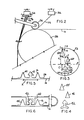
- the apparatus for forming a closure member and for joining the closure member to a traveling film web is generally shown in Figure 1 and identified by reference number 10.
- the apparatus 10 includes a roll 14 from which a web of film 16 is drawn.
- the film has a thickness of from 0.025 to 0.2 mm, and generally has a constant thickness throughout its width.
- the film 16 can comprise a single layer of a plastic material, or a laminate consisting of two or more layers of a plastic material.
- a wide variety of polymeric materials can be used in the film 16 such as, for example, polyolefins and blends of polyolefins with other ethylenically unsaturated carboxylic acids or esters.
- HDPE high density polyethylene
- LDPE low density polyethylene
- HDPE high density polyethylene
- LDPE low density polyethylene
- Various multilayered film structures may also be used such as a 2-layered structure of nylon and LDPE or a 3-layered structure such as LDPE/EVOH/LDPE.
- the film After emerging from the roll 14, the film is drawn through a pair of idler rollers 18 for properly positioning of the film.
- idler rollers 18 can be used in place of idler rollers 19.
- the film 16 is then drawn into a forming and joining station 22 which includes a first extrusion means 24 for extruding a base member 26.
- the first extrusion means 24 includes a hopper 28 for receiving a plastic material, a body 30 which contains a heating means (not shown) for heating the plastic material into a molten state, and a screw auger (not shown) for advancing the molten material to and through a die block 32.
- the die block 32 includes a die slot (not shown) which has a generally strap-like cross-sectional shape for extruding a generally strap-shaped base member 26.
- the base member 26 so extruded preferably has a thickness of from 0.05 to 0.76 mm and a width of about 9.5 mm.
- the relative thickness of the base member 26 permits the base member 26 to serve as a heat sink, and to retain a considerably amount of residual heat after its extrusion. This retained residual heat helps to promote the fusion of the base member 26 to the film 16, and also helps promote the fusion of the closure profile and rib members to the base member 26, and hence to the film web 16.
- a polytetrafluoroethylene (PTFE) coated layer on roller 36 is provided for applying the base member 26 to the film 16 by pressing the base member 26 into engagement with the film 16, as best shown in Figure 2.
- the PTFE layer facilitates the bonding of the base member 26 to the film by driving out air pockets which might form between the underside surface of the base member 26 and film 16. The removal of these air pockets helps to ensure the formation of a good bond between the base member 26 and film 16.
- a second extrusion means 40 is provided for extruding a male closure profile member 42, a first rib member 44 and a second rib member 46, which form the three primary components of the male portion of the zipper-like fastener of the invention.
- the second extrusion means 40 includes a hopper 48 and a body 50 which are similar in structure and function to the hopper 28 and body 30 of first extrusion means 24.
- the second extrusion means includes a die block 52 having a male profile member die slot 56, a first rib member die slot 58, and a second rib member die slot 60, through which the profile member 42, first rib member 44, and second rib member 46, respectively, are extruded as three separate extrudates.
- the male profile member die slot 56 typically has an arrow-shaped head portion 62, a shaft portion 64, and a generally arcuate tail portion 66, to yield a male profile member 42 having similarly shaped head, shaft and tail portions.
- Other male profiles shapes may also be utilized.
- the first and second rib member die slots 58, 60 may be of a similar shape.
- both die slots 58 and 60 comprise isosceles triangles in cross-section.
- each rib member die slot 58, 60 can have a pair of 70° base angles and a 40° apex angle.
- the rib member die slots 58, 60 are vertically offset from each other, and are each vertically offset from the profile member die slot 56. Additionally, the rib member die slots 58, 60 are offset laterally from each other.
- the following example is provided which is illustrative of the relative size and spacing of the three die slots 56, 58, 60. This example is not intended to be limiting. Other dimensions and spacings may be utilized depending upon the desired size and spacing of the elements for a given application. The dimensions set forth in the following example are given relative to an imaginary longitudinal bisector A which bisects the closure profile die slot 56, and an imaginary latitudinal bisector B.
- the distance C between the center of the profile die slot 56, and the latitudinal bisector B is 6.35 mm.
- the distance D between the base of the second rib member die slot 60 and the latitudinal bisector B is 0.9 mm.
- the distance E between the base of the first rib member die slot 58 and the latitudinal bisector B is 7.35 inches.
- the vertical spacing between the apex of the second rib member die slot 60 and the base of the first rib member die slot 58 is 1.6 mm.
- the distance H between the apex of the first rib member die slot 58 and the longitudinal bisector A, and the distance J between the apex of the second rib member die-slot 60 and the longitudinal bisector A are each 2.15 mm, thus yielding a horizontal spacing of 4.3 mm between the apices (and hence the vertical axes) of the first and second rib member die slots 58, 60.
- This horizontal spacing between the rib member die slots 58, 60 is chosen to yield the proper spacing between the rib members 44 and 46 when the rib members become joined to the film 16.
- the spacing between the apices of the first and second rib members 44, 46 should generally be between about 3.4 and 4.6 mm.
- the distance at which the rib members 44, 46 are spaced when they are applied to the film 16 will correspond generally to the horizontal (lateral) spacing between the rib member die slots 58, 60.
- the 4.3 mm spacing between the first and second rib member die slots 58, 60 will result in a lateral spacing K of approximately 4.3 mm between the applied rib members 44, 46.
- the preferred lateral spacing between the first and second rib members is between about 3.4 and 4.6 mm
- the preferred lateral spacing between the rib member die slots 58, 60 should be between about 3.4 and 4.6 mm.
- the size of the rib members may be reduced.
- the proper spacing is then maintained between the rib members because the smaller size of the rib members increases the space between each of the rib members and the profile member.
- the reduced size of the rib members also reduces the ability of the rib members to stiffen the area of the film adjacent to the profile member and thus, the effectiveness of the zipper is reduced, if not totally impaired.
- the vertically offset configuration of the die slots 56, 58, 60 shown in Figure 3 permits properly sized rib members to be extruded without becoming blended in with the profile member 42, and while still preserving the proper spatial alignment between the first and second rib members 44, 46 and the profile member 42 when the profile and rib members are applied to the film 16.
- the rib members 44, 46 should be spaced far enough apart to permit a pair of prongs provided on the female closure member 68 to be inserted interiorly of the rib members 44, 46 and exteriorly of the profile member 42, while being sufficiently close together to stiffen the area of the film 16 adjacent to the profile member 42.
- the die block 72 includes a profile die slot 74, a first rib member die slot 76, and a second rib member die slot 78, through which a male profile member 80, first rib member 82, and a second rib member 84, respectively, are extruded as separate extrudates.
- the position, size and shape of the profile die slot 74 is similar to profile die slot 56.
- first and second rib member die slots 76, 78 have a generally circular cross section, and are thus different from the rib member die slots 58, 60, the relative placement of the respective first rib member die slots 58, 76 and second rib member die slots 60, 78 is similar for both die blocks 52, 72.
- the zipper-like fastener formed from the profile and rib members 74,76, and 78 extruded from die block 72 is similar to the zipper formed from the extrudates of die block 52, except insofar as the cross-sectional shape of the rib members differ from each other.
- Rib members 82, 84, having a circular cross-section are preferred in some applications because triangular rib members 44, 46 can rotate during their travel from the die block 52 to the film 16, thus causing one or both of the rib members 44, 46 to engage the film 16 in a "tipped over" position. In a tipped over position, one of the side legs of the rib members 44, 46 engages the upper surface of the base member 26, rather than the base leg of the rib member 44, 46 engaging the upper surface.
- the base member 26 is joined to the film 16, and the profile 42 and rib members 44, 46 are subsequently joined to the upper surface of the base member 26. Due to the ability of the base member 26 to retain residual heat, and due to the short distance (and hence time) between the point at which the base member 26 is joined to the film 16, and the point at which the profile and rib members 42, 44, 46 are joined to the base member, it will be apparent that the closure profile 42 and rib members 44, 46 will become joined to the base member 26 before the base member 26 has cooled to an ambient temperature. The residual heat retained by the base member 26 fosters fusion between the closure profile 42 and rib members 44, 46 and the base member 25.
- the lamination roll 86 serves the dual purpose of providing a backing support to facilitate engagement of the base member 26, closure profile 42 and rib members 44, 46, and also serves to cool, and thereby solidify and bond the base member 26, profile 42 and rib members 44, 46 to each other and to the film 16.
- the closure member bonded to film 16 travels past a pair of water jets (not shown) and around idler rolls 90, 92.
- the water jets accelerate cooling of the base member 26, profile 42 and rib members 44, 46 to further solidify and bond them to each other and to the film 16, and to help cool the above components to an ambient temperature.
- the film 16 then passes around a pair of idler rollers 94, 96 and through a pair of drive rollers 98. After passing through drive rollers 98, the film 16 is wound onto take up roller 100.
Claims (14)
- Procédé pour fixer un profil (42, 80) avec des nervures adjacentes (44, 46; 82, 84) sur une bande de film en mouvement (16) pour former une fermeture du type à glissière, procédé comportant les étapes consistant à:
extruder un élément formant profil de fermeture (42, 80), un premier élément formant nervure (44, 80) et un second élément formant nervure (46, 82) sous forme de trois extrudats distincts, et
fixer ledit premier élément formant profil de fermeture (42, 80), ledit premier élément formant nervure (44, 80) et ledit second élément formant nervure (46, 82) sur ladite bande de film (16) en alignement de façon telle que ledit élément formant profil de fermeture (42, 80) soit disposé entre ledit premier (44, 80) et ledit second (46, 82) éléments formant nervure. - Procédé selon la revendication 1, incluant les étapes consistant à extruder un élément (26) formant base de forme générale plane et à fixer ledit élément de base (26) à ladite bande de film (16) avant de fixer ledit élément formant profil de fermeture (42, 80) et lesdits éléments formant nervure (44, 46; 82, 40) audit élément de base (26).
- Procédé selon la revendication 2, incluant les étapes consistant à presser ledit élément de base (26), pour qu'il se fixe sur ladite bande de film (16), avec un rouleau (36) et à fixer ledit élément formant profil de fermeture (42, 80), ledit premier élément formant nervure (44, 80) et ledit second élément formant nervure (46, 82) audit élément de base (26) après que ledit élément de base (26) a été fixé à ladite bande de film (16) et avant que ledit élément de base (26) ait refroidi à la température ambiante.
- Procédé de la revendication 1, 2 ou 3, dans lequel ledit élément formant profil de fermeture (42, 80), ledit premier élément formant nervure (44, 82) et ledit second élément formant nervure (46, 84) sont extrudés à travers une filière d'extrusion (52, 72) présentant une fente (56, 74) formant filière pour le profil de fermeture, fente à travers laquelle ledit élément formant profil de fermeture (42, 80) est extrudé, une fente (58, 76) formant filière pour un premier élément formant nervure, fente à travers laquelle ledit premier élément formant nervure (44, 82) est extrudé, et une fente (60, 78) formant filière pour le second élément formant nervure, fente à travers laquelle ledit second élément formant nervure (46, 84) est extrudé.
- Procédé selon l'une quelconque des revendications précédentes, incluant l'étape consistant à extruder ledit élément formant profil de fermeture (42, 80) présentant, en section transversale, une portion de tête en forme de flèche, une portion formant tige et une portion de base en arc, et à extruder ledit premier (44, 82), et ledit second (46, 84) éléments formant nervure présentant, en section transversale, une forme générale triangulaire ou circulaire, et procédé dans lequel ledit premier (44, 82) et ledit second (46, 84) éléments formant nervure sont alignés sur ladite bande de film (16) à une distance l'un de l'autre allant de 3,4 à 4,6 mm.
- Moyen d'extrusion (52, 72) pour extruder un élément formant profil de fermeture (42, 80), un premier élément formant nervure (44, 82) et un second élément formant nervure (46, 84) sur une bande de film (16) en matériau résineux synthétique, moyen comportant une filière d'extrusion (52, 72) présentant une fente (56, 74) formant filière d'un élément formant profil de fermeture, fente à travers laquelle ledit élément formant profil de fermeture (74, 80) est extrudé, une fente (58, 76) formant filière pour un premier élément formant nervure, fente à travers laquelle ledit premier élément formant nervure (44, 82) est extrudé, et une seconde fente (60, 78) formant filière pour un second élément formant nervure, fente à travers laquelle ledit second élément formant nervure (46, 84) est extrudé, la fente (56, 74) formant filière pour ledit élément formant profil de fermeture et les fentes (58, 76; 60, 78) formant filières pour lesdits premier et second éléments formant nervure étant disposées de façon à extruder ledit élément (42, 74) formant profil de fermeture et lesdits premier et second éléments formant nervure (44, 76; 46, 78) sous forme de trois extrudats distincts et pour amener ledit élément (42, 80) formant profil de fermeture et ledit premier (44, 76) et ledit second (46, 78) éléments formant nervure sur ladite bande de film (16) en alignement de façon que ledit élément (42, 80) formant profil de fermeture soit disposé entre ledit premier (44, 82) et ledit second (46, 84) éléments formant nervure.
- Moyen d'extrusion (52, 72) selon la revendication 6, dans lequel la fente (56, 74) formant filière pour ledit élément formant profil de fermeture et les fentes formant filière pour ledit premier (58, 76) et ledit second (60, 78) éléments formant nervure sont décalées verticalement l'une par rapport à l'autre.
- Moyen d'extrusion (52, 72) selon la revendication 7, dans lequel la fente (56, 74) formant filière pour ledit élément formant profil de fermeture présente un axe (A) substantiellement vertical bissecteur de ladite fente (56, 74) formant filière, la fente (58, 76) formant filière pour ledit premier élément formant nervure étant disposée d'un côté dudit axe (A) et la fente (60, 68) formant filière pour ledit second élément formant nervure étant disposée de l'autre côté dudit axe (A).
- Moyen d'extrusion (52, 72) de la revendication 7, dans lequel la fente (56, 74) formant filière pour ledit élément formant profil de fermeture présente une portion de tête (62) et dans lequel au moins l'une des fentes formant filière pour lesdits premier (58, 76) et second (60, 78) éléments formant nervure est décalée verticalement par rapport à ladite portion de tête (62) d'une distance supérieure à la distance (H) dont ladite fente (58, 76), formant filière pour ledit élément formant nervure est latéralement décalée par rapport à ladite portion de tête (62).
- Moyen d'extrusion (52, 72) selon les revendications 7, 8 ou 9, dans lequel les fentes formant filière pour lesdits premier (58,76) et second (60, 78) éléments formant nervure sont décalées latéralement l'une de l'autre d'une distance allant de 3,4 à 4,6 mm.
- Moyen d'extrusion (52, 72) selon l'une quelconque des revendications 6 à 10, dans lequel les fentes formant filière pour ledit premier (58, 76) et ledit second (60, 78) éléments formant nervure ont chacune une section transversale de forme générale triangulaire ou circulaire.
- Appareil (10) pour appliquer un profil de fermeture (42, 80) avec des nervures adjacentes (44, 46; 82, 84) sur une bande de film en mouvement (16) d'un matériau résine synthétique, appareil comportant:
un premier moyen d'extrusion (32) pour extruder un élément de base (26),
un moyen (36) pour presser ledit élément de base (26) contre ladite bande de film (16) et
un second moyen d'extrusion (52, 72b) pour extruder un élément formant profil de fermeture (42, 80), un premier élément formant nervure (44, 82) et un second élément formant nervure (46, 84) sous forme de trois extrudats distincts, ledit second moyen d'extrusion (52, 72) étant construit pour fixer ledit premier élément formant profil de fermeture (42, 80), ledit premier élément formant nervure (44, 82) et ledit second élément formant nervure (46, 84) à ladite bande de film (16), en alignement, de façon que ledit élément formant profil de fermeture (42, 80) soit disposé entre ledit premier (44, 80) et ledit second (46, 84) éléments formant nervure. - Appareil (10) selon la revendication 12, dans lequel ledit second moyen d'extrusion (52, 72) comporte une filière d'extrusion (52, 72) présentant une fente (56, 74) formant filière pour le profil de fermeture, fente à travers laquelle ledit élément formant profil de fermeture (42, 80) est extrudé, une fente (58, 72) formant filière pour le premier élément formant nervure, fente à travers laquelle ledit premier élément formant nervure (44, 76) est extrudé, et une fente (60, 70) formant filière pour le second élément formant nervure, fente à travers laquelle ledit second élément formant nervure (46, 84) est extrudé, et appareil dans lequel ladite fente (56, 74) formant filière pour le profil de fermeture est décalée verticalement par rapport à au moins l'une desdites fentes formant filière pour le premier (58, 76) et le second (60, 78) éléments formant nervure.
- Appareil (10) selon la revendication 13, dans lequel ladite fente (56, 74) formant filière du profil de fermeture est décalée verticalement par rapport à chacune, de ladite fente (58, 76) formant filière pour le premier élément formant nervure et de ladite fente (56, 78) formant filière pour le second élément formant nervure.
Applications Claiming Priority (2)
| Application Number | Priority Date | Filing Date | Title |
|---|---|---|---|
| US921023 | 1986-10-20 | ||
| US06/921,023 US4741789A (en) | 1986-10-20 | 1986-10-20 | Apparatus and process for forming and applying a profile and adjacent rib-type zipper to a traveling film web |
Publications (3)
| Publication Number | Publication Date |
|---|---|
| EP0265019A2 EP0265019A2 (fr) | 1988-04-27 |
| EP0265019A3 EP0265019A3 (en) | 1989-10-18 |
| EP0265019B1 true EP0265019B1 (fr) | 1993-01-20 |
Family
ID=25444795
Family Applications (1)
| Application Number | Title | Priority Date | Filing Date |
|---|---|---|---|
| EP87202004A Expired - Lifetime EP0265019B1 (fr) | 1986-10-20 | 1987-10-19 | Appareil et procédé pour former et appliquer les éléments d'une fermeture-éclair sur une bande en mouvement |
Country Status (12)
| Country | Link |
|---|---|
| US (1) | US4741789A (fr) |
| EP (1) | EP0265019B1 (fr) |
| JP (1) | JPH01133723A (fr) |
| KR (1) | KR880004920A (fr) |
| AR (1) | AR247353A1 (fr) |
| AU (1) | AU589812B2 (fr) |
| BR (1) | BR8705641A (fr) |
| CA (1) | CA1287718C (fr) |
| DE (1) | DE3783707T2 (fr) |
| HK (1) | HK94393A (fr) |
| MX (1) | MX161802A (fr) |
| NZ (1) | NZ222151A (fr) |
Families Citing this family (58)
| Publication number | Priority date | Publication date | Assignee | Title |
|---|---|---|---|---|
| US4822539A (en) * | 1987-09-14 | 1989-04-18 | Minigrip, Inc. | Method of and apparatus for extruding bag making material having fastener profiles and alignment ribs, with reinforcing and stabilizing beam effect ridge means |
| US5022530A (en) * | 1989-10-13 | 1991-06-11 | The Dow Chemical Company | Modified zipper elements for easy open containers |
| US5053091A (en) * | 1990-01-18 | 1991-10-01 | Packaging Innovations, Inc. | Method and apparatus for manufacturing plastic film with integral interlocking closure members incorporating shape conforming cooling shoes after extrusion |
| US5141577A (en) * | 1990-05-18 | 1992-08-25 | Dowbrands L.P. | Closure for reclosable thermoplastic containers |
| US5012561A (en) * | 1990-05-18 | 1991-05-07 | The Dow Chemical Company | Closure for reclosable thermoplastic containers |
| US5058761A (en) * | 1990-09-10 | 1991-10-22 | Bryan Foods, Inc. | Reclosable package and a base portion of the package |
| US5192135A (en) * | 1991-05-31 | 1993-03-09 | Dowbrands L.P. | Profile and adjacent rib-type closure element for reclosable thermoplastic bags |
| CA2198484C (fr) * | 1994-08-26 | 2007-01-09 | Zain E. M. Saad | Sacs pour conservation d'aliments au congelateur |
| US5558439A (en) * | 1995-06-08 | 1996-09-24 | Minigrip Inc. | Wedge zipper |
| US6550966B1 (en) | 1995-08-28 | 2003-04-22 | S.C. Johnson Home Storage, Inc. | Freezer storage bag |
| US6217216B1 (en) | 1996-02-22 | 2001-04-17 | Nossi Taheri | Reclosable plastic bag with non-perforated tear zone |
| US6371644B1 (en) * | 1997-05-22 | 2002-04-16 | Sealstrip Corp. | Reclosable seal, package, method and apparatus |
| US6350057B1 (en) * | 1997-05-22 | 2002-02-26 | Sealstrip Corp. | Reinforced reclosable package seals |
| US6080252A (en) * | 1997-10-06 | 2000-06-27 | Illinois Tool Works Inc. | Zipper component and method for forming same |
| US6149302A (en) * | 1999-05-05 | 2000-11-21 | Taheri; Nossi | Plastic bag with tamper-evident closure |
| US6371643B2 (en) | 1999-06-02 | 2002-04-16 | S. C. Johnson Home Storage, Inc. | Multi-Layered freezer storage bag |
| US6439771B1 (en) | 2000-03-15 | 2002-08-27 | Webster Industries Division Chelsea Industries, Inc. | Zippered resealable closure |
| US6562165B1 (en) * | 2000-08-15 | 2003-05-13 | S.C. Johnson Home Storage, Inc. | Method for laminating closure member to film web |
| US6519917B2 (en) * | 2000-10-23 | 2003-02-18 | Sealstrip Corporation | Method and apparatus for making gussetted package |
| DE60208760T2 (de) * | 2001-07-17 | 2006-07-20 | Japan Patent Management Co. Ltd. | Verfahren zur Herstellung eines ineinandergreifenden Profilleistenverschlusses für einen Beutel |
| US20030106635A1 (en) * | 2001-12-10 | 2003-06-12 | Mladomir Tomic | Method for manufacturing a resealable bag |
| US20030230377A1 (en) * | 2002-06-14 | 2003-12-18 | Turvey Robert R. | Apparatus and method for automated splicing of closer tape |
| US20030236158A1 (en) * | 2002-06-24 | 2003-12-25 | Pawloski James C. | Method of and apparatus for producing a reclosable pouch |
| US20040001651A1 (en) * | 2002-06-27 | 2004-01-01 | Pawloski James C. | Closure device for a reclosable pouch |
| US6994535B2 (en) * | 2002-06-27 | 2006-02-07 | S.C. Johnson Home Storage, Inc. | Method and apparatus for forming a guide rib on a section of plastic film |
| US6869495B2 (en) * | 2002-09-27 | 2005-03-22 | Charles A. Snooks | Article attachment device and method |
| US20040078938A1 (en) * | 2002-10-23 | 2004-04-29 | Pawloski James C. | Closure device for a reclosable pouch |
| US20050065007A1 (en) * | 2003-03-05 | 2005-03-24 | Tilia International, Inc. | Method for manufacturing a sealable bag having an integrated valve structure for use in vacuum packaging |
| US7087130B2 (en) * | 2003-03-05 | 2006-08-08 | Tilia International, Inc. | Method for manufacturing a sealable bag having an integrated zipper for use in vacuum packaging |
| US20040234171A1 (en) * | 2003-05-19 | 2004-11-25 | Dais Brian C. | Reclosable pouch with closure device that allows venting and/or an air-tight seal |
| US7137736B2 (en) | 2003-05-19 | 2006-11-21 | S.C. Johnson Home Storage, Inc. | Closure device for a reclosable pouch |
| US20040256761A1 (en) * | 2003-06-17 | 2004-12-23 | Pawloski James C. | Method of and apparatus for producing a reclosable pouch |
| US7223017B2 (en) * | 2003-12-19 | 2007-05-29 | Sonoco Development, Inc. | Side gusset bag with reclose feature |
| US7850368B2 (en) * | 2004-06-04 | 2010-12-14 | S.C. Johnson & Son, Inc. | Closure device for a reclosable pouch |
| US20050271308A1 (en) * | 2004-06-04 | 2005-12-08 | Pawloski James C | Closure device for a reclosable pouch |
| US7494333B2 (en) * | 2004-06-04 | 2009-02-24 | S.C. Johnson Home Storage, Inc. | Apparatus for forming multiple closure elements |
| US7419300B2 (en) | 2004-06-16 | 2008-09-02 | S.C. Johnson Home Storage, Inc. | Pouch having fold-up handles |
| DE202004018940U1 (de) * | 2004-12-07 | 2006-04-13 | Asf Verwaltungs Gmbh | Druckverschluß, Druckverschlußband und wiederverschließbarer Beutel |
| US7437805B2 (en) * | 2006-06-23 | 2008-10-21 | Edward Alan Berich | Reclosable storage bag closure with internal valving |
| US7784160B2 (en) | 2007-03-16 | 2010-08-31 | S.C. Johnson & Son, Inc. | Pouch and airtight resealable closure mechanism therefor |
| US8070359B2 (en) | 2007-05-15 | 2011-12-06 | Thunderbird Global Enterprises, Llc | Plastic bag with pour spout and reinforced bottom end |
| US8197139B2 (en) | 2007-06-15 | 2012-06-12 | S.C. Johnson Home Storage, Inc. | Valve and valve strip for a reclosable container |
| US8196269B2 (en) * | 2007-06-15 | 2012-06-12 | S.C. Johnson & Son, Inc. | Closure mechanism for a recloseable pouch |
| US8096329B2 (en) | 2007-06-15 | 2012-01-17 | S. C. Johnson & Son, Inc. | Hand-held vacuum pump |
| US8192182B2 (en) * | 2008-01-09 | 2012-06-05 | S.C. Johnson Home Storage, Inc. | Manual evacuation system |
| US8529129B2 (en) * | 2008-03-13 | 2013-09-10 | S.C. Johnson & Son, Inc. | Closure element for a pouch |
| US8197138B2 (en) * | 2008-08-12 | 2012-06-12 | S.C. Johnson & Son, Inc. | Evacuable container and evacuation strip therefor |
| US8578572B2 (en) | 2009-05-29 | 2013-11-12 | S.C. Johnson & Son, Inc. | Closure mechanism and method of closing |
| US8591109B2 (en) | 2009-09-24 | 2013-11-26 | S.C. Johnson & Son, Inc. | Stand-up pouch with a collapsible body |
| DE102009046717A1 (de) * | 2009-11-16 | 2011-05-19 | Robert Bosch Gmbh | Verfahren und Vorrichtung zur Herstellung eines Verpackungsbeutels aus flexiblem Folienmaterial sowie Verpackungsbeutel |
| DE102010019837A1 (de) | 2010-05-08 | 2011-11-10 | Dietmar G. Turnau | Abhörschutztasche für Drahtlos-Kommunikationsgerät als Mittel gegen Fremdmanipulation und Bespitzelung zur zeitweiligen Nutzung während vertraulicher Besprechungen |
| US8550716B2 (en) | 2010-06-22 | 2013-10-08 | S.C. Johnson & Son, Inc. | Tactile enhancement mechanism for a closure mechanism |
| US11180286B2 (en) | 2010-10-29 | 2021-11-23 | S. C. Johnson & Son, Inc. | Reclosable bag having a loud sound during closing |
| US9327875B2 (en) | 2010-10-29 | 2016-05-03 | S.C. Johnson & Son, Inc. | Reclosable bag having a loud sound during closing |
| US8974118B2 (en) | 2010-10-29 | 2015-03-10 | S.C. Johnson & Son, Inc. | Reclosable bag having a sound producing zipper |
| JP2012131563A (ja) * | 2010-12-24 | 2012-07-12 | C I Kasei Co Ltd | 嵌合具および嵌合具付き袋体 |
| US8469593B2 (en) | 2011-02-22 | 2013-06-25 | S.C. Johnson & Son, Inc. | Reclosable bag having a press-to-vent zipper |
| US8568031B2 (en) | 2011-02-22 | 2013-10-29 | S.C. Johnson & Son, Inc. | Clicking closure device for a reclosable pouch |
Family Cites Families (26)
| Publication number | Priority date | Publication date | Assignee | Title |
|---|---|---|---|---|
| US3008862A (en) * | 1956-06-29 | 1961-11-14 | Union Carbide Corp | Extruded bead sealing |
| US3034941A (en) * | 1957-11-01 | 1962-05-15 | Union Carbide Corp | Tear beaded wrapping material |
| GB994307A (en) * | 1961-11-27 | 1965-06-02 | Seisan Nipponsha Kk | Material for forming plastics bags and bags made therefrom |
| US3380481A (en) * | 1962-03-02 | 1968-04-30 | Minigrip Inc | Closed tube with fastener members |
| US3226787A (en) * | 1962-05-17 | 1966-01-04 | Ausnit Steven | Double extruded fastener strips |
| US3338284A (en) * | 1963-07-22 | 1967-08-29 | Ausnit Steven | Sheet with fastener structure |
| US3462332A (en) * | 1965-03-05 | 1969-08-19 | High Polymer Chem Ind Ltd | Method of continuously providing a fastener on a thermoplastic film |
| US3540975A (en) * | 1967-08-17 | 1970-11-17 | Wright Co Wm E | Iron-on trims and findings |
| US3685562A (en) * | 1971-03-03 | 1972-08-22 | Steven Ausnit | Flexible pilfer proof closure construction for bags |
| US3765809A (en) * | 1972-03-10 | 1973-10-16 | J Farrell | Apparatus for making plastic articles of irregular design |
| DE2223780B2 (de) * | 1972-05-16 | 1976-03-18 | Reifenhäuser KG, 5210 Troisdorf | Verfahren und vorrichtung zur herstellung von bikomponentenfasern |
| US4259133A (en) * | 1973-03-13 | 1981-03-31 | Minigrip, Inc. | Method and apparatus for making profile sheets |
| US4101355A (en) * | 1977-01-21 | 1978-07-18 | Steven Ausnit | Method of and means for making variable width zipper profile film |
| US4263079A (en) * | 1978-12-15 | 1981-04-21 | The Dow Chemical Company | Method of forming an integral closure for a thermoplastic container |
| DE3011371C2 (de) * | 1979-03-30 | 1985-03-14 | Union Carbide Corp., New York, N.Y. | Extrudiervorrichtung zur Herstellung von Verschlußstreifen aus Kunststoff |
| US4540537A (en) * | 1979-03-30 | 1985-09-10 | Union Carbide Corporation | Method and extruding die apparatus for producing a plastic closure strip |
| US4290989A (en) * | 1979-12-10 | 1981-09-22 | Frito-Lay, Inc. | Method and apparatus for extruding a plurality of ribbons |
| US4363345A (en) * | 1980-06-02 | 1982-12-14 | Union Carbide Corporation | Reclosable container |
| GB2116115B (en) * | 1982-03-03 | 1986-04-09 | Copely Dev Ltd | Plastics strips |
| US4392897A (en) * | 1982-04-05 | 1983-07-12 | Mobil Oil Corporation | Manufacturing process for channel seal |
| US4419159A (en) * | 1982-04-05 | 1983-12-06 | Mobil Oil Corporation | Manufacture of plastic bags with interlocking profile extrusions |
| US4428788A (en) * | 1982-05-14 | 1984-01-31 | Union Carbide Corporation | Film-tape-closure device slot cast integrated interlocking structure and extrusion method |
| US4484352A (en) * | 1983-02-07 | 1984-11-20 | Katzin Lawrence F | Reclosable plastic bag |
| JPS60125651A (ja) * | 1983-12-02 | 1985-07-04 | Seisan Nipponsha Kk | プラスチツクフアスナ−並びにプラスチツク付加物をフイルムに成形接着する方法 |
| US4562027A (en) * | 1984-03-21 | 1985-12-31 | The Dow Chemical Company | Process for making cast thermoplastic film with integral closures |
| US4683015A (en) * | 1985-07-09 | 1987-07-28 | The Dow Chemical Company | Method of forming flexible fastener elements and securing them to a traveling web |
-
1986
- 1986-10-20 US US06/921,023 patent/US4741789A/en not_active Expired - Lifetime
-
1987
- 1987-09-09 CA CA000546397A patent/CA1287718C/fr not_active Expired - Lifetime
- 1987-10-07 JP JP62253481A patent/JPH01133723A/ja active Granted
- 1987-10-13 NZ NZ222151A patent/NZ222151A/en unknown
- 1987-10-16 BR BR8705641A patent/BR8705641A/pt unknown
- 1987-10-19 AU AU79891/87A patent/AU589812B2/en not_active Ceased
- 1987-10-19 MX MX8896A patent/MX161802A/es unknown
- 1987-10-19 DE DE8787202004T patent/DE3783707T2/de not_active Expired - Fee Related
- 1987-10-19 EP EP87202004A patent/EP0265019B1/fr not_active Expired - Lifetime
- 1987-10-20 KR KR870011633A patent/KR880004920A/ko not_active Application Discontinuation
- 1987-10-20 AR AR87309021A patent/AR247353A1/es active
-
1993
- 1993-09-09 HK HK943/93A patent/HK94393A/xx unknown
Also Published As
| Publication number | Publication date |
|---|---|
| EP0265019A3 (en) | 1989-10-18 |
| AR247353A1 (es) | 1994-12-29 |
| HK94393A (en) | 1993-09-17 |
| DE3783707D1 (de) | 1993-03-04 |
| MX161802A (es) | 1990-12-28 |
| BR8705641A (pt) | 1988-05-31 |
| AU7989187A (en) | 1988-04-21 |
| US4741789A (en) | 1988-05-03 |
| CA1287718C (fr) | 1991-08-20 |
| JPH0515374B2 (fr) | 1993-03-01 |
| DE3783707T2 (de) | 1993-05-13 |
| KR880004920A (ko) | 1988-06-27 |
| NZ222151A (en) | 1990-04-26 |
| JPH01133723A (ja) | 1989-05-25 |
| EP0265019A2 (fr) | 1988-04-27 |
| AU589812B2 (en) | 1989-10-19 |
Similar Documents
| Publication | Publication Date | Title |
|---|---|---|
| EP0265019B1 (fr) | Appareil et procédé pour former et appliquer les éléments d'une fermeture-éclair sur une bande en mouvement | |
| EP0273327B1 (fr) | Procédé et dispositif de fabrication de film pour sachet refermable | |
| EP0339324B1 (fr) | Bande de fermeture à profilés d'accouplement, sachets munis de celle-ci, procédé et appareil de fabrication pour ces sachets et procédé et appareil de remplissage pour ces sachets | |
| US3532571A (en) | Method and apparatus for forming continuous plastic tubing with separable pressure reclosable fastener strips attached to the surface thereof | |
| US6860952B2 (en) | Method for laminating closure member to film web | |
| US4787755A (en) | Reclosable flexible container having fastener profiles sealed at their ends to the outside of the bag | |
| US6138329A (en) | Fastener assembly, fastener tape material, bag utilizing fastener tape material, and method of manufacture thereof | |
| US3853671A (en) | Apparatus for making multiple plastic bags with reclosable fastener thereon | |
| US4528224A (en) | Method of making multiple reclosable bag material | |
| CN1183008C (zh) | 多层的冷冻贮存袋 | |
| EP0208277B1 (fr) | Eléments d'accrochage flexibles et procédé pour leur fixation à une feuille en mouvement | |
| US20030021500A1 (en) | Method for making a multicompartment thermoplastic bag | |
| CA1242860A (fr) | Faconnage de feuille plastique a elements de fermeture incorpores | |
| US20040078939A1 (en) | Closure device for a reclosable pouch | |
| US4629524A (en) | Making reclosable bag material | |
| US20040001651A1 (en) | Closure device for a reclosable pouch | |
| US6994535B2 (en) | Method and apparatus for forming a guide rib on a section of plastic film | |
| CA1243166A (fr) | Methode de fabrication d'une fermeture autoagrippante en plastique | |
| JP2560394B2 (ja) | モールディングの製造方法 | |
| JPS6038142A (ja) | 複層袋の製造方法 | |
| EP1467920A1 (fr) | Dispositif de fermeture pour sachet refermable | |
| JPH1149192A (ja) | テープ式ジッパー及びジッパー袋 | |
| KR20050023342A (ko) | 다중 격실 열가소재 백의 제조 방법 | |
| NZ211483A (en) | Extruding plastics fastener and accessory strip and uniting with film |
Legal Events
| Date | Code | Title | Description |
|---|---|---|---|
| PUAI | Public reference made under article 153(3) epc to a published international application that has entered the european phase |
Free format text: ORIGINAL CODE: 0009012 |
|
| AK | Designated contracting states |
Kind code of ref document: A2 Designated state(s): BE DE FR GB IT NL SE |
|
| PUAL | Search report despatched |
Free format text: ORIGINAL CODE: 0009013 |
|
| AK | Designated contracting states |
Kind code of ref document: A3 Designated state(s): BE DE FR GB IT NL SE |
|
| 17P | Request for examination filed |
Effective date: 19900418 |
|
| 17Q | First examination report despatched |
Effective date: 19910524 |
|
| RAP1 | Party data changed (applicant data changed or rights of an application transferred) |
Owner name: DOWBRANDS INC. |
|
| GRAA | (expected) grant |
Free format text: ORIGINAL CODE: 0009210 |
|
| AK | Designated contracting states |
Kind code of ref document: B1 Designated state(s): BE DE FR GB IT NL SE |
|
| ET | Fr: translation filed | ||
| REF | Corresponds to: |
Ref document number: 3783707 Country of ref document: DE Date of ref document: 19930304 |
|
| ITF | It: translation for a ep patent filed |
Owner name: ING. A. GIAMBROCONO & C. S.R.L. |
|
| PLBE | No opposition filed within time limit |
Free format text: ORIGINAL CODE: 0009261 |
|
| STAA | Information on the status of an ep patent application or granted ep patent |
Free format text: STATUS: NO OPPOSITION FILED WITHIN TIME LIMIT |
|
| 26N | No opposition filed | ||
| PGFP | Annual fee paid to national office [announced via postgrant information from national office to epo] |
Ref country code: FR Payment date: 19940812 Year of fee payment: 8 |
|
| PGFP | Annual fee paid to national office [announced via postgrant information from national office to epo] |
Ref country code: SE Payment date: 19940819 Year of fee payment: 8 |
|
| PGFP | Annual fee paid to national office [announced via postgrant information from national office to epo] |
Ref country code: DE Payment date: 19940822 Year of fee payment: 8 |
|
| PGFP | Annual fee paid to national office [announced via postgrant information from national office to epo] |
Ref country code: BE Payment date: 19940909 Year of fee payment: 8 |
|
| PGFP | Annual fee paid to national office [announced via postgrant information from national office to epo] |
Ref country code: GB Payment date: 19940930 Year of fee payment: 8 |
|
| PGFP | Annual fee paid to national office [announced via postgrant information from national office to epo] |
Ref country code: NL Payment date: 19941031 Year of fee payment: 8 |
|
| EAL | Se: european patent in force in sweden |
Ref document number: 87202004.5 |
|
| PG25 | Lapsed in a contracting state [announced via postgrant information from national office to epo] |
Ref country code: GB Effective date: 19951019 |
|
| PG25 | Lapsed in a contracting state [announced via postgrant information from national office to epo] |
Ref country code: SE Effective date: 19951020 |
|
| PG25 | Lapsed in a contracting state [announced via postgrant information from national office to epo] |
Ref country code: BE Effective date: 19951031 |
|
| BERE | Be: lapsed |
Owner name: DOWBRANDS INC. Effective date: 19951031 |
|
| PG25 | Lapsed in a contracting state [announced via postgrant information from national office to epo] |
Ref country code: NL Effective date: 19960501 |
|
| GBPC | Gb: european patent ceased through non-payment of renewal fee |
Effective date: 19951019 |
|
| PG25 | Lapsed in a contracting state [announced via postgrant information from national office to epo] |
Ref country code: FR Effective date: 19960628 |
|
| EUG | Se: european patent has lapsed |
Ref document number: 87202004.5 |
|
| PG25 | Lapsed in a contracting state [announced via postgrant information from national office to epo] |
Ref country code: DE Effective date: 19960702 |
|
| NLV4 | Nl: lapsed or anulled due to non-payment of the annual fee |
Effective date: 19960501 |
|
| REG | Reference to a national code |
Ref country code: FR Ref legal event code: ST |
|
| PG25 | Lapsed in a contracting state [announced via postgrant information from national office to epo] |
Ref country code: IT Free format text: LAPSE BECAUSE OF NON-PAYMENT OF DUE FEES Effective date: 20051019 |