EP0264927B1 - Bildwiedergabeanordnung mit einer Bildröhre und Verfahren zur Herstellung - Google Patents
Bildwiedergabeanordnung mit einer Bildröhre und Verfahren zur Herstellung Download PDFInfo
- Publication number
- EP0264927B1 EP0264927B1 EP87115406A EP87115406A EP0264927B1 EP 0264927 B1 EP0264927 B1 EP 0264927B1 EP 87115406 A EP87115406 A EP 87115406A EP 87115406 A EP87115406 A EP 87115406A EP 0264927 B1 EP0264927 B1 EP 0264927B1
- Authority
- EP
- European Patent Office
- Prior art keywords
- liquid crystal
- film
- polymer
- picture tube
- front panel
- Prior art date
- Legal status (The legal status is an assumption and is not a legal conclusion. Google has not performed a legal analysis and makes no representation as to the accuracy of the status listed.)
- Expired - Lifetime
Links
- 238000004519 manufacturing process Methods 0.000 title claims description 4
- 239000004973 liquid crystal related substance Substances 0.000 claims description 36
- 210000002858 crystal cell Anatomy 0.000 claims description 21
- 239000000853 adhesive Substances 0.000 claims description 12
- 230000001070 adhesive effect Effects 0.000 claims description 12
- 239000010410 layer Substances 0.000 claims description 11
- 229920000642 polymer Polymers 0.000 claims description 11
- 239000005262 ferroelectric liquid crystals (FLCs) Substances 0.000 claims description 10
- 238000000034 method Methods 0.000 claims description 5
- 239000000463 material Substances 0.000 claims description 4
- 239000012790 adhesive layer Substances 0.000 claims description 3
- 238000003475 lamination Methods 0.000 claims description 2
- 239000002861 polymer material Substances 0.000 claims description 2
- 230000010287 polarization Effects 0.000 claims 6
- 239000012799 electrically-conductive coating Substances 0.000 claims 3
- 238000010030 laminating Methods 0.000 claims 1
- 239000005264 High molar mass liquid crystal Substances 0.000 description 11
- 150000001875 compounds Chemical class 0.000 description 5
- 239000000178 monomer Substances 0.000 description 3
- SMZOUWXMTYCWNB-UHFFFAOYSA-N 2-(2-methoxy-5-methylphenyl)ethanamine Chemical compound COC1=CC=C(C)C=C1CCN SMZOUWXMTYCWNB-UHFFFAOYSA-N 0.000 description 2
- NIXOWILDQLNWCW-UHFFFAOYSA-N 2-Propenoic acid Natural products OC(=O)C=C NIXOWILDQLNWCW-UHFFFAOYSA-N 0.000 description 2
- 239000004020 conductor Substances 0.000 description 2
- 239000011521 glass Substances 0.000 description 2
- 125000005397 methacrylic acid ester group Chemical group 0.000 description 2
- 229920000106 Liquid crystal polymer Polymers 0.000 description 1
- 238000004026 adhesive bonding Methods 0.000 description 1
- 125000004432 carbon atom Chemical group C* 0.000 description 1
- 239000011248 coating agent Substances 0.000 description 1
- 238000000576 coating method Methods 0.000 description 1
- 230000008878 coupling Effects 0.000 description 1
- 238000010168 coupling process Methods 0.000 description 1
- 238000005859 coupling reaction Methods 0.000 description 1
- 230000000694 effects Effects 0.000 description 1
- 125000000896 monocarboxylic acid group Chemical group 0.000 description 1
- 230000003287 optical effect Effects 0.000 description 1
- 230000000379 polymerizing effect Effects 0.000 description 1
- 229920001296 polysiloxane Polymers 0.000 description 1
- 239000007787 solid Substances 0.000 description 1
Images
Classifications
-
- G—PHYSICS
- G02—OPTICS
- G02F—OPTICAL DEVICES OR ARRANGEMENTS FOR THE CONTROL OF LIGHT BY MODIFICATION OF THE OPTICAL PROPERTIES OF THE MEDIA OF THE ELEMENTS INVOLVED THEREIN; NON-LINEAR OPTICS; FREQUENCY-CHANGING OF LIGHT; OPTICAL LOGIC ELEMENTS; OPTICAL ANALOGUE/DIGITAL CONVERTERS
- G02F1/00—Devices or arrangements for the control of the intensity, colour, phase, polarisation or direction of light arriving from an independent light source, e.g. switching, gating or modulating; Non-linear optics
- G02F1/01—Devices or arrangements for the control of the intensity, colour, phase, polarisation or direction of light arriving from an independent light source, e.g. switching, gating or modulating; Non-linear optics for the control of the intensity, phase, polarisation or colour
- G02F1/13—Devices or arrangements for the control of the intensity, colour, phase, polarisation or direction of light arriving from an independent light source, e.g. switching, gating or modulating; Non-linear optics for the control of the intensity, phase, polarisation or colour based on liquid crystals, e.g. single liquid crystal display cells
- G02F1/133—Constructional arrangements; Operation of liquid crystal cells; Circuit arrangements
- G02F1/1333—Constructional arrangements; Manufacturing methods
- G02F1/133365—Cells in which the active layer comprises a liquid crystalline polymer
-
- G—PHYSICS
- G02—OPTICS
- G02F—OPTICAL DEVICES OR ARRANGEMENTS FOR THE CONTROL OF LIGHT BY MODIFICATION OF THE OPTICAL PROPERTIES OF THE MEDIA OF THE ELEMENTS INVOLVED THEREIN; NON-LINEAR OPTICS; FREQUENCY-CHANGING OF LIGHT; OPTICAL LOGIC ELEMENTS; OPTICAL ANALOGUE/DIGITAL CONVERTERS
- G02F1/00—Devices or arrangements for the control of the intensity, colour, phase, polarisation or direction of light arriving from an independent light source, e.g. switching, gating or modulating; Non-linear optics
- G02F1/01—Devices or arrangements for the control of the intensity, colour, phase, polarisation or direction of light arriving from an independent light source, e.g. switching, gating or modulating; Non-linear optics for the control of the intensity, phase, polarisation or colour
- G02F1/13—Devices or arrangements for the control of the intensity, colour, phase, polarisation or direction of light arriving from an independent light source, e.g. switching, gating or modulating; Non-linear optics for the control of the intensity, phase, polarisation or colour based on liquid crystals, e.g. single liquid crystal display cells
- G02F1/1313—Devices or arrangements for the control of the intensity, colour, phase, polarisation or direction of light arriving from an independent light source, e.g. switching, gating or modulating; Non-linear optics for the control of the intensity, phase, polarisation or colour based on liquid crystals, e.g. single liquid crystal display cells specially adapted for a particular application
-
- H—ELECTRICITY
- H01—ELECTRIC ELEMENTS
- H01J—ELECTRIC DISCHARGE TUBES OR DISCHARGE LAMPS
- H01J29/00—Details of cathode-ray tubes or of electron-beam tubes of the types covered by group H01J31/00
- H01J29/86—Vessels; Containers; Vacuum locks
- H01J29/89—Optical or photographic arrangements structurally combined or co-operating with the vessel
-
- H—ELECTRICITY
- H01—ELECTRIC ELEMENTS
- H01J—ELECTRIC DISCHARGE TUBES OR DISCHARGE LAMPS
- H01J2229/00—Details of cathode ray tubes or electron beam tubes
- H01J2229/89—Optical components associated with the vessel
- H01J2229/8913—Anti-reflection, anti-glare, viewing angle and contrast improving treatments or devices
- H01J2229/8922—Apparatus attached to vessel and not integral therewith
Definitions
- the invention relates to a picture tube arrangement for displaying polarized images and to a method for producing such an arrangement.
- a picture tube arrangement with a picture tube with a front pane, a polarizer and a liquid crystal cell is disclosed in EP-A-0 136 696. However, it does not describe exactly how the arrangement is made; however, it is believed that the polarizer and the liquid crystal cell are attached to the frame of the picture tube or that the picture tube, the polarizer and the liquid crystal cell are held by a common housing.
- the picture tube arrangement according to the invention is characterized in that a polarizer and a film-shaped liquid crystal cell are arranged directly on the windshield of the picture tube, preferably by gluing to the windshield.
- the direct connection of the polarizing film and the liquid crystal film to the front pane results in a compactness of the overall arrangement which can no longer be beaten. Paralax effects are completely excluded, so that the usable viewing angle only depends on the properties of the liquid crystal cell.
- the method according to the invention is characterized in that a polarizing film and a liquid crystal film are connected to one another by lamination and in that the laminate is glued to the front pane of a picture tube.
- the liquid crystal film advantageously consists of a polymer, preferably a polymer with ferroelectric liquid crystal material.
- a ferroelectric liquid crystal polymer material is known per se from EP-A-0 228 703. Ferroelectric liquid crystals switch particularly quickly.
- ferroelectric liquid crystal compounds examples are given below.
- Graftable ferroelectric liquid crystal compounds where X is a group suitable for coupling to polymer chains for example organopolysiloxanes, for example OH, NH2, COOH.
- the C atoms are denoted by an x, which determine the chiral properties of the liquid crystals.
- Polymer liquid crystal films in which the switching speed has been significantly increased by ferroelectric liquid crystal compounds, also offer significant advantages for other applications, for example for liquid crystal displays which are suitable for displaying moving images.
- the idea of constructing a liquid crystal film with ferroelectric liquid crystal material therefore has an independent inventive meaning which goes far beyond the application in the subject matter of the present claim 1.
- Such polymer liquid crystal films with ferroelectric liquid crystal material can be obtained not only by grafting suitable liquid crystal compounds onto suitable polymer chains, but also by polymerizing suitable monomers.
- suitable monomers based on acrylic acid and methacrylic acid esters are given below.
- the transparent electrodes for switching the liquid crystal cell are arranged on the inner side of the glass plates.
- the transparent electrode layers are arranged on the outside of the film, so that they can be easily contacted. It is particularly simple in the present arrangement to use at least partially an adhesive layer made of a conductive adhesive, which at the same time serves for contacting the transparent electrode layers.
- the conductive adhesive which is usually not transparent, can be arranged in hidden areas outside the image area of the screen.
- a particularly simple method of manufacturing an arrangement according to the invention is that the polarizing film and the polymer liquid crystal film are first laminated, i.e. be joined together by the action of pressure and / or heat, so that the laminate can be glued as a single part onto the windshield of the picture tube.
- the polymer liquid crystal film can first be provided on both sides with a transparent, electrically conductive layer, after which the polarizing film is laminated onto one side of the polymer liquid crystal film and the laminate is then glued onto the front pane of the picture tube with a transparent adhesive.
- Another possibility is to provide the polarizing film on one side with a transparent, electrically conductive layer and likewise to provide the polymer liquid crystal film with a transparent electrically conductive layer on one side.
- the two films are then laminated to one another in such a way that the coated side of the polarizing film comes to lie on the uncoated side of the polymer liquid crystal film.
- conductive layers are also arranged on both sides of the polymer liquid crystal film, without the need for a double-sided coating, as in the previously described methods.
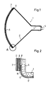
- the picture tube 1 consists of a piston 2 which merges into the neck 3 on one side, on which the base 4 is arranged. and which, on the other hand, merges into the front screen 5, to which a polymer liquid crystal film 6 and a polarizing film 7 arranged thereon are connected according to the invention.
- the two films 6 and 7 can be connected to one another and to the front pane 5 of the picture tube 1 by a transparent adhesive, but it can also, as described above, first form a laminate from the films 6 and 7, which as a unit on the front pane 5 of the picture tube 1 is glued on with a transparent adhesive.
- Fig. 2 From Fig. 2 it can be seen that transparent conductor layers 10 and 11 are arranged on both sides of the polymer liquid crystal film 6, and that the polarizing film 7 is arranged on the conductor layer 11.
- the arrangement of layers 6, 7, 10 and 11, which preferably form a laminate, is glued to the front pane 5 of the picture tube by means of the transparent adhesive layer 8. Outside the image area, part of the adhesive consists of a conductive adhesive 9 which is connected to the corresponding control circuit via a feed line 12.
Landscapes
- Physics & Mathematics (AREA)
- Nonlinear Science (AREA)
- Chemical & Material Sciences (AREA)
- Crystallography & Structural Chemistry (AREA)
- General Physics & Mathematics (AREA)
- Optics & Photonics (AREA)
- Mathematical Physics (AREA)
- Liquid Crystal (AREA)
- Vessels, Lead-In Wires, Accessory Apparatuses For Cathode-Ray Tubes (AREA)
- Devices For Indicating Variable Information By Combining Individual Elements (AREA)
Description
- Die Erfindung betrifft eine Bildröhrenanordnung zum Wiedergeben polarisierter Bilder sowie ein Verfahren zum Herstellen einer solchen Anordnung.
- Eine Bildröhrenanordnung mit einer Bildröhre mit einer Frontscheibe, einem Polarisator und einer Flüssigkristallzelle ist in EP-A-0 136 696 offenbart. Es wird dort allerdings nicht genau beschrieben, wie die Anordnung hergestellt wird; es ist jedoch anzunehmen, daß der Polarisator und die Flüssigkristallzelle am Rahmen der Bildröhre befestigt werden oder daß die Bildröhre, der Polarisator und die Flüssigkristallzelle durch ein gemeinsames Gehäuse gehalten werden.
- Aus US-A-4,048,358 ist eine Bildröhrenanordnung mit einer Bildröhre und einer folienförmigen Flüssigkristallzelle bekannt. Die Flüssigkristallzelle ist beidseitig mit durchsichtigen Elektrodenflächen versehen. Auch diese Veröffentlichung beschreibt nicht, wie die Flüssigkristallzelle und die Bildröhre in fester gegenseitiger Beziehung gehalten werden, jedoch zeigt eine persektivische Darstellung deutlich, daß die folienförmige Flüssigkristallzelle in der Ebene eines Gehäuses mit eben ausgebildeter Frontfläche liegt. Die folienförmige Flüssigkristallzelle scheint also unmittelbar durch die Frontwand des Gehäuses gehalten zu sein. Dahinter muß die Bildröhre mit ihrer gewölbten Frontscheibe angeordnet sein. Die genannte US-Veröffentlichung gibt an, daß folienförmige Flüssigkristallzellen auch in gekrümmter Ausführung eingesetzt werden können. Ein gekrümmtes Display ist dargestellt.
- Bei den beschriebenen Bildröhrenanordnungen besteht, wie bei allen optischen Systemen, das Problem, die Einzelteile der Anordnung möglichst gut justiert zueinander und möglichst eng beieinander anzuordnen, damit sich ein möglichst großer Betrachtungswinkel mit gleichmäßigem Bildeindruck ergibt.
- Die erfindungsgemäße Bildröhrenanordnung zeichnet sich dadurch aus, daß ein Polarisator und eine folienförmige Flüssigkristallzelle direkt auf der Frontscheibe der Bildröhre angeordnet sind, und zwar vorzugsweise durch Verkleben mit der Frontscheibe. Durch das unmittelbare Verbinden von Polarisationsfolie und Flüssigkristallfolie mit der Frontscheibe ist eine nicht mehr zu unterbietende Kompaktheit der Gesamtanordnung gegeben. Paralaxeeffekte sind vollständig ausgeschlossen, so daß der brauchbare Betrachtungswinkel nur noch von den Eigenschaften der Flüssigkristallzelle abhängt.
- Das erfindungsgemäße Verfahren zeichnet sich dadurch aus, daß eine Polarisationsfolie und eine Flüssigkristallfolie durch Laminieren miteinander verbunden werden und daß das Laminat auf die Frontscheibe einer Bildröhre aufgeklebt wird.
- Die Flüssigkristallfolie besteht vorteilhafterweise aus einem Polymer, vorzugsweise einem Polymer mit ferroelektrischem Flüssigkristallmaterial. Ein ferroelektrisches Flüssigkristall-Polymermaterial ist für sich aus EP-A-0 228 703 bekannt. Ferroelektrische Flüssigkristalle schalten besonders schnell.
- Nachstehend werden Beispiele für ferroelektrische Flüssigkristallverbindungen angegeben.
- Aufpfropfbare ferroelektrische Flüssigkristallverbindungen

wobei X eine zur Kupplung an Polymerketten, z.B. Organopolysiloxane, geeignete Gruppe ist, z.B. OH, NH₂, COOH. - Bei den Beispielen für aufpfropfbare ferroelektrische Flüssigkristallverbindungen sind die C-Atome mit einem x bezeichnet, welche die chiralen Eigenschaften der Flüssigkristalle bedingen.
- Polymer-Flüssigkristallfolien, bei denen die Schaltgeschwindigkeit durch ferroelektrische Flüssigkristallverbindungen wesentlich erhöht wurde, bieten wesentliche Vorteile auch für andere Anwendungen, beispielsweise für Flüssigkristallanzeigen, die zur Wiedergabe beweglicher Bilder geeignet sind. Der Gedanke, eine Flüssigkristallfolie mit ferroelektrischem Flüssigkristallmaterial aufzubauen, hat daher eine selbständige erfinderische Bedeutung, die weit über die Anwendung beim Gegenstand des vorliegenden Anspruchs 1 hinausgeht.
- Solche Polymer-Flüssigkristallfolien mit ferroelektrischem Flüssigkristallmaterial können nicht allein durch Aufpfropfen geeigneter Flüssigkristallverbindungen auf geeignete Polymerketten erhalten werden, sondern auch durch Polymerisieren geeigneter Monomerer. Nachfolgend sind einige Beispiele von polymerisierbaren Monomeren auf der Basis von Acrylsäure- und Methacrylsäureestern angegeben.
-

- Bei den bekannten Flüssigkristallzellen mit einem Flüssigkristall zwischen zwei Glasplatten sind die durchsichtigen Elektroden zur Umschaltung der Flüssigkristallzelle auf der inneren Seite der Glasplatten angeordnet. Im Gegensatz hierzu sind bei Polymer-Flüssigkristallfolien die durchsichtigen Elektrodenschichten auf der Außenseite der Folie angeordnet, so daß sie leicht kontaktiert werden können. Besonders einfach ist es, bei der vorliegenden Anordnung mindestens teilweise eine Klebschicht aus einem leitenden Kleber zu verwenden, der gleichzeitig zur Kontaktierung der durchsichtigen Elektrodenschichten dient. Der leitende Kleber, der in der Regel nicht durchsichtig ist, kann an verdeckten Stellen außerhalb des Bildbereichs des Bildschirms angeordnet sein.
- Ein besonders einfaches Verfahren zur Herstellung einer Anordnung gemäß der Erfindung besteht darin, daß die Polarisationsfolie und die Polymer-Flüssigkristallfolie zunächst durch Laminieren d.h. durch Einwirkung von Druck und/oder Wärme miteinander verbunden werden, so daß das Laminat als einziges Teil auf die Frontscheibe der Bildröhre aufgeklebt werden kann.
- Hierbei kann beispielsweise die Polymer-Flüssigkristallfolie beidseitig zunächst mit einer durchsichtigen, elektrisch leitfähigen Schicht versehen werden, wonach die Polarisationsfolie auf eine Seite der Polymer-Flüssigkristallfolie auflaminiert wird und das Laminat dann mit einem durchsichtigen Kleber auf die Frontscheibe der Bildröhre aufgeklebt wird.
- Eine andere Möglichkeit besteht darin, die Polarisationsfolie auf einer Seite mit einer durchsichtigen, elektrisch leitfähigen Schicht zu versehen und ebenfalls die Polymer-Flüssigkristallfolie einseitig mit einer durchsichtigen elektrisch leitfähigen Schicht zu versehen. Die beiden Folien werden danach derart aufeinander laminiert, daß die beschichtete Seite der Polarisationsfolie auf der unbeschichteten Seite der Polymer-Flüssigkristallfolie zu liegen kommt. Auf diese Weise sind gleichfalls leitende Schichten zu beiden Seiten der Polymer-Flüssigkristallfolie angeordnet, ohne daß es einer doppelseitigen Beschichtung, wie bei den zuvor beschriebenen Verfahren, bedarf.
- Ein Ausführungsbeispiel der Erfindung ist in den Figuren 1 und 2 dargestellt.
- Fig. 1
- zeigt schematisch im Schnitt eine Bildröhre mit einer Folienanordnung gemäß der Erfindung auf der Frontscheibe; in
- Fig. 2
- ist zur Verdeutlichung der Schichtenanordnung der in Fig. 1 mit A bezeichnete Teil vergrößert dargestellt.
- Die Bildröhre 1 besteht aus einem Kolben 2, der auf der einen Seite in den Hals 3 übergeht, auf der der Sockel 4 angeordnet ist. und der andererseits in die Frontscheibe 5 übergeht, mit der gemäß der Erfindung eine Polymer-Flüssigkristallfolie 6 und eine darauf angeordnete Polarisationsfolie 7 verbunden sind. Die beiden Folien 6 und 7 können untereinander und mit der Frontscheibe 5 der Bildröhre 1 durch einen durchsichtigen Kleber verbunden sein, es kann aber auch, wie oben beschrieben, zuerst ein Laminat aus den Folien 6 und 7 gebildet werden, das als Einheit auf die Frontscheibe 5 der Bildröhre 1 mit einem durchsichtigen Kleber aufgeklebt wird.
- Aus Fig. 2 kann entnommen werden, daß beiderseits der Polymer-Flüssigkristallfolie 6 durchsichtige Leiterschichten 10 und 11 angeordnet sind, und daß auf der Leiterschicht 11 die Polarisationsfolie 7 angeordnet ist. Die Anordnung der Schichten 6, 7, 10 und 11, die vorzugsweise ein Laminat bilden, ist mittels der durchsichtigen Klebschicht 8 auf der Frontscheibe 5 der Bildröhre aufgeklebt. Außerhalb des Bildbereichs besteht ein Teil des Klebers aus einem Leitkleber 9, der über eine Zuleitung 12 an die entsprechende Ansteuerschaltung angeschlossen ist.
Claims (9)
- Bildröhrenanordnung zum Wiedergeben polarisierter Bilder- mit einer Bildröhre (1) mit einer Frontscheibe (5),- mit einem Polarisator (7) und- mit einer folienförmigen Flüssigkristallzelle (6),dadurch gekennzeichnet,
daß die folienförmige und beidseitig mit durchsichtigen Elektrodenflächen versehene Flüssigkristallzelle (6) direkt auf der Frontscheibe (5) angeordnet ist und daß die der Frontscheibe (5) abgewandte Fläche der Flüssigkristallzelle (6) mit dem Polarisator (7) versehen ist. - Anordnung nach Anspruch 1, dadurch gekennzeichnet, daß die Flüssigkristallzelle (6) und der Polarisator (7) mittels eines durchsichtigen Klebers (8) untereinander und mit der Frontscheibe (5) der Bildröhre (1) verbunden sind.
- Anordnung nach Anspruch 2, dadurch gekennzeichnet, daß der Kleber (8) einen Brechungsindex hat, der zwischen dem der beiden angrenzenden Schichten liegt.
- Anordnung nach einem der Ansprüche 1 bis 3, dadurch gekennzeichnet, daß die Flüssigkristallzelle (6) aus einer Polymer-Flüssigkristallfolie besteht.
- Anordnung nach Anspruch 4, dadurch gekennzeichnet, daß die Polymer-Flüssigkristallfolie ein an Polymermaterial gebundenes ferroelektrisches Flüssigkristallmaterial enthält.
- Anordnung nach einem der Ansprüche 2 bis 5, dadurch gekennzeichnet, daß die Klebschicht (8) mindestens teilweise aus einem elektrisch leitenden Kleber (9) besteht.
- Verfahren zum Herstellen einer Bildwiedergabeanordnung- mit einer Bildröhre (1)- mit einer Frontscheibe (5),- mit einem Polarisator (7), und- mit einer folienförmigen und beidseitig mit durchsichtigen Elektrodenflächen versehenen Flüssigkristallzelle (6),dadurch gekennzeichnet,
daß eine Polarisationsfolie (7) und die folienförmige Flüssigkristallzelle (6) durch Laminieren miteinander verbunden werden und daß das Laminat mit der Fläche der Flüssigkristallzelle (6), die nicht mit der Polarisationsfolie (7) versehen ist, auf der Frontscheibe (5) der Bildröhre (1) aufgeklebt wird. - Verfahren nach Anspruch 7, dadurch gekennzeichnet, daß die Polymer-Flüssigkristallfolie (6) beidseitig mit einer durchsichtigen elektrisch leitfähigen Schicht versehen wird, daß dann die Polarisationsfolie (7) auf eine Seite der Polymer-Flüssigkristallfolie (6) auflaminiert wird und daß das Laminat mit einem durchsichtigen Kleber (8) auf die Frontscheibe (5) der Bildröhre (1) aufgeklebt wird.
- Verfahren nach Anspruch 7, dadurch gekennzeichnet, daß die Polarisationsfolie (7) auf einer Seite mit einer durchsichtigen elektrisch leitfähigen Schicht versehen wird, daß die Polymer-Flüssigkristallfolie (6) ebenfalls auf einer Seite mit einer durchsichtigen elektrisch leitfähigen Schicht versehen wird, daß die Polarisationsfolie(7) mit der Polymer-Flüssigkristallfolie (6) durch Laminieren verbunden wird und zwar so, daß die beschichtete Seite der Polarisationsfolie (7) auf der unbeschichteten Seite der Polymer-Flüssigkristallfolie (6) zu liegen kommt und daß das so erhaltene Laminat mit einem durchsichtigen Kleber auf die Frontscheibe (5) der Bildröhre (1) aufgeklebt wird.
Applications Claiming Priority (2)
| Application Number | Priority Date | Filing Date | Title |
|---|---|---|---|
| DE3636059 | 1986-10-23 | ||
| DE19863636059 DE3636059A1 (de) | 1986-10-23 | 1986-10-23 | Bildwiedergabeanordnung mit einer bildroehre und verfahren zur herstellung |
Publications (3)
| Publication Number | Publication Date |
|---|---|
| EP0264927A2 EP0264927A2 (de) | 1988-04-27 |
| EP0264927A3 EP0264927A3 (en) | 1989-10-18 |
| EP0264927B1 true EP0264927B1 (de) | 1992-09-30 |
Family
ID=6312303
Family Applications (1)
| Application Number | Title | Priority Date | Filing Date |
|---|---|---|---|
| EP87115406A Expired - Lifetime EP0264927B1 (de) | 1986-10-23 | 1987-10-21 | Bildwiedergabeanordnung mit einer Bildröhre und Verfahren zur Herstellung |
Country Status (5)
| Country | Link |
|---|---|
| US (1) | US4822143A (de) |
| EP (1) | EP0264927B1 (de) |
| JP (1) | JPS63259945A (de) |
| AU (1) | AU592020B2 (de) |
| DE (2) | DE3636059A1 (de) |
Families Citing this family (6)
| Publication number | Priority date | Publication date | Assignee | Title |
|---|---|---|---|---|
| DE3855346T2 (de) * | 1987-12-10 | 1996-11-07 | Canon Kk | Gerät zur Darstellung von Bildern |
| DE4038552A1 (de) * | 1990-12-04 | 1992-06-11 | Ernst Guenter Montanus | Verfahren zur erzeugung raeumlicher abbildungen durch alternierende teilbilder auf mehreren projektionsflaechen mit unterschiedlicher distanz zum betrachter |
| WO1992014185A1 (en) * | 1991-02-05 | 1992-08-20 | Sumitomo Electric Industries, Ltd. | Liquid crystal display device, and manufacture and application thereof |
| DE4207076C2 (de) * | 1992-03-06 | 1996-12-19 | Daimler Benz Aerospace Airbus | Vorrichtung zur Helligkeitseinstellung bei einer Leuchtstoffröhre mittels eines elektrisch ansteuerbaren Flüssigkristallelements |
| WO2002084695A2 (en) * | 2001-04-17 | 2002-10-24 | Koninklijke Philips Electronics N.V. | Liquid crystal shutter laminated on display panel of display device |
| BR0205793A (pt) * | 2001-07-24 | 2003-07-29 | Koninkl Philips Electronics Nv | Dispositivo e aparelho de exibição |
Family Cites Families (19)
| Publication number | Priority date | Publication date | Assignee | Title |
|---|---|---|---|---|
| NZ146337A (de) * | 1965-09-14 | |||
| US3736047A (en) * | 1971-08-13 | 1973-05-29 | Optical Coating Laboratory Inc | Liquid crystal display device with internal anti-reflection casting |
| JPS4915363A (de) * | 1972-05-17 | 1974-02-09 | ||
| JPS5444783B2 (de) * | 1973-01-11 | 1979-12-27 | ||
| US4048358A (en) * | 1974-12-02 | 1977-09-13 | The Secretary Of State For Defence In Her Britannic Majesty's Government Of The United Kingdom Of Great Britain And Northern Ireland | Liquid crystal devices |
| JPS5565926A (en) * | 1978-11-13 | 1980-05-17 | Seiko Epson Corp | Liquid crystal panel |
| US4367924A (en) * | 1980-01-08 | 1983-01-11 | Clark Noel A | Chiral smectic C or H liquid crystal electro-optical device |
| US4563059A (en) * | 1983-01-10 | 1986-01-07 | Clark Noel A | Surface stabilized ferroelectric liquid crystal devices |
| DE3020645C2 (de) * | 1980-05-30 | 1983-01-20 | Siemens AG, 1000 Berlin und 8000 München | Flüssigkristallanzeige und Verfahren zu ihrer Herstellung |
| AU537138B2 (en) * | 1980-10-10 | 1984-06-07 | West, Laurice J | Image enhancement |
| US4387964A (en) * | 1980-10-21 | 1983-06-14 | Mcdonnell Douglas Corporation | Electron addressed liquid crystal light valve |
| DE3107612A1 (de) * | 1981-02-27 | 1982-09-16 | Siemens AG, 1000 Berlin und 8000 München | Laserspiegel, insbesondere laser-polygonspiegel |
| GB2129605A (en) * | 1982-10-18 | 1984-05-16 | Tektronix Inc | Electron beam addressed liquid crystal light valve and method for construction thereof |
| JPS59170818A (ja) * | 1983-03-17 | 1984-09-27 | Toyo Soda Mfg Co Ltd | 高分子液晶を用いた電子線像記録方式 |
| JPS60102086A (ja) * | 1983-10-03 | 1985-06-06 | ポラロイド コ−ポレ−シヨン | 3次元テレビジヨン作像装置 |
| US4715686A (en) * | 1984-11-16 | 1987-12-29 | Seiko Epson Corporation | Light-passive display device and method of manufacturing same |
| JPS61137133A (ja) * | 1984-12-07 | 1986-06-24 | Sanyo Chem Ind Ltd | 液晶光学素子および製造法 |
| JPS61160702A (ja) * | 1985-01-09 | 1986-07-21 | Nec Corp | 表示素子 |
| US4844835A (en) * | 1985-12-26 | 1989-07-04 | Idenitsu Kosan Co., Ltd. | Ferroelectric liquid crystal polymer |
-
1986
- 1986-10-23 DE DE19863636059 patent/DE3636059A1/de not_active Withdrawn
-
1987
- 1987-10-12 AU AU79559/87A patent/AU592020B2/en not_active Ceased
- 1987-10-21 EP EP87115406A patent/EP0264927B1/de not_active Expired - Lifetime
- 1987-10-21 DE DE8787115406T patent/DE3781993D1/de not_active Expired - Lifetime
- 1987-10-21 JP JP62266175A patent/JPS63259945A/ja active Pending
- 1987-10-21 US US07/111,693 patent/US4822143A/en not_active Expired - Fee Related
Also Published As
| Publication number | Publication date |
|---|---|
| DE3781993D1 (de) | 1992-11-05 |
| AU7955987A (en) | 1988-04-28 |
| EP0264927A2 (de) | 1988-04-27 |
| US4822143A (en) | 1989-04-18 |
| DE3636059A1 (de) | 1988-04-28 |
| EP0264927A3 (en) | 1989-10-18 |
| AU592020B2 (en) | 1989-12-21 |
| JPS63259945A (ja) | 1988-10-27 |
Similar Documents
| Publication | Publication Date | Title |
|---|---|---|
| DE3125193C2 (de) | Verfahren zur Herstellung einer Flüssigkristallzelle und nach dem Verfahren hergestellte Flüssigkeitszelle | |
| EP1230617B1 (de) | Kartenförmiger datenträger mit anzeigeeinrichtung | |
| EP0525473B1 (de) | Flüssigkristall-Zelle | |
| DE19623070C2 (de) | Verfahren zum Herstellen einer Substratsanordnung für eine Flüssigkristallanzeigevorrichtung | |
| DE69938525T2 (de) | Lichtdurchlässiger Schichtstoff für reflektive Anzeigevorrichtung | |
| DE3023836C2 (de) | Ganz-Festkörper-ECD | |
| DE2853639C3 (de) | Passive elektrooptische Anzeigezelle | |
| DE10261042A1 (de) | Verfahren zum Herstellen einer Flüssigkristallanzeigevorrichtung mit integriertem schichtartigen Touch-Panel | |
| DE102008026339A1 (de) | Elektrisch schaltbares Sichtschutzfenster | |
| DE102009058553A1 (de) | 3D-Bildanzeigedisplay | |
| EP4164880B1 (de) | Verfahren zum laminieren einer verbundscheibe umfassend ein funktionselement mit elektrisch schaltbaren optischen eigenschaften | |
| DE69211132T2 (de) | Grossflächige flüssigkristallanzeige | |
| DE102019135413A1 (de) | Verbundscheibenelement, dieses umfassendes Fenster sowie Verfahren zu dessen Herstellung | |
| DE3107579A1 (de) | Fluessigkristall-darstellungsvorrichtung | |
| DE68915370T2 (de) | Anzeigevorrichtung. | |
| DE3224264A1 (de) | Anzeigevorrichtung mit fluessigkristall und verfahren zu deren herstellung | |
| DE19626159B4 (de) | Flüssigkristall-Sichtanzeigevorrichtung mit optischen Kompensationsplatten | |
| DE2707540B2 (de) | Optisches Faserbündel | |
| DE2238429A1 (de) | Verbesserungen an fluessigkristallvorrichtungen | |
| DE2349208C3 (de) | Elektrooptisches Anzeigegerät | |
| DE69006757T2 (de) | Flüssigkristall-Anzeigevorrichtung. | |
| EP0264927A2 (de) | Bildwiedergabeanordnung mit einer Bildröhre und Verfahren zur Herstellung | |
| DE2613891C3 (de) | Anzeigevorrichtung zur Darstellung von Zeichen aller Art | |
| DE3415110A1 (de) | In reflexion arbeitendes mehrfarben-fluessigkristalldisplay | |
| DE3214988A1 (de) | Vorrichtung zur darstellung von festinformationen auf einer lcd-anzeige |
Legal Events
| Date | Code | Title | Description |
|---|---|---|---|
| PUAI | Public reference made under article 153(3) epc to a published international application that has entered the european phase |
Free format text: ORIGINAL CODE: 0009012 |
|
| AK | Designated contracting states |
Kind code of ref document: A2 Designated state(s): DE FR GB IT NL |
|
| RAP1 | Party data changed (applicant data changed or rights of an application transferred) |
Owner name: NOKIA GRAETZ GESELLSCHAFT MIT BESCHRAENKTER HAFTUN |
|
| PUAL | Search report despatched |
Free format text: ORIGINAL CODE: 0009013 |
|
| AK | Designated contracting states |
Kind code of ref document: A3 Designated state(s): DE FR GB IT NL |
|
| RAP1 | Party data changed (applicant data changed or rights of an application transferred) |
Owner name: NOKIA UNTERHALTUNGSELEKTRONIK (DEUTSCHLAND) GMBH |
|
| 17P | Request for examination filed |
Effective date: 19891018 |
|
| 17Q | First examination report despatched |
Effective date: 19911128 |
|
| RAP1 | Party data changed (applicant data changed or rights of an application transferred) |
Owner name: NOKIA (DEUTSCHLAND) GMBH |
|
| GRAA | (expected) grant |
Free format text: ORIGINAL CODE: 0009210 |
|
| AK | Designated contracting states |
Kind code of ref document: B1 Designated state(s): DE FR GB IT NL |
|
| PG25 | Lapsed in a contracting state [announced via postgrant information from national office to epo] |
Ref country code: IT Free format text: LAPSE BECAUSE OF FAILURE TO SUBMIT A TRANSLATION OF THE DESCRIPTION OR TO PAY THE FEE WITHIN THE PRE;WARNING: LAPSES OF ITALIAN PATENTS WITH EFFECTIVE DATE BEFORE 2007 MAY HAVE OCCURRED AT ANY TIME BEFORE 2007. THE CORRECT EFFECTIVE DATE MAY BE DIFFERENT FROM THE ONE RECORDED.SCRIBED TIME-LIMIT Effective date: 19920930 Ref country code: GB Effective date: 19920930 Ref country code: NL Effective date: 19920930 |
|
| REF | Corresponds to: |
Ref document number: 3781993 Country of ref document: DE Date of ref document: 19921105 |
|
| EN | Fr: translation not filed | ||
| PG25 | Lapsed in a contracting state [announced via postgrant information from national office to epo] |
Ref country code: FR Effective date: 19930219 |
|
| NLV1 | Nl: lapsed or annulled due to failure to fulfill the requirements of art. 29p and 29m of the patents act | ||
| GBV | Gb: ep patent (uk) treated as always having been void in accordance with gb section 77(7)/1977 [no translation filed] |
Effective date: 19920930 |
|
| PG25 | Lapsed in a contracting state [announced via postgrant information from national office to epo] |
Ref country code: DE Effective date: 19930701 |
|
| PLBE | No opposition filed within time limit |
Free format text: ORIGINAL CODE: 0009261 |
|
| STAA | Information on the status of an ep patent application or granted ep patent |
Free format text: STATUS: NO OPPOSITION FILED WITHIN TIME LIMIT |
|
| 26N | No opposition filed | ||
| REG | Reference to a national code |
Ref country code: FR Ref legal event code: ST |