EP0264718A2 - Aufhängung für einen Dichtring - Google Patents
Aufhängung für einen Dichtring Download PDFInfo
- Publication number
- EP0264718A2 EP0264718A2 EP87114642A EP87114642A EP0264718A2 EP 0264718 A2 EP0264718 A2 EP 0264718A2 EP 87114642 A EP87114642 A EP 87114642A EP 87114642 A EP87114642 A EP 87114642A EP 0264718 A2 EP0264718 A2 EP 0264718A2
- Authority
- EP
- European Patent Office
- Prior art keywords
- sealing ring
- suspension
- shaft
- ring
- bore
- Prior art date
- Legal status (The legal status is an assumption and is not a legal conclusion. Google has not performed a legal analysis and makes no representation as to the accuracy of the status listed.)
- Granted
Links
Images

Classifications
-
- F—MECHANICAL ENGINEERING; LIGHTING; HEATING; WEAPONS; BLASTING
- F16—ENGINEERING ELEMENTS AND UNITS; GENERAL MEASURES FOR PRODUCING AND MAINTAINING EFFECTIVE FUNCTIONING OF MACHINES OR INSTALLATIONS; THERMAL INSULATION IN GENERAL
- F16J—PISTONS; CYLINDERS; SEALINGS
- F16J15/00—Sealings
- F16J15/54—Other sealings for rotating shafts
Definitions
- the invention relates to a suspension for a sealing ring, which is arranged between a rotating shaft and a concentric bore with little radial play of the shaft.
- Seals are generally made with as little play as possible in order to keep leakage currents as low as possible.
- Sealing rings are known which are arranged in chambers (e.g. radial mechanical seals) with tight play on the shaft and are prevented from rotating away by being supported at a fixed point.
- chambers e.g. radial mechanical seals
- the sealing ring runs in on one side of the shaft due to the one-sided support and loses its sealing effect. Due to the reaction forces, which also include centrifugal forces in the arrangement between two rotating shafts, the sealing ring would wear out quickly.
- the object of the invention is to hang up a sealing ring and to support it against turning so that center errors of all kinds can be compensated for by self-adjustment of the sealing ring without the sealing effect weakening on one side of the sealing ring on the shaft.
- sealing ring is movably connected to two at the circumferentially opposite points with a support ring and offset by 90 ° in the same way in the bore of a housing or a second concentric shaft.
- the arrangement of a carrier ring between the sealing ring and the housing enables a force-free movement of the sealing ring within the maximum center offset of the shaft and the housing.
- the outer diameter of the sealing ring is advantageously smaller than the inner diameter of the carrier ring and its outer diameter is smaller than the diameter of the bore. In this way, the sealing ring can move freely with a center offset of the shaft, without causing wear-promoting deformations.
- the sealing ring advantageously has a smaller axial length than the carrier ring. Since annular cover plates are arranged on both sides of the carrier ring, the shorter sealing ring can be axially displaced within these limits and this can follow an axial shaft offset. Due to an axial pressure difference on both sides of the seal, the sealing ring is pressed against one of the annular cover plates to achieve the sealing effect.
- connection of the sealing ring to the carrier ring is carried out via thrust pieces which support the frictional torque occurring between the sealing ring and the shaft in grooves. In this way, a simple, elastic coupling of these links is achieved.
- the carrier ring is fastened in the bore in the same way.
- the thrust pieces are advantageously designed with some play to ensure tension-free support when the shaft is offset in the middle.
- At least two pressure pieces are preferably present between the sealing ring and the carrier ring or between the carrier ring and the bore.
- the coupling can be carried out by tongue and groove connections, since this enables the moments to be supported on both sides.
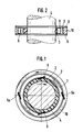
- the sealing ring suspension consists of a sealing ring 3 seated on a shaft 4 with a small sealing gap. At two opposite points, this is supported by pressure pieces 5 on a carrier ring 2.
- the support is provided with play such that a relative movement between the sealing ring 3 and carrier ring 2 is possible in the radial direction.
- the carrier ring 2 is mounted via pressure pieces 5a in the bore 1 of a housing 10.
- the pressure pieces 5 and 5a are designed as pins which allow the frictional torque that arises between the shaft 4 and the sealing ring 3 to be supported in the direction of rotation.
- the sealing ring suspension is fixed in the axial direction by two annular cover plates 6 fastened to the housing 10.
- the cover plates 6 are arranged so that the carrier ring 2 is radially, but not axially displaceable.
- the sealing ring 2 can be moved axially because of its shorter length between the cover plates 6.
- Fig. 3 shows an embodiment for a shaft 4 movable in both directions of rotation, in which 10 grooves 8 are inserted in the sealing ring 3 and the bore 1 of the enosuses, engage in the spring-like elevations 7 provided in the carrier ring 3.
- the grooves 8 in the sealing ring 3 and the bore 1 of the housing 10 can have a length in the circumferential direction such that 7 rolling elements 9 can be arranged in the grooves 8 in the direction of rotation before the spring-like elevations.
Landscapes
- Engineering & Computer Science (AREA)
- General Engineering & Computer Science (AREA)
- Mechanical Engineering (AREA)
- Sealing Devices (AREA)
- Mechanical Sealing (AREA)
- Gasket Seals (AREA)
- Sealing Using Fluids, Sealing Without Contact, And Removal Of Oil (AREA)
Abstract
Description
- Die Erfindung betrifft eine Aufhängung für einen Dichtring, der zwischen einer drehenden Welle und einer konzentrischen Bohrung mit geringem radialen Spiel der Welle angeordnet ist.
- Dichtungen werden im allgemeinen mit möglichst geringem Spiel ausgeführt, um Leckströme so gering wie möglich zu halten. Bekannt sind Dichtringe, die in Kammern (z. B. radiale Gleitringdichtungen) mit engem Spiel auf der Welle angeordnet sind und durch Abstützung an einem Festpunkt am Wegdrehen gehindert werden. Dabei tritt jedoch der Nachteil auf, daß der Dichtring sich aufgrund der einseitigen Abstützung einseitig auf der Welle einläuft und an Dichtwirkung verliert. Durch die Reaktionskräfte, zu denen auch Fliehkräfte bei der Anordnung zwischen 2 rotierenden Wellen gehören, würde der Dichtring schnell verschleißen.
- Bei Dichtungen von Turbomaschinen besteht außerdem das Problem, daß extrem kleine Montagespiele während des Betriebs vergrößert werden. Diese Spielvergrößerung entsteht durch Kontakte der Dichtelemente untereinander (z. B. Dichtung gegen Welle) oder dem Einfluß von Wärmedehnung, Mittenverlagerung von Wellen, Exzentrizitäten usw. Praktisch definieren diese Einflüsse das tatsächliche Betriebsspiel der Dichtung.
- Zwar lassen sich die durch Temperatureinflüsse hervorgerufenen Spielvergrößerungen durch geeignete Materialauswahl und thermische Behandlung von Welle und Dichtung kompensieren, jedoch gelingt dies nicht für die übrigen Effekte wie Mittenversatz der Welle, Aufschwimmen des Rotors im Lagerspiel und ähnliche dynamische Effekte.
- Aufgabe der Erfindung ist es, einen Dichtring so aufzuhängen und gegen Mitdrehen abzustützen, daß Mittenfehler aller Art durch Selbsteinstellung des Dichtringes ausgeglichen werden, ohne daß durch einseitiges Einlaufen des Dichtrings auf der Welle die Dichtwirkung nachläßt.
- Diese Aufgabe wird erfindungsgemäß dadurch gelöst, daß der Dichtring an zwei am Umfang gegenüberliegenden Stellen mit einem Trägerring und um 90° versetzt dazu auf gleiche Weise in der Bohrung eines Gehäuses oder einer zweiten konzentrischen Welle beweglich verbunden ist. Dies hat den Vorteil, daß keinerlei äußere Reaktionskräfte, die ein einseitiges Einlaufen hervorrufen könnten, auf den Dichtring wirken.
- Durch die Anordnung eines Trägerrings zwischen Dichtring und Gehäuse ist eine kräftefreie Bewegung des Dichtrings innerhalb des maximalen Mittenversatzes von Welle und Gehäuse möglich.
- Vorteilhafterweise ist der Außendurchmesser des Dichtrings dabei kleiner als der Innendurchmesser des Trägerrings und dessen Außendurchmesser kleiner als der Durchmesser der Bohrung. Auf diese Weise kann sich der Dichtring bei einem Mittenversatz der Welle kräftefrei mitbewegen, ohne daß Verschleiß fördernde Verformungen auftreten.
- Der Dichtring weist dabei vorteilhafterweise eine geringere axiale Länge auf als der Trägerring. Da beiderseits des Trägerrings ringförmige Deckplatten angeordnet sind, läßt sich der kürzere Dichtring innerhalb dieser Grenzen axial verschieben, und dieser kann einem axialen Wellenversatz folgen. Aufgrund eines axialen Druckunterschieds beidseitig der Dichtung wird zur Erzielung der Dichtwirkung der Dichtring gegen eine der ringförmigen Deckplatten gepreßt.
- In einer Ausführungsform ist die Verbindung des Dichtrings zum Trägerring über Druckstücke ausgeführt, die das zwischen Dichtring und Welle auftretende Reibmoment in Nuten abstützen. Hierdurch wird eine einfache, elastische Koppelung dieser Glieder erreicht. Auf gleiche Weise ist der Trägerring in der Bohrung befestigt.
- Die Druckstücke sind vorteilhafterweise mit etwas Spiel ausgeführt, um bei einem Mittenversatz der Welle eine spannungsfreie Abstützung zu gewährleisten.
- Vorzugsweise sind mindestens zwei Druckstücke zwischen Dichtring und Trägerring bzw. zwischen Trägerring und Bohrung vorhanden.
- Sollte die Welle in beiden Drehrichtungen beweglich sein, so kann in einer anderen Ausführungsform die Koppelung durch Nut-Feder-Verbindungen durchgeführt werden, da hierdurch eine Abstützung der Momente nach beiden Seite hin möglich ist.
- Weitere vorteilhafte Ausgestaltungen der Erfindung sind in dem Patentansprüchen 8 und 9 wiedergegeben.
- Im folgenden sind drei Ausführungsbeispiele für die Dichtringaufhängung weiter beschrieben. Dabei zeigt:
- Fig. 1 den Querschnitt einer erfindungsgemäßen Dichtringaufhängung
- Fig. 2 die gleiche Anordnung im Längsschnitt
- Fig. 3 eine Ausführung der Dichtringanordnung im Querschnitt, wobei die Druckstücke als Nut-Feder-Verbindungen ausgeführt sind,
- Fig. 4 eine Ausführung der Dichtringanordnung im Querschnitt mit in der Nut-Feder-Verbindung angeordneten Wälzkörpern.
- Die Dichtringaufhängung besteht nach Fig. 1 aus einem mit geringem Dichtspalt auf einer Welle 4 sitzenden Dichtring 3. An zwei gegenüberliegenden Stellen ist dieser durch Druckstücke 5 an einem Trägerring 2 abgestützt. Dabei ist die Abstützung derart mit Spiel versehen, daß eine Relativbewegung zwischen Dichtring 3 und Trägerring 2 in radialer Richtung möglich ist. Auf gleiche Weise um 90° versetzt dazu ist der Trägerring 2 über Druckstücke 5a in der Bohrung 1 eines Gehäuses 10 montiert. Dabei sind die Druckstücke 5 bzw. 5a als Stifte ausgeführt, welche eine Abstützung des zwischen Welle 4 und Dichtring 3 entstehenden Reibmoment in Drehrichtung zulassen.
- Wie aus Fig. 2 ersichtlich, ist die Dichtringaufhängung durch zwei am Gehäuse 10 befestigte ringförmige Deckplatten 6 in axialer Richtung festgelegt. Die Deckplatten 6 sind dabei so angeordnet, daß der Trägerring 2 radial, jedoch nicht axial verschiebbar ist. Der Dichtring 2 läßt sich wegen seiner geringeren Länge zwischen den Deckplatten 6 axial verschieben.
- Fig 3 zeigt eine Ausführung für eine in beiden Drehrichtungen bewegliche Welle 4, bei der im Dichtring 3 und der Bohrung 1 des ehäuses 10 Nuten 8 eingefügt sind, in die im Trägerring 3 angebrachte federartige Erhebungen 7 eingreifen.
- Nach Fig. 4 können die Nuten 8 im Dichtring 3 und der Bohrung 1 des Gehäuses 10 in Umfangsrichtung eine derartige Länge aufweisen, daß in Drehrichtung vor den federartigen Erhebungen 7 Wälzkörper 9 in den Nuten 8 angeordnet werden können.
Claims (9)
Priority Applications (1)
| Application Number | Priority Date | Filing Date | Title |
|---|---|---|---|
| AT87114642T ATE53441T1 (de) | 1986-10-24 | 1987-10-07 | Aufhaengung fuer einen dichtring. |
Applications Claiming Priority (2)
| Application Number | Priority Date | Filing Date | Title |
|---|---|---|---|
| DE3636165A DE3636165C1 (de) | 1986-10-24 | 1986-10-24 | Aufhaengung fuer einen Dichtring |
| DE3636165 | 1986-10-24 |
Publications (3)
| Publication Number | Publication Date |
|---|---|
| EP0264718A2 true EP0264718A2 (de) | 1988-04-27 |
| EP0264718A3 EP0264718A3 (en) | 1988-12-21 |
| EP0264718B1 EP0264718B1 (de) | 1990-06-06 |
Family
ID=6312362
Family Applications (1)
| Application Number | Title | Priority Date | Filing Date |
|---|---|---|---|
| EP87114642A Expired - Lifetime EP0264718B1 (de) | 1986-10-24 | 1987-10-07 | Aufhängung für einen Dichtring |
Country Status (5)
| Country | Link |
|---|---|
| US (1) | US4880244A (de) |
| EP (1) | EP0264718B1 (de) |
| JP (1) | JPH0814318B2 (de) |
| AT (1) | ATE53441T1 (de) |
| DE (1) | DE3636165C1 (de) |
Families Citing this family (5)
| Publication number | Priority date | Publication date | Assignee | Title |
|---|---|---|---|---|
| US5865361A (en) * | 1997-09-23 | 1999-02-02 | United States Surgical Corporation | Surgical stapling apparatus |
| US6328528B1 (en) * | 2000-04-25 | 2001-12-11 | Freudenberg-Nok General Partnership | Elastomeric pump impeller |
| FR3025854B1 (fr) * | 2014-09-11 | 2016-09-30 | Snecma | Systeme d'etancheite et turbopompe comprenant un tel systeme |
| KR102213305B1 (ko) * | 2019-08-28 | 2021-02-09 | 현대트랜시스 주식회사 | 자동변속기의 실링 어셈블리 |
| CN111799936A (zh) * | 2020-07-23 | 2020-10-20 | 佳木斯电机股份有限公司 | 一种用于电机轴的自调节动态密封装置 |
Family Cites Families (19)
| Publication number | Priority date | Publication date | Assignee | Title |
|---|---|---|---|---|
| GB1102122A (de) * | 1900-01-01 | |||
| US1359596A (en) * | 1919-12-08 | 1920-11-23 | Pressure Proof Piston Ring Com | Piston-ring |
| GB475678A (en) * | 1936-07-30 | 1937-11-24 | Gen Electric Co Ltd | Improvements in oil wipers for rotary shafts |
| US2203154A (en) * | 1937-03-05 | 1940-06-04 | Charles F Johnston | Piston ring |
| US2283056A (en) * | 1939-05-13 | 1942-05-12 | Guardiola Louis Sobrino | Piston packing |
| US3001806A (en) * | 1954-10-14 | 1961-09-26 | Macks Elmer Fred | Seal |
| US3062151A (en) * | 1957-12-31 | 1962-11-06 | Eickmann Karl | Sealing arrangement between relatively rotating parts in hydraulic and pneumatic machines, especially gas and liquid pumps and motors, internal combustion engines, hydraulic torque converters, and the like |
| US3333855A (en) * | 1964-09-22 | 1967-08-01 | Gits Bros Mfg Co | Floating controlled gap seal |
| CH450081A (de) * | 1965-07-01 | 1968-01-15 | Licentia Gmbh | Schwimmringdichtung |
| AU3731971A (en) * | 1970-12-29 | 1973-06-28 | Basil Smith Seals Limited | Mechanical seal for rotary shaft |
| US3988026A (en) * | 1976-02-27 | 1976-10-26 | Kemp Jr Dennis E | Self-compensating rotary seal member |
| GB1550293A (en) * | 1976-11-22 | 1979-08-08 | Caterpillar Tractor Co | Shaft seal |
| US4177997A (en) * | 1978-12-08 | 1979-12-11 | General Motors Corporation | Floating seal |
| US4175755A (en) * | 1978-12-11 | 1979-11-27 | Carrier Corporation | Mechanical seal assembly |
| FR2446971A1 (fr) * | 1979-01-16 | 1980-08-14 | Leonetti Bernard | Perfectionnement aux garnitures d'etancheite pour arbres tournants |
| GB2042098B (en) * | 1979-02-17 | 1983-03-09 | Rolls Royce | Seals |
| GB2131895B (en) * | 1982-12-14 | 1986-04-23 | Rolls Royce | Improvements in or relating to seals |
| JPS60159239U (ja) * | 1984-03-30 | 1985-10-23 | 三菱電機株式会社 | 磁性粒子式連結装置 |
| US4575102A (en) * | 1984-11-20 | 1986-03-11 | Ferrofluidics Corporation | Coaxial, multiple-shaft ferrofluid seal apparatus |
-
1986
- 1986-10-24 DE DE3636165A patent/DE3636165C1/de not_active Expired
-
1987
- 1987-10-07 EP EP87114642A patent/EP0264718B1/de not_active Expired - Lifetime
- 1987-10-07 AT AT87114642T patent/ATE53441T1/de not_active IP Right Cessation
- 1987-10-09 JP JP62253905A patent/JPH0814318B2/ja not_active Expired - Lifetime
-
1989
- 1989-01-19 US US07/300,731 patent/US4880244A/en not_active Expired - Fee Related
Also Published As
| Publication number | Publication date |
|---|---|
| ATE53441T1 (de) | 1990-06-15 |
| US4880244A (en) | 1989-11-14 |
| JPS63111369A (ja) | 1988-05-16 |
| EP0264718A3 (en) | 1988-12-21 |
| DE3636165C1 (de) | 1987-06-19 |
| JPH0814318B2 (ja) | 1996-02-14 |
| EP0264718B1 (de) | 1990-06-06 |
Similar Documents
| Publication | Publication Date | Title |
|---|---|---|
| DE69311512T2 (de) | Kontaktlose Wellendichtung | |
| DE69614914T2 (de) | Versplintende Lagerdichtungseinheit | |
| DE3877762T2 (de) | Gleitring-dichtung mit zentriermitteln. | |
| DE3201862C2 (de) | Berührungsfreie Dichtung | |
| DE60316320T2 (de) | Integrierte öltransferhülse und lager | |
| DE3201860C2 (de) | Berührungsfrei arbeitende Dichtung zwischen relativ zueinander umlaufenden Maschinenteilen | |
| DE3545281C2 (de) | ||
| DE202008003418U1 (de) | Doppel-Dichtungsanordnung | |
| DE3119467C2 (de) | Gleitringdichtung mit gasdynamischer Schmierung für hochtourige Strömungsmaschinen, insbesondere Gasturbinentriebwerke | |
| DE3542826C2 (de) | ||
| EP2063155A1 (de) | Vorrichtung zur Drehsicherung eines axial beweglich an einem Montagebauteil gehaltenen Gleitringes einer Gleitringdichtungsanordnung | |
| DE3321597C2 (de) | Gleitringdichtung | |
| DE2945659C2 (de) | ||
| DE1775520C3 (de) | Rotierbares Anschlußstuck | |
| EP0264718B1 (de) | Aufhängung für einen Dichtring | |
| DE69618355T2 (de) | Wellendichtung | |
| EP1902239B1 (de) | Gleitringdichtungsanordnung | |
| DE4216306A1 (de) | Drehübertrager für Druckmaschinen | |
| DE2403173A1 (de) | Wellendichtung | |
| DE19611677C2 (de) | Berührungsfreie Dichtung mit einem schwimmenden Ring | |
| EP2561256B1 (de) | Gleitringdichtung mit rotierendem gegenring mit exakt definierter einspannung | |
| EP3293426A1 (de) | Gasdichtung | |
| DE442612C (de) | Stopfbuechse fuer umlaufende Wellen von Verdichtern, insbesondere Kaeltemittel-Verdichtern | |
| DE3876705T2 (de) | Gleitlager mit zwei konzentrischen tragflaechen. | |
| DE2558463C2 (de) | Dichtungs-Halterungsanordnung |
Legal Events
| Date | Code | Title | Description |
|---|---|---|---|
| PUAI | Public reference made under article 153(3) epc to a published international application that has entered the european phase |
Free format text: ORIGINAL CODE: 0009012 |
|
| AK | Designated contracting states |
Kind code of ref document: A2 Designated state(s): AT CH FR GB IT LI NL SE |
|
| PUAL | Search report despatched |
Free format text: ORIGINAL CODE: 0009013 |
|
| AK | Designated contracting states |
Kind code of ref document: A3 Designated state(s): AT CH FR GB IT LI NL SE |
|
| 17P | Request for examination filed |
Effective date: 19890217 |
|
| 17Q | First examination report despatched |
Effective date: 19891121 |
|
| ITF | It: translation for a ep patent filed | ||
| GRAA | (expected) grant |
Free format text: ORIGINAL CODE: 0009210 |
|
| AK | Designated contracting states |
Kind code of ref document: B1 Designated state(s): AT CH FR GB IT LI NL SE |
|
| REF | Corresponds to: |
Ref document number: 53441 Country of ref document: AT Date of ref document: 19900615 Kind code of ref document: T |
|
| ET | Fr: translation filed | ||
| GBT | Gb: translation of ep patent filed (gb section 77(6)(a)/1977) | ||
| PLBE | No opposition filed within time limit |
Free format text: ORIGINAL CODE: 0009261 |
|
| STAA | Information on the status of an ep patent application or granted ep patent |
Free format text: STATUS: NO OPPOSITION FILED WITHIN TIME LIMIT |
|
| 26N | No opposition filed | ||
| ITTA | It: last paid annual fee | ||
| EAL | Se: european patent in force in sweden |
Ref document number: 87114642.9 |
|
| PGFP | Annual fee paid to national office [announced via postgrant information from national office to epo] |
Ref country code: GB Payment date: 19960916 Year of fee payment: 10 |
|
| PGFP | Annual fee paid to national office [announced via postgrant information from national office to epo] |
Ref country code: FR Payment date: 19960920 Year of fee payment: 10 Ref country code: CH Payment date: 19960920 Year of fee payment: 10 |
|
| PGFP | Annual fee paid to national office [announced via postgrant information from national office to epo] |
Ref country code: SE Payment date: 19960923 Year of fee payment: 10 Ref country code: AT Payment date: 19960923 Year of fee payment: 10 |
|
| PGFP | Annual fee paid to national office [announced via postgrant information from national office to epo] |
Ref country code: NL Payment date: 19960930 Year of fee payment: 10 |
|
| PG25 | Lapsed in a contracting state [announced via postgrant information from national office to epo] |
Ref country code: GB Free format text: LAPSE BECAUSE OF NON-PAYMENT OF DUE FEES Effective date: 19971007 Ref country code: AT Free format text: LAPSE BECAUSE OF NON-PAYMENT OF DUE FEES Effective date: 19971007 |
|
| PG25 | Lapsed in a contracting state [announced via postgrant information from national office to epo] |
Ref country code: SE Free format text: LAPSE BECAUSE OF NON-PAYMENT OF DUE FEES Effective date: 19971008 |
|
| PG25 | Lapsed in a contracting state [announced via postgrant information from national office to epo] |
Ref country code: LI Free format text: LAPSE BECAUSE OF NON-PAYMENT OF DUE FEES Effective date: 19971031 Ref country code: FR Free format text: THE PATENT HAS BEEN ANNULLED BY A DECISION OF A NATIONAL AUTHORITY Effective date: 19971031 Ref country code: CH Free format text: LAPSE BECAUSE OF NON-PAYMENT OF DUE FEES Effective date: 19971031 |
|
| PG25 | Lapsed in a contracting state [announced via postgrant information from national office to epo] |
Ref country code: NL Free format text: LAPSE BECAUSE OF NON-PAYMENT OF DUE FEES Effective date: 19980501 |
|
| GBPC | Gb: european patent ceased through non-payment of renewal fee |
Effective date: 19971007 |
|
| REG | Reference to a national code |
Ref country code: CH Ref legal event code: PL |
|
| NLV4 | Nl: lapsed or anulled due to non-payment of the annual fee |
Effective date: 19980501 |
|
| EUG | Se: european patent has lapsed |
Ref document number: 87114642.9 |
|
| REG | Reference to a national code |
Ref country code: FR Ref legal event code: ST |
|
| PG25 | Lapsed in a contracting state [announced via postgrant information from national office to epo] |
Ref country code: IT Free format text: LAPSE BECAUSE OF NON-PAYMENT OF DUE FEES;WARNING: LAPSES OF ITALIAN PATENTS WITH EFFECTIVE DATE BEFORE 2007 MAY HAVE OCCURRED AT ANY TIME BEFORE 2007. THE CORRECT EFFECTIVE DATE MAY BE DIFFERENT FROM THE ONE RECORDED. Effective date: 20051007 |