EP0263848B1 - Kapazitiver chemischer fühler zur feststellung gewisser analyte, unter anderem von kohlenwasserstoff in flüssigen medien - Google Patents
Kapazitiver chemischer fühler zur feststellung gewisser analyte, unter anderem von kohlenwasserstoff in flüssigen medien Download PDFInfo
- Publication number
- EP0263848B1 EP0263848B1 EP87901929A EP87901929A EP0263848B1 EP 0263848 B1 EP0263848 B1 EP 0263848B1 EP 87901929 A EP87901929 A EP 87901929A EP 87901929 A EP87901929 A EP 87901929A EP 0263848 B1 EP0263848 B1 EP 0263848B1
- Authority
- EP
- European Patent Office
- Prior art keywords
- capacitor
- concentrating
- liquid medium
- sensor
- capacitance
- Prior art date
- Legal status (The legal status is an assumption and is not a legal conclusion. Google has not performed a legal analysis and makes no representation as to the accuracy of the status listed.)
- Expired
Links
- 229930195733 hydrocarbon Natural products 0.000 title claims abstract description 64
- 150000002430 hydrocarbons Chemical class 0.000 title claims abstract description 60
- 239000007788 liquid Substances 0.000 title claims abstract description 43
- 239000000126 substance Substances 0.000 title description 12
- 239000003990 capacitor Substances 0.000 claims abstract description 74
- 239000012491 analyte Substances 0.000 claims abstract description 43
- 239000004215 Carbon black (E152) Substances 0.000 claims abstract description 41
- 230000015572 biosynthetic process Effects 0.000 claims abstract description 23
- 230000007423 decrease Effects 0.000 claims abstract description 18
- 230000004044 response Effects 0.000 claims abstract description 8
- 239000000463 material Substances 0.000 claims description 36
- 229920002379 silicone rubber Polymers 0.000 claims description 25
- 239000004945 silicone rubber Substances 0.000 claims description 24
- 239000004020 conductor Substances 0.000 claims description 10
- 230000008859 change Effects 0.000 claims description 9
- 238000000576 coating method Methods 0.000 claims description 9
- 239000011248 coating agent Substances 0.000 claims description 8
- 238000005259 measurement Methods 0.000 claims description 7
- 239000012528 membrane Substances 0.000 claims description 7
- 238000012360 testing method Methods 0.000 claims description 7
- 150000003839 salts Chemical class 0.000 claims description 6
- 150000002632 lipids Chemical class 0.000 claims description 5
- 239000012777 electrically insulating material Substances 0.000 claims description 4
- 230000001681 protective effect Effects 0.000 claims description 3
- 229920000181 Ethylene propylene rubber Polymers 0.000 claims description 2
- VHOQXEIFYTTXJU-UHFFFAOYSA-N Isobutylene-isoprene copolymer Chemical compound CC(C)=C.CC(=C)C=C VHOQXEIFYTTXJU-UHFFFAOYSA-N 0.000 claims description 2
- 239000002174 Styrene-butadiene Substances 0.000 claims description 2
- MTAZNLWOLGHBHU-UHFFFAOYSA-N butadiene-styrene rubber Chemical compound C=CC=C.C=CC1=CC=CC=C1 MTAZNLWOLGHBHU-UHFFFAOYSA-N 0.000 claims description 2
- 229920000058 polyacrylate Polymers 0.000 claims description 2
- 229920002635 polyurethane Polymers 0.000 claims description 2
- 239000004814 polyurethane Substances 0.000 claims description 2
- 239000004065 semiconductor Substances 0.000 claims description 2
- 239000011115 styrene butadiene Substances 0.000 claims description 2
- 229920003048 styrene butadiene rubber Polymers 0.000 claims description 2
- XLYOFNOQVPJJNP-UHFFFAOYSA-N water Substances O XLYOFNOQVPJJNP-UHFFFAOYSA-N 0.000 abstract description 31
- 230000005684 electric field Effects 0.000 abstract description 11
- UHOVQNZJYSORNB-UHFFFAOYSA-N Benzene Chemical compound C1=CC=CC=C1 UHOVQNZJYSORNB-UHFFFAOYSA-N 0.000 description 24
- VLKZOEOYAKHREP-UHFFFAOYSA-N n-Hexane Chemical compound CCCCCC VLKZOEOYAKHREP-UHFFFAOYSA-N 0.000 description 22
- 239000000243 solution Substances 0.000 description 20
- OFBQJSOFQDEBGM-UHFFFAOYSA-N Pentane Chemical compound CCCCC OFBQJSOFQDEBGM-UHFFFAOYSA-N 0.000 description 16
- IMNFDUFMRHMDMM-UHFFFAOYSA-N N-Heptane Chemical compound CCCCCCC IMNFDUFMRHMDMM-UHFFFAOYSA-N 0.000 description 15
- 230000007246 mechanism Effects 0.000 description 15
- 239000000758 substrate Substances 0.000 description 9
- XDTMQSROBMDMFD-UHFFFAOYSA-N Cyclohexane Chemical compound C1CCCCC1 XDTMQSROBMDMFD-UHFFFAOYSA-N 0.000 description 8
- 238000000034 method Methods 0.000 description 7
- 239000003994 anesthetic gas Substances 0.000 description 6
- 239000007864 aqueous solution Substances 0.000 description 6
- 230000007613 environmental effect Effects 0.000 description 6
- 239000000203 mixture Substances 0.000 description 6
- 238000010586 diagram Methods 0.000 description 5
- 239000012153 distilled water Substances 0.000 description 5
- 239000012530 fluid Substances 0.000 description 5
- 239000007789 gas Substances 0.000 description 5
- 239000003921 oil Substances 0.000 description 5
- -1 acyclic hydrocarbons Chemical class 0.000 description 4
- 238000000151 deposition Methods 0.000 description 4
- 239000002245 particle Substances 0.000 description 4
- 230000008569 process Effects 0.000 description 4
- 230000035945 sensitivity Effects 0.000 description 4
- KFZMGEQAYNKOFK-UHFFFAOYSA-N Isopropanol Chemical compound CC(C)O KFZMGEQAYNKOFK-UHFFFAOYSA-N 0.000 description 3
- YXFVVABEGXRONW-UHFFFAOYSA-N Toluene Chemical compound CC1=CC=CC=C1 YXFVVABEGXRONW-UHFFFAOYSA-N 0.000 description 3
- 239000012141 concentrate Substances 0.000 description 3
- 238000006073 displacement reaction Methods 0.000 description 3
- 239000003673 groundwater Substances 0.000 description 3
- 239000011810 insulating material Substances 0.000 description 3
- 239000011159 matrix material Substances 0.000 description 3
- 230000006911 nucleation Effects 0.000 description 3
- 238000010899 nucleation Methods 0.000 description 3
- 229920000642 polymer Polymers 0.000 description 3
- CSCPPACGZOOCGX-UHFFFAOYSA-N Acetone Chemical compound CC(C)=O CSCPPACGZOOCGX-UHFFFAOYSA-N 0.000 description 2
- RYGMFSIKBFXOCR-UHFFFAOYSA-N Copper Chemical compound [Cu] RYGMFSIKBFXOCR-UHFFFAOYSA-N 0.000 description 2
- FAPWRFPIFSIZLT-UHFFFAOYSA-M Sodium chloride Chemical compound [Na+].[Cl-] FAPWRFPIFSIZLT-UHFFFAOYSA-M 0.000 description 2
- 238000001311 chemical methods and process Methods 0.000 description 2
- 229910052802 copper Inorganic materials 0.000 description 2
- 239000010949 copper Substances 0.000 description 2
- 125000000753 cycloalkyl group Chemical group 0.000 description 2
- 230000008021 deposition Effects 0.000 description 2
- 238000005137 deposition process Methods 0.000 description 2
- 230000000694 effects Effects 0.000 description 2
- 239000003344 environmental pollutant Substances 0.000 description 2
- 238000002474 experimental method Methods 0.000 description 2
- 230000004907 flux Effects 0.000 description 2
- 230000002209 hydrophobic effect Effects 0.000 description 2
- 239000012212 insulator Substances 0.000 description 2
- 238000012986 modification Methods 0.000 description 2
- 230000004048 modification Effects 0.000 description 2
- 231100000719 pollutant Toxicity 0.000 description 2
- 229920000052 poly(p-xylylene) Polymers 0.000 description 2
- 239000004417 polycarbonate Substances 0.000 description 2
- 229920000515 polycarbonate Polymers 0.000 description 2
- 239000011148 porous material Substances 0.000 description 2
- 239000002904 solvent Substances 0.000 description 2
- 238000007738 vacuum evaporation Methods 0.000 description 2
- LFQSCWFLJHTTHZ-UHFFFAOYSA-N Ethanol Chemical compound CCO LFQSCWFLJHTTHZ-UHFFFAOYSA-N 0.000 description 1
- XUIMIQQOPSSXEZ-UHFFFAOYSA-N Silicon Chemical compound [Si] XUIMIQQOPSSXEZ-UHFFFAOYSA-N 0.000 description 1
- PNEYBMLMFCGWSK-UHFFFAOYSA-N aluminium oxide Inorganic materials [O-2].[O-2].[O-2].[Al+3].[Al+3] PNEYBMLMFCGWSK-UHFFFAOYSA-N 0.000 description 1
- 230000003444 anaesthetic effect Effects 0.000 description 1
- 230000003466 anti-cipated effect Effects 0.000 description 1
- 239000012620 biological material Substances 0.000 description 1
- 238000006243 chemical reaction Methods 0.000 description 1
- 150000001875 compounds Chemical class 0.000 description 1
- 239000000470 constituent Substances 0.000 description 1
- 239000010779 crude oil Substances 0.000 description 1
- 230000003247 decreasing effect Effects 0.000 description 1
- 238000013461 design Methods 0.000 description 1
- 238000001514 detection method Methods 0.000 description 1
- JPGQOUSTVILISH-UHFFFAOYSA-N enflurane Chemical compound FC(F)OC(F)(F)C(F)Cl JPGQOUSTVILISH-UHFFFAOYSA-N 0.000 description 1
- 229960000305 enflurane Drugs 0.000 description 1
- 238000011067 equilibration Methods 0.000 description 1
- 238000005530 etching Methods 0.000 description 1
- 230000005669 field effect Effects 0.000 description 1
- 239000000446 fuel Substances 0.000 description 1
- 239000011521 glass Substances 0.000 description 1
- PCHJSUWPFVWCPO-UHFFFAOYSA-N gold Chemical compound [Au] PCHJSUWPFVWCPO-UHFFFAOYSA-N 0.000 description 1
- 229910052737 gold Inorganic materials 0.000 description 1
- 239000010931 gold Substances 0.000 description 1
- BCQZXOMGPXTTIC-UHFFFAOYSA-N halothane Chemical compound FC(F)(F)C(Cl)Br BCQZXOMGPXTTIC-UHFFFAOYSA-N 0.000 description 1
- 229960003132 halothane Drugs 0.000 description 1
- 239000001257 hydrogen Substances 0.000 description 1
- 229910052739 hydrogen Inorganic materials 0.000 description 1
- 230000010355 oscillation Effects 0.000 description 1
- 230000010363 phase shift Effects 0.000 description 1
- 238000005381 potential energy Methods 0.000 description 1
- 238000012545 processing Methods 0.000 description 1
- 230000029058 respiratory gaseous exchange Effects 0.000 description 1
- 238000012552 review Methods 0.000 description 1
- 229920006395 saturated elastomer Polymers 0.000 description 1
- 239000013049 sediment Substances 0.000 description 1
- 229910052710 silicon Inorganic materials 0.000 description 1
- 239000010703 silicon Substances 0.000 description 1
- 239000011780 sodium chloride Substances 0.000 description 1
- 230000008961 swelling Effects 0.000 description 1
- 230000007704 transition Effects 0.000 description 1
- 235000012431 wafers Nutrition 0.000 description 1
Images

Classifications
-
- G—PHYSICS
- G01—MEASURING; TESTING
- G01N—INVESTIGATING OR ANALYSING MATERIALS BY DETERMINING THEIR CHEMICAL OR PHYSICAL PROPERTIES
- G01N33/00—Investigating or analysing materials by specific methods not covered by groups G01N1/00 - G01N31/00
- G01N33/18—Water
- G01N33/1826—Organic contamination in water
- G01N33/1833—Oil in water
-
- G—PHYSICS
- G01—MEASURING; TESTING
- G01N—INVESTIGATING OR ANALYSING MATERIALS BY DETERMINING THEIR CHEMICAL OR PHYSICAL PROPERTIES
- G01N27/00—Investigating or analysing materials by the use of electric, electrochemical, or magnetic means
- G01N27/02—Investigating or analysing materials by the use of electric, electrochemical, or magnetic means by investigating impedance
- G01N27/22—Investigating or analysing materials by the use of electric, electrochemical, or magnetic means by investigating impedance by investigating capacitance
- G01N27/227—Sensors changing capacitance upon adsorption or absorption of fluid components, e.g. electrolyte-insulator-semiconductor sensors, MOS capacitors
Definitions
- the present invention relates to a capacitive sensor that may be used to detect small traces of hydrocarbon molecules, and other selected analytes, in liquid medium.
- the uses of the invented sensor would include, but are not limited to: detecting trace hydrocarbon pollutants in ground water or streams; oil exploration; and, detecting trace substances in industrial and laboratory processes.
- GB-A-2 136 130 discloses an arrangement for sensing a particular chemical reaction by applying a coating of reactive material above or adjacent to a capacitor having a series of electrodes.
- the reactive material or layer may be biologically active in which case the arrangement may be used for sensing biological material which would react with the reactive layer.
- US-A-4 571 543 discloses a device to sense the concentration of a non-aqueous particle or gas. The device may use a capacitor having a silicon rubber layer which swells in the presence of a particle gas.
- the present invention is a new sensor for determining the presence of trace analytes, such as hydrocarbons, in a liquid medium.
- the invention uses a unique mechanism that produces nucleated bubbles in the liquid medium adjacent to the surface of a concentrating layer. The formation of such nucleated bubbles in the liquid layer adjacent to the concentrating layer lowers the measured capacitance of the sensor. This mechanism provides high sensitivity to trace hydrocarbon or other selected analytes in solution.
- the invention utilizes an "open" or planar capacitor which comprises: a first and second conductor or electrode positioned on a substrate and disposed a distance from each other to form a channel; a first electrically insulating layer that covers the conductors; and, an active or concentrating layer, that has a high affinity for non-polar molecules, which then coats the two insulated conductors and may fill a portion of the channel formed between the electrodes.
- an alternating voltage is applied across the conductors, an electric field is generated having lines of flux that cross the channel and bridge the volume between the conductors.
- the surface of the "open" capacitor is exposed to a liquid medium containing hydrocarbons, or other selected analyte molecules.
- the capacitive sensor When the capacitive sensor is exposed to such a liquid medium, the capacitance of the sensor decreases as the concentration of the analyte increases.
- Applicants have observed two different classes of response from hydrocarbon analytes in an aqueous solution.
- the first observed class produces a rapid decrease in capacitance as the concentration of certain acyclic hydrocarbons increases.
- a unique bubble generating mechanism accounts for the extreme sensitivity of the sensor. It has been found that bubbles nucleate in the liquid medium on the surface of the concentrating layer in proportion to the concentration of the analyte. The nucleated bubbles, which have a dielectric constant of 1-3, form on the interface between the liquid medium and the concentrating layer. Formation of these bubbles displaces water molecules, which have a dielectric constant approximately equal to or greater than 78, from the sensor's electric field. This modification to the dielectric properties of the environmental liquid layer adjacent to the sensor causes a significant decrease in the capacitance of the sensor. Applicants discovered that non-polar molecules with a high Henry's Law constant, such as acyclic hydrocarbons, will produce nucleated bubbles even when the analyte is in relatively low concentrations.
- a second observed class did not produce the nucleated bubbles. However, a smaller, but measurable, decrease in a capacitance was still observed with increasing analyte concentration. Analytes that did not produce nucleated bubbles, are in a class of non-polar molecules having low Henry's Law constant, such as cyclic hydrocarbons. The measurable decrease in capacitance is believed due to physical displacement of higher dielectric water molecules from the sensor's electric field.
- the present invention also teaches a differential sensor embodiment comprising an affinity sensor, as described above, with a reference capacitor sensor.
- the accuracy of the present invention is increased if differential sensing is employed.
- the reference capacitor compensates for changes in the dielectric constant of the liquid medium caused by changes in temperature, ionic concentration and the physical and chemical state of the liquid medium.
- a first embodiment of the present invention is a sensor capable of detecting trace amounts of hydrocarbons, or other selected analytes, in a liquid medium.
- a further embodiment is the use of a concentrating and nucleating layer to coat an "open" or planar capacitor, thereby causing the formation of nucleated bubbles in the fluid medium adjacent to that layer.
- the nucleated bubbles cause a dramatic decrease in capacitance with increasing analyte concentration.
- a further embodiment is a sensor that provides an extremely sensitive response to solutions containing analytes that have non-polar molecules with high Henry's Law constant, such as acyclic hydrocarbons.
- a further embodiment is a concentrating and nucleating layer made from selected polymeric materials having a high affinity to non-polar molecules (such as silicone rubber), and lipid materials.
- a further embodiment is to detect an analyte in a liquid medium using a mechanism that displaces water molecules from the sensor's electrical field in proportion to analyte concentration.
- a further embodiment is the use of a differential sensor having an analyte affinity sensor and a reference capacitor sensor.
- the reference capacitor sensor compensates for changes in the dielectric constant of the liquid medium caused by changes in ionic concentration and other physical or chemical states of the liquid medium.
- a further embodiment involves presoaking the sensor with a salt matrix solution similar to that anticipated in the environment, to speed equilibration.
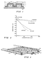
- Figure 1 is a schematic cross-sectional view of the capacitive sensor for detecting hydrocarbons, and other selected analytes, in a liquid medium.
- Figure 2 is a graph showing the change in capacitance of the sensor for increasing concentration of various hydrocarbon analytes.
- Figure 3 is a perspective view of an "open" capacitor that uses a plurality of interdigitated fingers.
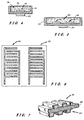
- Figure 4 is a schematic cross-sectional view of the analyte sensor positioned in a protective casing.
- Figure 5 is a schematic cross-sectional view of a differential capacitive sensor comprising an analyte capacitor sensor and a reference capacitor sensor.
- Figure 6 is an embodiment of the differential capacitive sensor having the affinity capacitor and the reference capacitor located side by side.
- Figure 7 is an embodiment of the differential capacitive sensor having the affinity capacitor and the reference capacitor located back to back.
- Figure 8 is a schematic diagram of a circuit to detect the phase difference between the affinity capacitor and the reference capacitor.
- Figure 9 is a schematic diagram of a microprocessor system for use with a differential affinity sensor that has an affinity capacitor and a reference capacitor.
- Figure 1 is a schematic cross-sectional view showing the general configuration of the capacitive chemical sensor.
- a first conductor 10 and a second conductor 12 are positioned on the surface of an insulating material or substrate 14.
- a first layer containing an electrically insulating material 16 coats the two electrodes.
- a active layer 18 also coats the two electrodes and may partially fill the channel formed between the two electrodes.
- the material for the active layer 18 is selected to have a relatively high affinity for non-polar molecules. As will be described later in the specification, various polymeric coatings such as silicone rubber have a high affinity for non-polar hydrocarbon molecules.
- the resulting structure forms an "open" or planar capacitor that is directly exposed to a liquid medium containing selected non-polar analyte molecules in solution.
- a liquid medium containing selected non-polar analyte molecules in solution.
- the capacitance of the sensor decreases as the concentration of the analyte molecules increases.
- the graph of Figure 2 outlines experimental results using the invented sensor. The graph shows the inverse relationship between the measured capacitance of the sensor with increasing concentration of the hydrocarbon analyte in a fluid medium. The following experimental procedure was used to obtain these results.
- the graph of Figure 2 demonstrates that the capacitance of the sensor decreases with increasing concentration of the following hydrocarbons: cyclohexane, benzene, pentane, hexane and heptane.
- the capacitance decreased more drastically than with cyclohexane and benzene.
- the bubble formation was proportional to hydrocarbon concentration.
- Applicants also observed that when the nucleated bubbles were removed by vibration or physical scrapping, they returned rapidly and the measured capacitance returned to the expected value.
- the non-polar hydrocarbon molecules will preferentially enter the silicone rubber layer than be in the aqueous solution because of the high affinity of silicone rubber for non-polar molecules.
- the actual energy for this process comes from the attempt by water molecules to lower their potential energy by expelling the hydrocarbon molecules that separate the polar water molecules.
- the silicone rubber layer acts to absorb and concentrate hydrocarbon molecules from the solution.
- the first mechanism (which appears to dominate with acyclic hydrocarbons such as pentane, hexane and heptane) produces nucleated bubbles on the surface of the silicone rubber layer. The formation of nucleated bubbles on the surface of the silicone rubber layer produces high sensitivity of the sensor to these particular hydrocarbon molecules.
- the degree of bubble formation increases as the total amount of hydrocarbon molecules in the liquid increase. It is estimated that the dielectric constant of the aqueous solution is approximately 78 or greater, and the dielectric constant of the bubbles is approximately 1-3. Therefore, formation of the bubbles displaces aqueous solution, and lowers the dielectric constant in the electric field of the capacitor (see generally, element 20, Figure 1). Lowering the dielectric constant in the area of electric field causes a decrease in capacitance.
- the lowest energy way to accommodate the presence of the non-polar molecules is to concentrate them in as small a volume as possible.
- the hydrocarbon molecules are "squeezed" into the silicone rubber. This process results in high concentration of hydrocarbon molecules in the vicinity of the silicone rubber/water interface.
- the amount of hydrocarbon squeezed into this space exceeds the solubility of the material in water, a phase transition can take place and a bubble can be formed.
- the presence of irregularities in the silicone rubber layer probably help to nucleate the formation of the bubbles.
- the presence and degree of bubble formation can be related to Henry's Law constant for the particular hydrocarbon or other analyte material.
- the Henry's Law constant is thus a measure of how poorly the solute is tolerated by the solvent.
- nucleated bubbles are expected for hydrocarbon analytes having relatively large Henry's Law constant.
- hydrocarbons that produce nucleated bubbles such as pentane, hexane and heptane
- have Henry's Laws constant that ranged from 125-230; however, hydrocarbons that did not exhibit bubble formation or exhibited low bubble formation, such as cyclohexane and benzene, had Henry's Law constants ranging from 0.5 to 18.
- This highly sensitive bubble formation mechanism enables the invented sensor to detect non-polar molecules having relatively large Henry's Law constants.
- Figure 3 is a perspective view of a planar capacitor having a plurality of interdigitated fingers.
- Metallic electrodes or conductors 24 and 26 are positioned on an insulating substrate 28.
- Each electrode has a plurality of fingers that are disposed in an interdigitated manner relative to the fingers of the other electrodes.
- the interdigitated fingers from both electrodes form a plurality of channels.
- Known photolithographic etching techniques are used to form the interdigitated fingers on a substrate.
- the substrate can be made from insulating material such as Corning 7059 glass or alumina wafers.
- the interdigitated fingers can be made of copper and/or gold. Applicants selected 2 mil wide fingers that are approximately 1 mil high and separated by 3 mil spaces, although other dimensions may be used.
- the interdigitated fingers are covered with an insulating layer 30.
- Applicants made the insulating layer 30 with a 1-2.5 micron coating of parylene polymer deposited using known deposition processes and a 0.3 micron of SiO deposited using vapor vacuum evaporation deposition; however, alternative electrical insulating material can be used.
- a second layer of a material that has a high affinity for non-polymer molecules coats the insulating layer 30.
- the second, or active layer 18 is best shown in Figure 1.
- this second layer can be made from various polymeric materials such as silicone rubber, as well as the following non-limiting materiais: polyurethane, ethylene propylene rubber, styrene butadiene, polyacrylate, isobutylene isoprene and various lipid materials. Liquid to be tested for a particular analyte is brought into contact with the planar capacitor as discussed earlier. It is to be understood that other geometries of the planar capacitor can provide the desired feature of the open capacitor.
- the electrode elements of the capacitor can be interleaved on the substrate or, parallel electrode elements can be embedded in a molded insulator with the active layer coating the molded insulator.
- the electrode elements 24 and 26 of the capacitor can be made from doped semiconductor materials, such as doped silicon.
- the sensor was described detecting hydrocarbons, other analytes can be detected.
- the bubble mechanism would detect most non-polar molecules having a relatively large Henry's Law constant.
- the liquid medium has been described in terms of distilled water, any aqueous solution would work. Applicants ran tests with sodium chloride aqueous solutions and found satisfactory detection of the hydrocarbon analytes. It is also to be understood that the liquid medium may be non-aqueous liquids.
- FIG. 4 is a schematic representation of the sensor that is packaged for use as an environmental sensor.
- the planar capacitor 32 (designed in accordance with this specification) is securely fixed in a casing 34.
- a membrane 36 allows solutions to enter the interior of the casing from the environment and to contact the sensor 32.
- the membrane 36 protects the sensor from abrasive particles in the environment.
- a polycarbonate sheet with about .2 micron etched pores is suggested for the membrane.
- the sensor and casing can be presoaked in a salt matrix solution 38 similar to solutions found in the test environment. Such presoaking would be advantageous to reduce the time to equilibrate to new salt concentrations.
- a vibrator 40 such as piezoelectric oscillator is used to periodically shake nucleated bubbles from the sensor. This feature would increase the dynamic response of the sensor and allow continuous or time trend measurements.
- FIG. 5 is a schematic representation of a differential sensor embodiment that includes both the analyte sensor 32 and a reference capacitor 42.
- the accuracy of the present invention is increased if differential sensing is used.
- the reference capacitor 42 compensates for changes in the dielectric constant of the liquid medium caused by changes in temperature, ionic concentration, pH, composition and the physical and chemical state of a liquid medium.
- the reference capacitor 42 is identical in design to the sensor capacitor, except the second or concentrating layer is not used. Therefore, the reference capacitor comprises two electrodes positioned on a substrate coated with an insulating layer to form a capacitor.
- the analyte sensor 32 and the reference capacitor sensor 42 are mounted within casing 44.
- a membrane 46 allows solutions to enter the interior of the casing from the environment and to contact both analyte sensor 32 and the reference capacitor sensor 42.
- the membrane 46 protects the sensor from abrasive particles in the environment and can be made from a polycarbonate sheet with .2 micron etched pores.
- the analyte sensor and casing can be presoaked in a salt matrix solution 48, similar to the solutions found in the test environment. As discussed previously, such presoaking enables the sensor to be sold in a state equilibrated to expected environmental salt concentrations.
- a vibrator 50 such as a piezoelectric oscillator, can be used periodically to shake nucleated bubbles free from the analyte sensor. This allows the sensor to make accurate continuous or time trend measurements.
- Figures 6 and 7 various embodiments for a differential sensor that includes an analyte sensor 32 and reference capacitor sensor 42.
- Figure 6 is a top view of the analyte sensor 32 and reference capacitor 42 located side by side on the same substrate.
- Figure 7 is a cross-sectional view of the analyte sensor 32 and reference capacitor 42 located back to back.
- a shield 52 located between the capacitors can be used to isolate the electric field generated by each capacitor.
- the fluid medium under test would be simultaneously introduced onto both the sensor capacitor and reference capacitor.
- the analyte sensor shown in Figures 7 and 8 do not show the second layer of polymeric material which covers the insulating layers.
- Figures 8 and 9 are schematic diagrams which illustrate two possible circuits to be used with a differential sensors as taught by the present invention.
- Figure 8 is a schematic diagram of the circuit to detect the phase difference between the analyte sensor 32 and reference capacitor 42.
- the stable oscillator 54 supplies an alternating signal to the analyte capacitor 32 and the reference capacitor 42. These capacitors are placed in parallel with trim capacitors 56 and 58.
- Phase detector 60 detects the phase angle shift between the analyte capacitor 32 and the reference capacitor 42. The phase shift is functionally related to the analyte concentration in the fluid medium.
- FIG 9 is a schematic diagram of a microprocessor system for use with a differential sensor.
- the system contains an analyte capacitor 32 and reference capacitor 42.
- the analyte and reference capacitors (32, 42) are brought into contact with the liquid medium under test.
- Each capacitor is connected to an oscillator (62, 64) and a change in the capacitance will alter the frequency of oscillation of its associated oscillator.
- the output frequency of each oscillator (62, 64) is fed to an associated counter (66, 68) which sends the frequency count in digital form via bus 70 to microprocessor 72.
- a look-up table containing data similar to that shown in Figure 2 is stored in the microcomputer and a determination of the concentration of the analyte in the fluid medium is made. This value is displayed on output display 74. It is to be understood that other circuits can also be envisioned once one understands the differential change in capacitance between the analyte capacitor and the reference capacitor as taught by the present invention.
- the capacitive chemical sensor may be integrated with measurement and signal processing electronics to form either a monolithic integrated circuit chip or hybrid circuit.
- the capacitive chemical sensor could be integrated in the gate circuit of a field effect transistor (FET) to yield a "floating gate” FET configuration.
- FET field effect transistor
Landscapes
- Chemical & Material Sciences (AREA)
- Health & Medical Sciences (AREA)
- Life Sciences & Earth Sciences (AREA)
- Immunology (AREA)
- Pathology (AREA)
- Physics & Mathematics (AREA)
- Engineering & Computer Science (AREA)
- General Physics & Mathematics (AREA)
- Analytical Chemistry (AREA)
- Biochemistry (AREA)
- General Health & Medical Sciences (AREA)
- Power Engineering (AREA)
- Chemical Kinetics & Catalysis (AREA)
- Electrochemistry (AREA)
- Food Science & Technology (AREA)
- Medicinal Chemistry (AREA)
- Investigating Or Analyzing Materials By The Use Of Electric Means (AREA)
- Investigating Or Analyzing Non-Biological Materials By The Use Of Chemical Means (AREA)
Claims (22)
- Vorrichtung vom Kapazitätsmessungstyp zum Messen eines ausgewählten Analyten in einem flüssigen Medium, welche eine auf die Anwesenheit eines ausgewählten Analyten in dem flüssigen Medium ansprechende Einrichtung (10, 12) besitzt, dadurch gekennzeichnet, daß die Vorrichtung weiterhin ein konzentrierendes und keimbildendes Material (18) einschließt, welches geeignet ist, einem in Untersuchung befindlichen flüssigen Medium ausgesetzt zu werden, um eine durch Keime bewirkte Blasenbildung in einem flüssigen Medium entsprechend einem in dem flüssigen Medium enthaltenen ausgewählten Analyt auf einer Oberfläche des Materials hervorzurufen, und weiter dadurch gekennzeichnet, daß die ansprechende Einrichtung in Verbindung mit der konzentrierenden und keimbildenden Einrichtung angebracht ist und auf die Bildung der Blasen anspricht.
- Vorrichtung von Anspruch 1, wobei die ansprechende Einrichtung ein Kondensator (10, 12) ist und wobei die Blasenbildung mit zunehmender Analyt-Konzentration eine Änderung der Kapazität bewirkt.
- Vorrichtung von Anspruch 1, wobei die ansprechende Einrichtung ein Kondensator ist, welcher wenigstens ein Paar räumlich voneinander getrennter Elektroden-Elemente (10, 12) besitzt, und worin die Blasenbildung mit zunehmender Analyt-Konzentration eine Abnahme der Kapazität bewirkt.
- Vorrichtung von Anspruch 1 oder 3, wobei das konzentrierende und keimbildende Material (18) ein Material ist, welches eine Affinität zu nichtpolaren Molekülen besitzt, wobei nichtpolare Analyt-Moleküle mit einer hohen Konstante nach Henrys Gesetz in dem flüssigen Medium auf der Oberfläche des Materials zur Keimbildung neigen.
- Vorrichtung von Anspruch 1 oder 3, wobei das konzentrierende und keimbildende Material (18) aus der aus Polymer- und Lipidmaterialien mit hoher Affinität zu nichtpolaren Molekülen bestehenden Gruppe ausgewählt ist.
- Vorrichtung von Anspruch 1 oder 3, wobei das konzentrierende und keimbildende Material (18) aus der aus Polyurethan, Ethylenpropylen-Gummi, Styrol-Butadien, Polyacrylat, Silikon-Gummi und Isobutylen-Isopren bestehenden Gruppe ausgewählt ist.
- Vorrichtung von Anspruch 1 oder 3, wobei das konzentrierende und keimbildende Material (18) Silikon-Gummi ist.
- Vorrichtung von Anspruch 3, wobei die Elektrodenelemente (10, 12) aus dotiertem Halbleiter-Material gefertigt sind.
- Vorrichtung von Anspruch 3, wobei die Elektrodenelemente (10, 12) aus elektrisch leitendem Material gefertigt sind.
- Vorrichtung von Anspruch 3, welche weiterhin eine elektronische Einrichtung (72, 74) umfaßt, die zum Messen und Anzeigen der Kapazitätsänderungen steuerbar an den Kondensator gekoppelt ist.
- Vorrichtung von Anspruch 3, wobei ein elektrisch isolierendes Material (16) das wenigstens eine Paar Elektrodenelemente (10, 12) von dem konzentrierenden und keimbildenden Material (18) trennt.
- Vorrichtung von Anspruch 11, wobei das elektrisch isolierende Material (16) eine erste Schicht bildet, welche wenigstens einen Teil der Elektrodenelemente überzieht und worin das konzentrierende und keimbildende Material (18) eine zweite Schicht bildet, welche wenigstens einen Teil der ersten Schicht überzieht.
- Vorrichtung von Anspruch 12, wobei das wenigstens eine Paar räumlich getrennter Elektrodenelemente (10, 12) einen Tunnel dazwischen bildet und wobei das konzentrierende und keimbildende Material (18) wenigstens einen Teil des Tunnels ausfüllt.
- Vorrichtung von Anspruch 1, wobei das konzentrierende und keimbildende Material (18) ein Polymermaterial mit einer hohen Affinität zu Kohlenwasserstoff-Molekülen ist.
- Vorrichtung von Anspruch 1, welche weiterhin eine Einrichtung (40) zum periodischen Schütteln des konzentrierenden und keimbildenden Materials umfaßt, wodurch Blasen von der Oberfläche des konzentrierenden und keimbildenden Materials entfernt werden, um dem Meßfühler zu gestatten, fortlaufende Messungen der Kohlenwasserstoffkonzentration vorzunehmen.
- Vorrichtung von Anspruch 3, wobei der Kondensator in einem Schutzbehälter (34) angebracht ist, und wobei ein Abschnitt des Behälters eine poröse Membrane (36) enthält, welche Flüssigkeit in den Behälter eindringen läßt.
- Vorrichtung von Anspruch 3, wobei das konzentrierende und keimbildende Material quillt, wenn es Moleküle des ausgewählten Analyts absorbiert, und dadurch Moleküle des flüssigen Mediums aus dem Kondensator benachbarten Bereichen verdrängt.
- Vorrichtung von Anspruch 1, wobei die ansprechende Einrichtung ein erster Kondensator (32) ist, welcher wenigstens ein Paar räumlich getrennter Elektrodenelemente (10, 12) besitzt, wobei die Blasenbildung eine Kapazitätsänderung des ersten Kondensators hervorruft;
einen zweiten Kondensator (42) mit wenigstens einem Paar räumlich getrennter Elektrodenelemente;
eine Schicht aus elektrisch isolierendem Material, welche die räumlich getrennten Elektrodenelemente des zweiten Kondensators überzieht und geeignet ist, dem in Untersuchung befindlichen flüssigen Medium ausgesetzt zu werden; und
eine elektronische Einrichtung (72) besitzt, welche mit dem ersten und zweiten Kondensator stuerbar gekoppelt ist, um die Kohlenwasserstoffkonzentration in dem flüssigen Medium zu berechnen. - Vorrichtung von Anspruch 18, welche weiterhin eine Einrichtung (40) zum periodischen Schütteln des konzentrierenden und keimbildenden Materials umfaßt, wodurch Blasen von der Oberfläche der konzentrierenden und keimbildenden Materialien entfernt werden, um dem Meßfühler zu gestatten, fortgesetzte Messungen der Kohlenwasserstoffkonzentration vorzunehmen.
- Vorrichtung von Anspruch 18, worin der erste und zweite Kondensator (32, 42) in einem Schutzbehälter (44) angebracht sind, und wobei ein Abschnitt des Behälters eine poröse Membrane (46) enthält, welche Flüssigkeit in einen derartigen Behälter eindringen läßt.
- Vorrichtung von Anspruch 16, welche weiterhin ein flüssiges Medium (38) umfaßt, welches eine ausgewählte Salzkonzentration enthält, welche wenigstens einen Abschnitt des Behälters (34) ausfüllt.
- Vorrichtung von Anspruch 18, worin der erste Kondensator (32), der zweite Kondensator (42) und die elektronische Einrichtung auf einem einzigen integrierten Schaltkreis-Chip vereinigt sind.
Priority Applications (1)
| Application Number | Priority Date | Filing Date | Title |
|---|---|---|---|
| AT87901929T ATE80229T1 (de) | 1986-04-01 | 1987-02-27 | Kapazitiver chemischer fuehler zur feststellung gewisser analyte, unter anderem von kohlenwasserstoff in fluessigen medien. |
Applications Claiming Priority (2)
| Application Number | Priority Date | Filing Date | Title |
|---|---|---|---|
| US846778 | 1986-04-01 | ||
| US06/846,778 US4728882A (en) | 1986-04-01 | 1986-04-01 | Capacitive chemical sensor for detecting certain analytes, including hydrocarbons in a liquid medium |
Publications (3)
| Publication Number | Publication Date |
|---|---|
| EP0263848A1 EP0263848A1 (de) | 1988-04-20 |
| EP0263848A4 EP0263848A4 (de) | 1988-05-31 |
| EP0263848B1 true EP0263848B1 (de) | 1992-09-02 |
Family
ID=25298922
Family Applications (1)
| Application Number | Title | Priority Date | Filing Date |
|---|---|---|---|
| EP87901929A Expired EP0263848B1 (de) | 1986-04-01 | 1987-02-27 | Kapazitiver chemischer fühler zur feststellung gewisser analyte, unter anderem von kohlenwasserstoff in flüssigen medien |
Country Status (7)
| Country | Link |
|---|---|
| US (1) | US4728882A (de) |
| EP (1) | EP0263848B1 (de) |
| JP (1) | JPS63502851A (de) |
| AT (1) | ATE80229T1 (de) |
| CA (1) | CA1251516A (de) |
| DE (1) | DE3781500T2 (de) |
| WO (1) | WO1987006009A1 (de) |
Families Citing this family (61)
| Publication number | Priority date | Publication date | Assignee | Title |
|---|---|---|---|---|
| US4784729A (en) * | 1986-08-29 | 1988-11-15 | Cities Service Oil And Gas Corporation | Electrochemical analysis method using corrosion probe |
| GB2215846B (en) * | 1988-03-23 | 1992-04-22 | Nat Res Dev | Method and apparatus for measuring the type and concentration of ion species in liquids |
| US5225374A (en) * | 1988-05-13 | 1993-07-06 | The United States Of America As Represented By The Secretary Of The Navy | Method of fabricating a receptor-based sensor |
| US5111221A (en) * | 1988-05-13 | 1992-05-05 | United States Of America As Represented By The Secretary Of The Navy | Receptor-based sensor |
| US5057430A (en) * | 1988-09-15 | 1991-10-15 | Biotronic Systems Corporation | Biochemical sensor responsive to bubbles |
| US5106751A (en) * | 1988-09-15 | 1992-04-21 | Biotronic Systems Corporation | Apparatus for supporting a biochemical sensor responsive to bubbles |
| US4894604A (en) * | 1988-11-03 | 1990-01-16 | Texaco Inc. | Fluid capacitance sensing means and method |
| WO1990013993A2 (en) * | 1989-05-11 | 1990-11-29 | Biotronic Systems Corporation | Apparatus for supporting a biochemical sensor responsive to bubbles |
| IL103674A0 (en) * | 1991-11-19 | 1993-04-04 | Houston Advanced Res Center | Method and apparatus for molecule detection |
| US5846708A (en) * | 1991-11-19 | 1998-12-08 | Massachusetts Institiute Of Technology | Optical and electrical methods and apparatus for molecule detection |
| US5550532A (en) * | 1994-03-03 | 1996-08-27 | Shell Oil Company | Method and device for containing fuel spills and leaks |
| US5498487A (en) * | 1994-08-11 | 1996-03-12 | Westinghouse Electric Corporation | Oxygen sensor for monitoring gas mixtures containing hydrocarbons |
| JP4482228B2 (ja) * | 1998-04-09 | 2010-06-16 | カリフォルニア・インスティテュート・オブ・テクノロジー | アナライト検出のための電子技術 |
| US6758090B2 (en) | 1998-06-15 | 2004-07-06 | Schlumberger Technology Corporation | Method and apparatus for the detection of bubble point pressure |
| US6490916B1 (en) | 1998-06-15 | 2002-12-10 | Schlumberger Technology Corporation | Method and system of fluid analysis and control in a hydrocarbon well |
| JP3580547B2 (ja) * | 2002-09-30 | 2004-10-27 | 三井金属鉱業株式会社 | アルコール濃度検出装置およびそれを用いたアルコール濃度検出方法、ならびにアルコール濃度検出センサーの製造方法 |
| US7053439B2 (en) * | 2002-10-29 | 2006-05-30 | Edwin Kan | Chemoreceptive semiconductor structure |
| EP1439388A1 (de) * | 2003-01-20 | 2004-07-21 | Ecole Polytechnique Fédérale de Lausanne (EPFL) | Vorrichtung zur Messung der Qualität und/oder der Zersetzung einer Flüssigkeit, insbesondere von Speiseöl |
| US6989649B2 (en) * | 2003-07-09 | 2006-01-24 | A. O. Smith Corporation | Switch assembly, electric machine having the switch assembly, and method of controlling the same |
| US8540493B2 (en) | 2003-12-08 | 2013-09-24 | Sta-Rite Industries, Llc | Pump control system and method |
| WO2005069363A1 (ja) * | 2004-01-13 | 2005-07-28 | Mitsui Mining & Smelting Co., Ltd. | 合成樹脂モールドパッケージの製造方法、アルコール濃度センサ及びアルコール濃度測定装置 |
| KR100613612B1 (ko) * | 2004-04-27 | 2006-08-18 | 삼성전자주식회사 | 인덕턴스 소자 및 캐패시턴스 소자를 이용한 바이오결합검출 장치 및 방법 |
| EP2278310B1 (de) | 2004-06-18 | 2016-11-16 | Sensirion Holding AG | Kapazitiver Sensor |
| US7845913B2 (en) | 2004-08-26 | 2010-12-07 | Pentair Water Pool And Spa, Inc. | Flow control |
| US8602745B2 (en) | 2004-08-26 | 2013-12-10 | Pentair Water Pool And Spa, Inc. | Anti-entrapment and anti-dead head function |
| US8019479B2 (en) | 2004-08-26 | 2011-09-13 | Pentair Water Pool And Spa, Inc. | Control algorithm of variable speed pumping system |
| US8469675B2 (en) | 2004-08-26 | 2013-06-25 | Pentair Water Pool And Spa, Inc. | Priming protection |
| US7854597B2 (en) | 2004-08-26 | 2010-12-21 | Pentair Water Pool And Spa, Inc. | Pumping system with two way communication |
| US7686589B2 (en) | 2004-08-26 | 2010-03-30 | Pentair Water Pool And Spa, Inc. | Pumping system with power optimization |
| US8480373B2 (en) | 2004-08-26 | 2013-07-09 | Pentair Water Pool And Spa, Inc. | Filter loading |
| US7874808B2 (en) | 2004-08-26 | 2011-01-25 | Pentair Water Pool And Spa, Inc. | Variable speed pumping system and method |
| US7525444B2 (en) * | 2006-02-17 | 2009-04-28 | Perma-Pipe, Inc. | Sensor for detecting hydrocarbons |
| JP5220623B2 (ja) * | 2006-03-16 | 2013-06-26 | ユニバーサル ナノセンサー テクノロジーズ インコーポレーテッド | 誘電率検出方法及びシステム |
| DE102006019534A1 (de) * | 2006-04-27 | 2007-11-08 | CiS Institut für Mikrosensorik gGmbH | Mikrosensor |
| EP2092359B1 (de) * | 2006-12-11 | 2013-05-22 | Quasar Federal Systems, Inc. | Kompaktes elektromagnetisches unterwassermesssystem |
| US8309028B2 (en) * | 2007-02-02 | 2012-11-13 | Commonwealth Scientific And Industrial Research Organisation | Chemiresistor for use in conducting electrolyte solution |
| WO2009046011A2 (en) * | 2007-10-05 | 2009-04-09 | 3M Innovative Properties Company | Organic chemical sensor comprising plasma-deposited microporous layer, and method of making and using |
| KR100969671B1 (ko) * | 2008-03-28 | 2010-07-14 | 디지탈 지노믹스(주) | 고감도 바이오 센서 및 이를 포함하는 바이오 칩 그리고이를 제조하는 방법 |
| AU2009302593B2 (en) | 2008-10-06 | 2015-05-28 | Danfoss Low Power Drives | Method of operating a safety vacuum release system |
| WO2010099618A1 (en) | 2009-03-04 | 2010-09-10 | Al-Amin Dhirani | Conductance detection system and method |
| US9556874B2 (en) | 2009-06-09 | 2017-01-31 | Pentair Flow Technologies, Llc | Method of controlling a pump and motor |
| SG189200A1 (en) * | 2010-10-15 | 2013-05-31 | Univ Nanyang Tech | Cavitation sensor |
| US20120100266A1 (en) | 2010-10-20 | 2012-04-26 | Pepsico., Inc. | Control of bubble size in a carbonated liquid |
| JP5201193B2 (ja) * | 2010-10-28 | 2013-06-05 | 株式会社デンソー | 粒子状物質検出センサ |
| US9243413B2 (en) | 2010-12-08 | 2016-01-26 | Pentair Water Pool And Spa, Inc. | Discharge vacuum relief valve for safety vacuum release system |
| EP2565635B1 (de) | 2011-09-02 | 2017-11-15 | Sensirion AG | Sensorchip und Verfahren zur Herstellung eines Sensorchips |
| BR112014010665A2 (pt) | 2011-11-01 | 2017-12-05 | Pentair Water Pool & Spa Inc | sistema e processo de bloqueio de vazão |
| US20140026652A1 (en) * | 2012-07-25 | 2014-01-30 | Timothy Cummins | Sensor for measuring high humidity conditions and/or condensation |
| US20140026642A1 (en) * | 2012-07-25 | 2014-01-30 | John O. O'Connell | Capacitive sensor comprising differing unit cell structures |
| US9287219B2 (en) | 2012-07-25 | 2016-03-15 | Silicon Laboratories Inc. | Radiation-blocking structures |
| US9885360B2 (en) | 2012-10-25 | 2018-02-06 | Pentair Flow Technologies, Llc | Battery backup sump pump systems and methods |
| DE102013016390B4 (de) * | 2013-10-01 | 2024-10-17 | Testo Ag | Kapazitiver Ölsensor |
| US12222350B1 (en) | 2013-10-09 | 2025-02-11 | Femtodx, Inc. | Differential sensor measurement methods and structures |
| DE102014210122B4 (de) | 2014-05-27 | 2025-04-30 | Robert Bosch Gmbh | Vorrichtung zum Bestimmen eines Werts einer zu messenden Eigenschaft eines Fluids, Verfahren zum Betreiben einer Vorrichtung zum Bestimmen eines Werts einer zu messenden Eigenschaft eines Fluids |
| DE102016201041B4 (de) * | 2016-01-26 | 2023-04-06 | Stefan Marx | Vorrichtung zur Erfassung von Gas in Flüssigkeiten |
| EP3217167B1 (de) * | 2016-03-11 | 2018-05-16 | Honeywell International Inc. | Feuchtigkeitssensoren mit transistorstrukturen und piezoelektrischer schicht |
| EP3301438B1 (de) | 2016-09-30 | 2020-09-02 | Roche Diagniostics GmbH | Verfahren zur detektion eines status eines fluids in einer mikrotiterplatte |
| US10379074B2 (en) | 2017-12-21 | 2019-08-13 | NeoTek Energy, Inc. | System and method for shielded chemical sensing using a fine-line shielded sensing structure |
| WO2020118052A1 (en) * | 2018-12-05 | 2020-06-11 | FemtoDx | Differential sensor measurement methods and devices |
| US11035841B2 (en) * | 2019-07-09 | 2021-06-15 | Saudi Arabian Oil Company | Monitoring the performance of protective fluids in downhole tools |
| US11359458B2 (en) | 2020-06-23 | 2022-06-14 | Saudi Arabian Oil Company | Monitoring oil health in subsurface safety valves |
Family Cites Families (20)
| Publication number | Priority date | Publication date | Assignee | Title |
|---|---|---|---|---|
| US3350941A (en) * | 1965-05-20 | 1967-11-07 | Johnson Service Co | Humidity sensing element |
| JPS4960990A (de) * | 1972-10-14 | 1974-06-13 | ||
| US4057823A (en) * | 1976-07-02 | 1977-11-08 | International Business Machines Corporation | Porous silicon dioxide moisture sensor and method for manufacture of a moisture sensor |
| US4203087A (en) * | 1977-01-31 | 1980-05-13 | Panametrics, Inc. | Absolute humidity sensors and methods of manufacturing humidity sensors |
| US4214203A (en) * | 1977-06-17 | 1980-07-22 | Unisearch Limited | Location and effect of adsorbed chemicals on the dielectric substructure of membranes by ultra low frequency spectrometry |
| US4264331A (en) * | 1977-08-03 | 1981-04-28 | Johnson Controls, Inc. | Charged non-conductive polar gas sensing element and detection system |
| US4184952A (en) * | 1978-05-12 | 1980-01-22 | Shell Oil Company | Measurement of BSW in crude oil streams |
| US4247299A (en) * | 1978-06-19 | 1981-01-27 | Johnson Controls, Inc. | Non-conductive polar gas sensing element and detection system |
| CA1108234A (en) * | 1978-08-02 | 1981-09-01 | George A. Volgyesi | Measurement of anaesthetic gas concentration |
| JPS5569045A (en) * | 1978-11-18 | 1980-05-24 | Omron Tateisi Electronics Co | Oil detector |
| US4240028A (en) * | 1979-04-27 | 1980-12-16 | Texaco Inc. | Means and method for determining water saturation of oil |
| US4335379A (en) * | 1979-09-13 | 1982-06-15 | Martin John R | Method and system for providing an audible alarm responsive to sensed conditions |
| JPS57146141A (en) * | 1981-03-04 | 1982-09-09 | Kenseishiya:Kk | Air bubble detector |
| US4423371A (en) * | 1981-09-03 | 1983-12-27 | Massachusetts Institute Of Technology | Methods and apparatus for microdielectrometry |
| US4517547A (en) * | 1981-11-20 | 1985-05-14 | Motorola, Inc. | Water-in-fuel sensor circuit and method |
| US4429343A (en) * | 1981-12-03 | 1984-01-31 | Leeds & Northrup Company | Humidity sensing element |
| US4411741A (en) * | 1982-01-12 | 1983-10-25 | University Of Utah | Apparatus and method for measuring the concentration of components in fluids |
| US4510436A (en) * | 1982-07-15 | 1985-04-09 | Southwest Medical Products, Incorporated | Dielectric measuring systems |
| GB2136130B (en) * | 1983-02-28 | 1987-02-11 | Theodore Henry Krueger | Chemical assay systems and methods |
| US4571543A (en) * | 1983-03-28 | 1986-02-18 | Southwest Medical Products, Inc. | Specific material detection and measuring device |
-
1986
- 1986-04-01 US US06/846,778 patent/US4728882A/en not_active Expired - Lifetime
-
1987
- 1987-02-24 CA CA000530460A patent/CA1251516A/en not_active Expired
- 1987-02-27 JP JP62501786A patent/JPS63502851A/ja active Pending
- 1987-02-27 WO PCT/US1987/000382 patent/WO1987006009A1/en not_active Ceased
- 1987-02-27 EP EP87901929A patent/EP0263848B1/de not_active Expired
- 1987-02-27 DE DE8787901929T patent/DE3781500T2/de not_active Expired - Fee Related
- 1987-02-27 AT AT87901929T patent/ATE80229T1/de not_active IP Right Cessation
Also Published As
| Publication number | Publication date |
|---|---|
| DE3781500T2 (de) | 1993-04-29 |
| ATE80229T1 (de) | 1992-09-15 |
| JPS63502851A (ja) | 1988-10-20 |
| DE3781500D1 (de) | 1992-10-08 |
| EP0263848A1 (de) | 1988-04-20 |
| US4728882A (en) | 1988-03-01 |
| CA1251516A (en) | 1989-03-21 |
| WO1987006009A1 (en) | 1987-10-08 |
| EP0263848A4 (de) | 1988-05-31 |
Similar Documents
| Publication | Publication Date | Title |
|---|---|---|
| EP0263848B1 (de) | Kapazitiver chemischer fühler zur feststellung gewisser analyte, unter anderem von kohlenwasserstoff in flüssigen medien | |
| US4935207A (en) | Capacitive chemical sensor using an ion exchange surface | |
| US7217354B2 (en) | Method and apparatus for detection of chemical vapors | |
| US3831432A (en) | Environment monitoring device and system | |
| US4571543A (en) | Specific material detection and measuring device | |
| EP0674171A1 (de) | Gassensor und Sensoranordnung | |
| EP0192760A4 (de) | Ionenselektive elektrode. | |
| Bousse et al. | Combined measurement of surface potential and zeta potential at insulator/electrolyte interfaces | |
| US6111342A (en) | Instrument for chemical measurement | |
| CA1154502A (en) | Semiconductor variable capacitance pressure transducer | |
| Pungor et al. | Oscillometric flow cell for measurement of conductivity and permittivity | |
| CA2323053C (en) | Chemical surface for control of electroosmosis by an applied external voltage field | |
| JP3179178B2 (ja) | 水晶振動子セル | |
| GB2112524A (en) | Displacement or inclination sensors | |
| CA1256944A (en) | Capacitive chemical sensor using an ion exchange surface | |
| JP2000235012A (ja) | 炭酸ガスセンサ | |
| Chibowski et al. | Properties of n-Alkane Films in the System: Teflon/n-Alkane-Water | |
| Takahashi | Moisture Intrusion in Sio2/Epoxy Interfaces | |
| Okuwaki et al. | Contactless Endpoint Detection of Gold Etching Using Quartz-Based Capacitive Detector | |
| JPH0446202Y2 (de) | ||
| BRPI0901498A2 (pt) | sensor de medição, processo para análise de um lìquido apolar, processo para produção de um sensor de medição | |
| JP3648565B2 (ja) | 超音波発振子天秤 | |
| Ezaki et al. | Detection of mutual interaction between taste substances by impedance measurements of lipid/polymer membranes | |
| Emons et al. | Tensammetric determination of phospholipids in batch and flow injection systems | |
| Hughes et al. | Microsensor Dept., Sandia National Laboratories, Albuquerque, NM, MS 1425, 87185 |
Legal Events
| Date | Code | Title | Description |
|---|---|---|---|
| PUAI | Public reference made under article 153(3) epc to a published international application that has entered the european phase |
Free format text: ORIGINAL CODE: 0009012 |
|
| AK | Designated contracting states |
Kind code of ref document: A1 Designated state(s): AT CH DE FR GB IT LI NL SE |
|
| 17P | Request for examination filed |
Effective date: 19880405 |
|
| A4 | Supplementary search report drawn up and despatched |
Effective date: 19880531 |
|
| 17Q | First examination report despatched |
Effective date: 19910215 |
|
| GRAA | (expected) grant |
Free format text: ORIGINAL CODE: 0009210 |
|
| AK | Designated contracting states |
Kind code of ref document: B1 Designated state(s): AT CH DE FR GB IT LI NL SE |
|
| PG25 | Lapsed in a contracting state [announced via postgrant information from national office to epo] |
Ref country code: IT Free format text: LAPSE BECAUSE OF FAILURE TO SUBMIT A TRANSLATION OF THE DESCRIPTION OR TO PAY THE FEE WITHIN THE PRE;WARNING: LAPSES OF ITALIAN PATENTS WITH EFFECTIVE DATE BEFORE 2007 MAY HAVE OCCURRED AT ANY TIME BEFORE 2007. THE CORRECT EFFECTIVE DATE MAY BE DIFFERENT FROM THE ONE RECORDED.SCRIBED TIME-LIMIT Effective date: 19920902 Ref country code: CH Effective date: 19920902 Ref country code: NL Effective date: 19920902 Ref country code: SE Effective date: 19920902 Ref country code: LI Effective date: 19920902 Ref country code: AT Effective date: 19920902 |
|
| REF | Corresponds to: |
Ref document number: 80229 Country of ref document: AT Date of ref document: 19920915 Kind code of ref document: T |
|
| REF | Corresponds to: |
Ref document number: 3781500 Country of ref document: DE Date of ref document: 19921008 |
|
| REG | Reference to a national code |
Ref country code: CH Ref legal event code: PL |
|
| ET | Fr: translation filed | ||
| NLV1 | Nl: lapsed or annulled due to failure to fulfill the requirements of art. 29p and 29m of the patents act | ||
| PLBE | No opposition filed within time limit |
Free format text: ORIGINAL CODE: 0009261 |
|
| STAA | Information on the status of an ep patent application or granted ep patent |
Free format text: STATUS: NO OPPOSITION FILED WITHIN TIME LIMIT |
|
| 26N | No opposition filed | ||
| PGFP | Annual fee paid to national office [announced via postgrant information from national office to epo] |
Ref country code: FR Payment date: 20010131 Year of fee payment: 15 |
|
| PGFP | Annual fee paid to national office [announced via postgrant information from national office to epo] |
Ref country code: DE Payment date: 20010201 Year of fee payment: 15 |
|
| PGFP | Annual fee paid to national office [announced via postgrant information from national office to epo] |
Ref country code: GB Payment date: 20010202 Year of fee payment: 15 |
|
| REG | Reference to a national code |
Ref country code: GB Ref legal event code: IF02 |
|
| PG25 | Lapsed in a contracting state [announced via postgrant information from national office to epo] |
Ref country code: GB Free format text: LAPSE BECAUSE OF NON-PAYMENT OF DUE FEES Effective date: 20020227 |
|
| PG25 | Lapsed in a contracting state [announced via postgrant information from national office to epo] |
Ref country code: DE Free format text: LAPSE BECAUSE OF NON-PAYMENT OF DUE FEES Effective date: 20020903 |
|
| GBPC | Gb: european patent ceased through non-payment of renewal fee |
Effective date: 20020227 |
|
| PG25 | Lapsed in a contracting state [announced via postgrant information from national office to epo] |
Ref country code: FR Free format text: LAPSE BECAUSE OF NON-PAYMENT OF DUE FEES Effective date: 20021031 |
|
| REG | Reference to a national code |
Ref country code: FR Ref legal event code: ST |