EP0263379A1 - Blitzlampe - Google Patents
Blitzlampe Download PDFInfo
- Publication number
- EP0263379A1 EP0263379A1 EP87114059A EP87114059A EP0263379A1 EP 0263379 A1 EP0263379 A1 EP 0263379A1 EP 87114059 A EP87114059 A EP 87114059A EP 87114059 A EP87114059 A EP 87114059A EP 0263379 A1 EP0263379 A1 EP 0263379A1
- Authority
- EP
- European Patent Office
- Prior art keywords
- tube
- electrodes
- flash lamp
- glass
- electrode
- Prior art date
- Legal status (The legal status is an assumption and is not a legal conclusion. Google has not performed a legal analysis and makes no representation as to the accuracy of the status listed.)
- Withdrawn
Links
Images
Classifications
-
- H—ELECTRICITY
- H01—ELECTRIC ELEMENTS
- H01J—ELECTRIC DISCHARGE TUBES OR DISCHARGE LAMPS
- H01J61/00—Gas-discharge or vapour-discharge lamps
- H01J61/02—Details
- H01J61/36—Seals between parts of vessels; Seals for leading-in conductors; Leading-in conductors
- H01J61/361—Seals between parts of vessel
- H01J61/363—End-disc seals or plug seals
-
- H—ELECTRICITY
- H01—ELECTRIC ELEMENTS
- H01J—ELECTRIC DISCHARGE TUBES OR DISCHARGE LAMPS
- H01J61/00—Gas-discharge or vapour-discharge lamps
- H01J61/02—Details
- H01J61/30—Vessels; Containers
- H01J61/302—Vessels; Containers characterised by the material of the vessel
Definitions
- the invention relates to a flash lamp with a translucent tube in which two electrodes are located, which are tightly connected to the tube.
- Discharge flash lamps which have a tube made of tempered glass as the discharge vessel, the thermal expansion of which is matched to that of the electrodes used (tungsten, molybdenum) and enables automatic mass production.
- the invention has for its object to design a flash lamp so that it allows economical mass production with high resilience.
- the tube consists of aluminum oxide Al2O3.
- Al2O3 has a high resistance to the arc. Its thermal expansion, which matches niobium and certain electrode alloys, enables economical mass production.
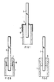
- FIG. 1 to 3 one end of a flash lamp is shown, which has a tube 1 made of translucent Al2O3, with which two electrodes are tightly connected, of which the electrode 2 is shown.
- the electrode 2 is brazed with braze 3 to a cap 4, which covers the end of the tube 1.
- the tube 1 is metallized at its end and tightly connected to the cap 4 by a hard solder 5.
- the materials for the electrode 2, the cap 4 and the solders 3 and 5 are chosen so that their thermal expansion is approximately equal to the thermal expansion of Al2O3. As a material for the electrode 2 and the cap 4 comes z. B. Niobium in question.
- the electrode 2 is hermetically connected to the tube 1 by a glass plug 6, which is fused on the one hand to the electrode 2 and on the other hand to the tube 1.
- the material of the glass plug 6 must have exactly the same thermal expansion as that of Al2O3 and the material of the electrode 2, z. B. niobium.
- the example according to FIG. 3 again has a glass plug 7 which is fused directly to the electrode 2. Between the tube 1 and the glass plug 7, however, a glass solder 8 is provided, which enables easy connection. In this example too, all four components 1, 2, 7, 8 must match in their thermal expansion.
- Niobium was mentioned as the material for the metal parts, namely the electrodes and possibly the metal caps in the example according to FIG. 1.
- suitable metal alloys can also be used which, in their thermal expansion, match Al2O3 and, if appropriate, glass.
Abstract
Die Erfindung betrifft eine Blitzlampe mit einem lichtdurchlässigen Rohr (1), in dem zwei Elektroden (2) liegen, die mit dem Rohr (1) dicht verbunden sind. Das Rohr (1) besteht aus Al2O3. Die Elektroden (2) können mit Metallkappen (4) verbunden sein, die das Rohr (1) an seinen Enden umfassen und mit einer auf dem Rohr (1) dort aufgebrachten Metallschicht verlötet sind. Es ist aber auch möglich, in die Rohrenden Glaspfropfen einzusetzen, die mit den Elektroden (2) und gegebenenfalls unter Verwendung eines Glaslotes auch mit dem Rohr (1) verschmolzen sind.
Description
- Die Erfindung betrifft eine Blitzlampe mit einem lichtdurchlässigen Rohr, in dem zwei Elektroden liegen, die mit dem Rohr dicht verbunden sind.
- Es sind Entladungs-Blitzlampen bekannt, die als Entladungsgefäß ein Rohr aus Hartglas aufweisen, das in seiner Wärmeausdehnung derjenigen der verwendeten Elektroden (Wolfram, Molybdän) angepaßt ist und eine automatische Massenfertigung ermöglicht.
- Es ist ferner bekannt, für Hochleistungs-Blitzlampen als Entladungsgefäß ein Rohr aus Quarzglas vorzusehen, das einerseits eine wesentlich höhere Belastbarkeit im Lichtbogen aufweist als Hartglas, andererseits jedoch durch seine extrem kleine Wärmeausdehnung bei der Einschmelzung der Elektroden Handarbeit erfordert.
- Der Erfindung liegt die Aufgabe zugrunde, eine Blitzlampe so auszubilden, daß sie bei hoher Belastbarkeit eine wirtschaftliche Massenfertigung erlaubt.
- Diese Aufgabe ist erfindungsgemäß dadurch gelöst, daß das Rohr aus Aluminiumoxid Al₂O₃ besteht. Al₂O₃ besitzt eine hohe Beständigkeit gegenüber dem Lichtbogen. Seine Wärmeausdehnung, die zu Niob und bestimmten Elektrodenlegierungen paßt, erlaubt eine wirtschaftliche Massenfertigung.
- Die Erfindung ist nachfolgend anhand dreier in den Figuren 1 bis 3 dargestellter Ausführungsbeispiele näher erläutert.
- In den Figuren 1 bis 3 ist jeweils das eine Ende einer Blitzlampe dargestellt, die ein Rohr 1 aus lichtdurchlässigem Al₂O₃ aufweist, mit dem zwei Elektroden dicht verbunden sind, von denen die Elektrode 2 dargestellt ist.
- Bei dem Beispiel gemäß Figur 1 ist die Elektrode 2 mit Hartlot 3 mit einer Kappe 4 verlötet, die das Ende des Rohres 1 umfaßt. Das Rohr 1 ist an seinem Ende metallisiert und mit der Kappe 4 durch ein Hartlot 5 dicht verbunden. Die Materialien für die Elektrode 2, die Kappe 4 sowie die Lote 3 und 5 sind so gewählt, daß ihre Wärmeausdehnung etwa gleich der Wärmeausdehnung von Al₂O₃ ist. Als Material für die Elektrode 2 und die Kappe 4 kommt z. B. Niob in Frage.
- Bei dem Beispiel gemäß Figur 2 ist die Elektrode 2 mit dem Rohr 1 durch einen Glaspfropfen 6 hermetisch verbunden, der einerseits mit der Elektrode 2 und andererseits mit dem Rohr 1 verschmolzen ist. Das Material des Glaspfropfens 6 muß dabei in seiner Wärmeausdehnung genau derjenigen von Al₂O₃ sowie dem Material der Elektrode 2, z. B. Niob, angepaßt sein.
- Das Beispiel gemäß Figur 3 weist wieder einen Glaspfropfen 7 auf, der direkt mit der Elektrode 2 verschmolzen ist. Zwischen dem Rohr 1 und dem Glaspfropfen 7 ist jedoch ein Glaslot 8 vorgesehen, das eine leichte Verbindung ermöglicht. Auch bei diesem Beispiel müssen alle vier Komponenten 1, 2, 7, 8 in ihrer Wärmeausdehnung übereinstimmen.
- Als Material für die Metallteile, nämlich die Elektroden und gegebenenfalls bei dem Beispiel gemäß Figur 1 die Metallkappen, wurde Niob genannt. Es sind jedoch auch geeignete Metallegierungen verwendbar, die in ihrer Wärmeausdehnung zu Al₂O₃ sowie gegebenenfalls zu Glas passen.
Claims (4)
1. Blitzlampe mit einem lichtdurchlässigen Rohr (1), in dem zwei Elektroden (2) liegen, die mit dem Rohr (1) dicht verbunden sind, dadurch gekennzeichnet, daß das Rohr (1) aus Aluminiumoxid AL₂O₃ besteht.
2. Blitzlampe nach Anspruch 1, dadurch gekennzeichnet, daß die Elektroden (2) mit Metallkappen (4) verbunden sind, die das Rohr (1) an seinen Enden umfassen und mit einer auf dem Rohr (1) dort aufgebrachten Metallschicht verlötet sind.
3. Blitzlampe nach Anspruch 1, dadurch gekennzeichnet, daß in die Rohrenden Glaspfropfen (6, 7) eingeschmolzen sind, die von den Elektroden (2) durchsetzt werden.
4. Blitzlampe nach Anspruch 3, dadurch gekennzeichnet, daß zwischen Glaspfropfen (7) und Rohr (1) ein Glaslot (8) vorgesehen ist.
Applications Claiming Priority (2)
| Application Number | Priority Date | Filing Date | Title |
|---|---|---|---|
| DE3634006 | 1986-10-06 | ||
| DE3634006 | 1986-10-06 |
Publications (1)
| Publication Number | Publication Date |
|---|---|
| EP0263379A1 true EP0263379A1 (de) | 1988-04-13 |
Family
ID=6311159
Family Applications (1)
| Application Number | Title | Priority Date | Filing Date |
|---|---|---|---|
| EP87114059A Withdrawn EP0263379A1 (de) | 1986-10-06 | 1987-09-25 | Blitzlampe |
Country Status (2)
| Country | Link |
|---|---|
| EP (1) | EP0263379A1 (de) |
| JP (1) | JPS6360265U (de) |
Cited By (3)
| Publication number | Priority date | Publication date | Assignee | Title |
|---|---|---|---|---|
| EP0392060A1 (de) * | 1989-04-14 | 1990-10-17 | Heimann Optoelectronics GmbH | Blitzlampe |
| EP0786797A3 (de) * | 1996-01-29 | 1997-11-12 | General Electric Company | Bogenröhre für Hochdruck-Entladungslampe |
| WO2001011653A1 (de) * | 1999-08-05 | 2001-02-15 | Patent-Treuhand-Gesellschaft für elektrische Glühlampen mbH | Gasentladungslampe und zugehöriges herstellungsverfahren |
Families Citing this family (1)
| Publication number | Priority date | Publication date | Assignee | Title |
|---|---|---|---|---|
| JP4548212B2 (ja) * | 2005-05-17 | 2010-09-22 | ウシオ電機株式会社 | 閃光放電ランプ |
Citations (3)
| Publication number | Priority date | Publication date | Assignee | Title |
|---|---|---|---|---|
| US4004173A (en) * | 1965-12-27 | 1977-01-18 | Sydney Alfred Richard Rigden | Niobium alumina sealing and product produced thereby |
| US4147952A (en) * | 1974-12-12 | 1979-04-03 | Gte Sylvania Incorporated | Method of sealing alumina arc tube |
| US4203050A (en) * | 1977-07-28 | 1980-05-13 | Heimann Gmbh | Gas discharge lamp and method |
-
1987
- 1987-09-25 EP EP87114059A patent/EP0263379A1/de not_active Withdrawn
- 1987-10-02 JP JP15212987U patent/JPS6360265U/ja active Pending
Patent Citations (3)
| Publication number | Priority date | Publication date | Assignee | Title |
|---|---|---|---|---|
| US4004173A (en) * | 1965-12-27 | 1977-01-18 | Sydney Alfred Richard Rigden | Niobium alumina sealing and product produced thereby |
| US4147952A (en) * | 1974-12-12 | 1979-04-03 | Gte Sylvania Incorporated | Method of sealing alumina arc tube |
| US4203050A (en) * | 1977-07-28 | 1980-05-13 | Heimann Gmbh | Gas discharge lamp and method |
Cited By (6)
| Publication number | Priority date | Publication date | Assignee | Title |
|---|---|---|---|---|
| EP0392060A1 (de) * | 1989-04-14 | 1990-10-17 | Heimann Optoelectronics GmbH | Blitzlampe |
| US5091675A (en) * | 1989-04-14 | 1992-02-25 | Heimann Gmbh | Flashbulb having hard glass containing emitter substances |
| EP0786797A3 (de) * | 1996-01-29 | 1997-11-12 | General Electric Company | Bogenröhre für Hochdruck-Entladungslampe |
| US5866982A (en) * | 1996-01-29 | 1999-02-02 | General Electric Company | Arctube for high pressure discharge lamp |
| WO2001011653A1 (de) * | 1999-08-05 | 2001-02-15 | Patent-Treuhand-Gesellschaft für elektrische Glühlampen mbH | Gasentladungslampe und zugehöriges herstellungsverfahren |
| US6605892B1 (en) | 1999-08-05 | 2003-08-12 | Patent-Treuhand-Gesellschaft Fuer Elektrische Gluehlampen Mbh | Gas discharge lamp and method for the production thereof |
Also Published As
| Publication number | Publication date |
|---|---|
| JPS6360265U (de) | 1988-04-21 |
Similar Documents
| Publication | Publication Date | Title |
|---|---|---|
| EP0652586B1 (de) | Metallhalogenidentladungslampe mit keramischem Entladungsgefäss und Herstellverfahren für eine derartige Lampe | |
| DE10291427B4 (de) | Halogen-Metalldampflampe für einen Kraftfahrzeugscheinwerfer | |
| DE3317963A1 (de) | Keramikkondensator mit schichtaufbau | |
| DE2442898A1 (de) | Mehrschichtiger monolithischer keramik-kondensator und verfahren zur justierung und einstellung desselben | |
| EP0245734B1 (de) | Elektrische Lampe | |
| EP0248977B1 (de) | Elektrisches Anzündelement und Verfahren zu seiner Herstellung | |
| DE2207009C3 (de) | Überspannungsableiter | |
| DE69731374T2 (de) | Niederdruckentladunglampe | |
| DE19649332C1 (de) | Resonator mit Kristall | |
| DE2340931C3 (de) | Verfahren zur Herstellung elektrischer Glühlampen, Entladungslampen oder -röhren | |
| DE4015463A1 (de) | Verfahren zum anbringen von leitenden anschluessen an keramikkomponenten | |
| DE3722576C2 (de) | ||
| EP0263379A1 (de) | Blitzlampe | |
| DE1923138B2 (de) | Verfahren zur herstellung einer hermetischen verbindung wenigstens zweier polykristalliner koerper aus al tief 2 o tief 3 | |
| DE2920042A1 (de) | Kurzbogenentladungslampe | |
| DE3506296A1 (de) | Gasentladungslampe | |
| EP0803898A2 (de) | Elektrode für Entladungslampen | |
| DE2737931C2 (de) | Endverschluß für eine Entladungslampe | |
| EP2188828B1 (de) | Hochdruckentladungslampe | |
| EP1730766A2 (de) | Elektrodensystem für eine hochdruckentladungslampe | |
| EP1292549B1 (de) | Materialverbund sowie herstellung und verwendung des materialverbunds | |
| DE69908227T2 (de) | Hochdruck-Entladungslampe | |
| DE2535986A1 (de) | Elektrische hochdruck-entladungsroehre | |
| DE3034595A1 (de) | Elektrische gluehlampe mit wenigstens einem waagerechten gluehkoerper | |
| EP0325157B1 (de) | Gasentladungslampe |
Legal Events
| Date | Code | Title | Description |
|---|---|---|---|
| PUAI | Public reference made under article 153(3) epc to a published international application that has entered the european phase |
Free format text: ORIGINAL CODE: 0009012 |
|
| AK | Designated contracting states |
Kind code of ref document: A1 Designated state(s): CH DE FR GB IT LI NL |
|
| 17P | Request for examination filed |
Effective date: 19880506 |
|
| STAA | Information on the status of an ep patent application or granted ep patent |
Free format text: STATUS: THE APPLICATION HAS BEEN WITHDRAWN |
|
| 18W | Application withdrawn |
Withdrawal date: 19880727 |
|
| RIN1 | Information on inventor provided before grant (corrected) |
Inventor name: DUENISCH, INGO, DIPL.-PHYS. Inventor name: ACHTER, EUGEN |