EP0263293A1 - Arc quenching device - Google Patents
Arc quenching device Download PDFInfo
- Publication number
- EP0263293A1 EP0263293A1 EP87112437A EP87112437A EP0263293A1 EP 0263293 A1 EP0263293 A1 EP 0263293A1 EP 87112437 A EP87112437 A EP 87112437A EP 87112437 A EP87112437 A EP 87112437A EP 0263293 A1 EP0263293 A1 EP 0263293A1
- Authority
- EP
- European Patent Office
- Prior art keywords
- quenching
- arc
- parallel
- plates
- wall part
- Prior art date
- Legal status (The legal status is an assumption and is not a legal conclusion. Google has not performed a legal analysis and makes no representation as to the accuracy of the status listed.)
- Granted
Links
Images
Classifications
-
- H—ELECTRICITY
- H01—ELECTRIC ELEMENTS
- H01H—ELECTRIC SWITCHES; RELAYS; SELECTORS; EMERGENCY PROTECTIVE DEVICES
- H01H9/00—Details of switching devices, not covered by groups H01H1/00 - H01H7/00
- H01H9/30—Means for extinguishing or preventing arc between current-carrying parts
- H01H9/34—Stationary parts for restricting or subdividing the arc, e.g. barrier plate
- H01H9/36—Metal parts
- H01H9/362—Mounting of plates in arc chamber
-
- H—ELECTRICITY
- H01—ELECTRIC ELEMENTS
- H01H—ELECTRIC SWITCHES; RELAYS; SELECTORS; EMERGENCY PROTECTIVE DEVICES
- H01H9/00—Details of switching devices, not covered by groups H01H1/00 - H01H7/00
- H01H9/30—Means for extinguishing or preventing arc between current-carrying parts
- H01H9/302—Means for extinguishing or preventing arc between current-carrying parts wherein arc-extinguishing gas is evolved from stationary parts
-
- H—ELECTRICITY
- H01—ELECTRIC ELEMENTS
- H01H—ELECTRIC SWITCHES; RELAYS; SELECTORS; EMERGENCY PROTECTIVE DEVICES
- H01H9/00—Details of switching devices, not covered by groups H01H1/00 - H01H7/00
- H01H9/30—Means for extinguishing or preventing arc between current-carrying parts
- H01H9/34—Stationary parts for restricting or subdividing the arc, e.g. barrier plate
- H01H9/342—Venting arrangements for arc chutes
Definitions
- This alternating arrangement of ventilation openings ensures that there is always a sufficiently large outlet cross section for exhaust air per individual arc without the stability of the end plate being impaired and without additional measures for ventilation being required.
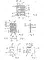
- the rear wall part 14 On one end face of the quenching plate stack 10, the rear wall part 14 is arranged, which has grooves 28 which are separated from one another by webs 30.
- the individual quenching plates 20 of the quenching plate stack 12 are inserted into the grooves 28 of the rear wall part 14 and are kept at a distance from one another by the webs 30.
- With 21 a bevel of the side edges is shown, which facilitates the handling of the extinguishing plates 20 when inserted into the grooves 28 of the rear wall part 14.
Abstract
Description
Die Erfindung betrifft eine Lichtbogenlöscheinrichtung für ein elektrisches Schaltgerät mit einer Kontaktstelle mit Kontaktstücken, zwischen denen beim Öffnen der Kontaktstelle ein Lichtbogen zündet, der über parallel angeordnete Lichtbogenleitschienen in eine Lichtbogenlöschkammer kommutiert, in der zwischen den Lichtbogenleitschienen ein auf seiner Rückseite von einem rückwärtigen Wandteil und auf seinen Längsseiten von je einem seitlichen Wandteil aus isolierendem Material umgebenes Löschblechpaket mit parallel zu den Lichtbogenleitschienen gestapelten Löschblechen angeordnet ist, welche an ihren Längskanten Haltenasen aufweisen.The invention relates to an arc extinguishing device for an electrical switching device with a contact point with contact pieces, between which an arc ignites when the contact point is opened, which commutates via arc guide rails arranged in parallel into an arc quenching chamber, in which between the arc guide rails one on its back from a rear wall part and on its longitudinal sides, each surrounded by a lateral wall part made of insulating material, are arranged with a baffle plate stack with baffle plates stacked parallel to the arc guide rails, which have retaining lugs on their longitudinal edges.
Bei der Betätigung von Schaltkontakten in elektrischen Schaltgeräten bildet sich beim Öffnen der Kontaktstelle, d. h. beim Auseinanderziehen der Kontaktstücke, ein Schaltlichtbogen, dessen Größe und Intensität mit höherer Stromstärke zunimmt. Derartige Schaltlichtbögen sollen schnell von den Kontaktstücken abkommutieren und in einer hierzu vorgesehen Löscheinrichtung gelöscht werden.When switching contacts in electrical switching devices are actuated, a switching arc is formed when the contact point is opened, ie when the contact pieces are pulled apart, the size and intensity of which increases with higher current intensity. Switching arcs of this type are intended to rapidly commutate from the contact pieces and be extinguished in a quenching device provided for this purpose.
Es sind daher seit langem Maßnahmen zur Unterdrückung bzw. zur Löschung der sogenannten Schaltlichtbögen in elektrischen Schaltgeräten bekannt.Measures to suppress or extinguish the so-called switching arcs in electrical switching devices have therefore been known for a long time.
Eine Lichtbogenlöscheinrichtung ist aus der EP-A -0 164 632 bekannt geworden, bei der ein aus übereinanderliegend angeordneten Löschblechen gebildetes Löschbleckpaket seitlich und rückwärtig, d. h. auf der der Kontaktstelle entgegengesetzten Stirnseite des Löschblechpakets, von Wandungen umhüllt ist. Hierbei sind die Seitenwandungen mittels an den Löschblechen angeformten Haltenasen, welche in hierfür vorgesehene Ausnehmungen in den Seitenwandungen greifen, fixiert, wahrend die rückwärtige Wandung im Abstand zu dem Löschblechpaket an den dieses in der Länge überragenden Seitenwandungen anschließt. Im hinteren Bereich der U-förmigen Umhüllung des Löschblechpakets sind Aussparungen oben und unten vorgesehen, die als Entlüftung für die Abluft dienen.An arc extinguishing device has become known from EP-A-0 164 632, in which an extinguishing sheet package formed from stacked quenching plates is arranged laterally and rearwards, i.e. in the form of a stack. H. on the end face of the quenching sheet stack opposite the contact point, is enveloped by walls. In this case, the side walls are fixed by means of retaining lugs molded onto the extinguishing plates, which engage in recesses provided for this purpose in the side walls, while the rear wall adjoins the side walls, which protrude in length, at a distance from the stack of extinguishing plates. In the rear area of the U-shaped envelope of the quenching plate package, cutouts are provided at the top and bottom, which serve as ventilation for the exhaust air.
Bei dieser Ausgestaltung ist die Anordnung der Löschbleche im Löschblechpaket entsprechend den Ausnehmungen in den Seitenwandungen festgelegt, in welche die Haltenasen der Löschbleche eingreifen. Ebenso ist die Ausdehnung der Löscheinrichtung in Längsrichtung durch die Länge der Seitenwandungen festgelegt, so daß der Einsatz dieser Löscheinrichtung nur in besonders dafür vorbereiteten Schaltgeräten möglich ist.In this embodiment, the arrangement of the quenching plates in the quenching plate stack is defined in accordance with the recesses in the side walls, in which the retaining lugs of the quenching plates engage. Likewise, the extent of the extinguishing device in the longitudinal direction is determined by the length of the side walls, so that the use of this extinguishing device is only possible in switchgear specially prepared for this purpose.
Die Erfindung hat daher die Aufgabe, eine Löscheinrichtung der oberbegrifflichen Art zu schaffen, die einfach und raumsparend gestaltet und im Hinblick auf vielseitige Einsatzmöglichkeiten kostengünstig herstellbar ist. Die Lösung dieser Aufgabe wird erfindungsgemäß dadurch erreicht daß, die seitlichen Wandteile als schmale Streifen ausgebildet sind und zur Halterung der Löschbleche dienen, daß das rückwartige Wandteil als ebene Platte mit parallelen Nuten und Stegen ausgebildet ist und unmittelbar an den Löschblechen anliegt und, daß die Löschbleche in die Nuten eingeführt sind, wahrend die Stege als Abstandhalter zwischen die einzelnen Löschbleche greifen. In vorteilhafter Ausgestaltung der Erfindung ist also vorgesehen, an der Rückseite des Löschbleckpakets eine ebene Platte anzuordnen, die mit parallelen Nuten versehen ist, in welche die Löschbleche eingeführt sind. Hierbei dienen die zwischen den Nuten befindlichen Stege gleichzeitig als Abstandhalter für die Löschbleche. Ferner ist vorgesehen, die seitlichen Wandteile, die zur Halterung der Löschbleche im Löschblechpaket dienen, als Streifen auszuführen, welche das Löschblechpaket nur in seinem vorderen, der Kontaktstelle zugewandten Bereich überdecken. Zur Aufnahme der seitlichen Wandteile in die Löschbleche ist an deren Längskanten jeweils eine kantenparallele Einformung vorgesehen, in welche die seitlichen Wandteile einfügbar sind. Auf diese Weise ist die Breite der kompletten Löscheinrichtung durch die Breite der Löschblech e bestimmt, da die Tiefe der kantenparallelen Einformungen so festgelegt ist, daß sie wenigstens der Dicke der seitlichen Wandteile entspricht.The object of the invention is therefore to create an extinguishing device of the generic type which is simple and space-saving and which can be produced inexpensively with regard to a wide range of possible uses. The solution to this problem is achieved in that the side wall parts are designed as narrow strips and serve to hold the quenching plates, that the rear wall part is designed as a flat plate with parallel grooves and webs and rests directly on the quenching plates and that the quenching plates are inserted into the grooves, while the webs engage as spacers between the individual fire extinguishing plates. In an advantageous embodiment of the invention, provision is therefore made for a flat plate to be arranged on the back of the blanket pack, which is provided with parallel grooves into which the sheetplates are inserted. Here, the webs located between the grooves also serve as spacers for the extinguishing plates. Furthermore, it is provided that the side wall parts, which serve to hold the fire-extinguishing plates in the fire-extinguishing plate package, are designed as strips which only cover the fire-extinguishing plate package in its front area facing the contact point. To accommodate the side wall parts in the fire-fighting plates, an edge-parallel indentation is provided on each of their longitudinal edges, into which the side wall parts can be inserted. In this way, the width of the complete extinguishing device is determined by the width of the baffle plate e, since the depth of the parallel-parallel recesses is determined so that it corresponds at least to the thickness of the side wall parts.
Mit dieser kompakten Ausgestaltung, bei der die aus den rückwärtigen und den seitlichen Wandteilen gebildete Umhüllung unmittelbar am Löschblechpaket anliegt und bereichsweise innerhalb dessen Außenkontur liegt, eröffnen sich Möglichkeiten für einen vielseitigen Einsatz in verschiedenen Schaltgeräten, ohne daß an deren Gestal tung oder an der Beschaffenheit von einzelnen Bauelementen der Löscheinrichtung Änderungen vorzunehmen wären. Eine derart kompakt gestaltete Löscheinrichtung läßt sich problemlos auch in unterschiedlich gestalteten Schaltgeräten unterbringen, sofern diese eine Löschkammer aufweisen. Eine Anpassung der Löscheinrichtung an verschiedene Einsatzerfordernisse ist ohne Änderung der Schaltgeräte bzw. deren Gehäuse nur durch Variation, z. B. der Löschblechabstände, möglich.With this compact design, in which the envelope formed from the rear and the side wall parts lies directly on the fire-extinguishing plate package and lies within its outer contour in some areas, possibilities are opened up for versatile use in various switching devices, without the need for their design tion or the nature of individual components of the extinguishing device would have to be changed. Such a compact extinguishing device can easily be accommodated in differently designed switching devices, provided that they have an extinguishing chamber. An adaptation of the extinguishing device to different application requirements is possible without changing the switching devices or their housing only by variation, for. B. the spacing of the baffle, possible.
Gemäß einer besonderen Ausgestaltung der Erfindung sind die kantenparallelen Einformungen an den Löschblechen einerseits mit einer Haltenase und andererseits mit zwei Haltenasen versehen, so daß durch Wenden des Löschbleches um seine Längsachse wahlweise die dem Betrachter zugewandte Längskante eine oder zwei Haltenasen aufweist. Die Haltenasen sind hierbei bezogen auf die Länge der kantenparallelen Einformung symmetrisch angeordnet. Dabei befindet sich die einzelne Haltenase auf halber Länge der kantenparallelen Einformung, während die paarweise vorgesehenen Haltenasen in geringem Abstand zum seitlichen Rand der kantenparllelen Einformung vorgesehen sind.According to a special embodiment of the invention, the edge-parallel indentations on the extinguishing plates are provided on the one hand with a holding lug and on the other hand with two holding lugs, so that by turning the extinguishing plate around its longitudinal axis, the longitudinal edge facing the viewer has one or two holding lugs. The retaining lugs are arranged symmetrically with respect to the length of the parallel molding. The individual retaining lug is located at half the length of the edge-parallel indentation, while the retaining lugs provided in pairs are provided at a short distance from the lateral edge of the edge-parallel indentation.
Dementsprechend sind die seitlichen Wandteile mit in Abstand zueinander in drei zur Längsseite parallelen Reihen angeordneten Ausnehmungen versehen, in welche die Haltenasen greifen. Hierbei dienen die beiden äußeren Reihen von Halteöffnungen für die Aufnahme der paarweise vorgesehenen Haltenasen, während die in der Mitte angeordneten Halteöffnungen, die horizontal versetzt zu den äußeren Halteöffnungen angeordnet sind, zur Aufnahme der einzelnen Haltenasen.Accordingly, the side wall parts are provided with spaced-apart recesses in three rows parallel to the long side, into which the retaining lugs engage. The two outer rows of holding openings serve to receive the holding lugs provided in pairs, while the holding openings arranged in the middle, which are horizontally offset from the outer holding openings, serve to hold the individual holding lugs.
Mittels dieser alternierenden Anordnung der Haltenasen bzw. der Halteöffnungen in den seitlichen Wandteilen bietet sich eine einfache Möglichkeit, die Abstände der Löschbleche und dadurch die Lichtbogenspannung der Einzellichtbögen zwischen den Löschblechen, welche zur Strombegrenzungswirkung des Schaltgeräts beiträgt, einsatzgerecht einzustellen.By means of this alternating arrangement of the holding lugs or the holding openings in the side wall parts, there is a simple possibility to adjust the spacing of the quenching plates and thereby the arc voltage of the individual arcs between the quenching plates, which contributes to the current limiting effect of the switching device.
In gleicher Weise stimmt gemäß einer weiteren Verbesserung der Erfindung der Abstand der Nuten im rückwärtigen Wandteil überein mit dem vertikalen Abstand der beiden Anordnungen von Halteöffnungen, die zur Aufnahme entweder der einzelnen oder der paarweise vorgesehenen Haltenasen an den Längskanten der Löschbleche dienen.In the same way, according to a further improvement of the invention, the spacing of the grooves in the rear wall part corresponds to the vertical spacing of the two arrangements of holding openings which serve to receive either the individual or the paired holding lugs on the longitudinal edges of the extinguishing plates.
Eine weitere Verbesserung der Erfindung zeigt sich in der Lichtbogenbeständigkeit des als Platte, z. B. aus einem Duroplast, ausgebildeten rückwärtigen Wandteils sowie in der bedarfsgerechten Ausstattung mit Entlüftungsöffnungen. Während die Nuten in der rückwärtigen Abschlußplatte durchgehend eingeformt sind, ist der Verlauf der als Abstandhalter für die Löschbleche dienenden Stege regelmäßig durch Entlüftungsöffnungen unterbrochen. Diese Entlüftungsöffnungen sind stegweise versetzt nahe dem Seitenrand in die Abschlußplatte eingelassen und haben die Form trapezförmiger, insbesondere rechtekkiger Schlitze, deren Breite der Stegbreite entspricht. Mit stegweise versetzt ist hierbei gemeint, daß die Entlüftungsöffnungen durch welche die beim Brennen des Lichtbogens entstehenden Brenngase entweichen können und die je Steg nur einfach vorgesehen sind, beim ersten Steg am linken Rand, beim zweiten Steg am rechten Rand, beim dritten Steg wieder am linken Rand usw. angeordnet sind und sich diese Anordnung über die gesamte Höhe der Abschlußplatte fortsetzt.Another improvement of the invention is the arc resistance of the plate, e.g. B. from a thermoset, trained rear wall part and in the appropriate equipment with ventilation openings. While the grooves are continuously molded in the rear end plate, the course of the webs serving as spacers for the extinguishing plates is regularly interrupted by ventilation openings. These ventilation openings are offset in the web near the side edge and have the shape of trapezoidal, in particular rectangular, slots, the width of which corresponds to the web width. Staggered here is meant that the ventilation openings through which the combustion gases generated during the burning of the arc can escape and which are only provided for each web, on the first web on the left edge, on the second web on the right edge, on the third web again on the left Edge etc. are arranged and this arrangement continues over the entire height of the end plate.
Mit dieser alternierenden Anordnung von Entlüftungsöffnungen ist sichergestellt, daß stets ein ausreichend großer Austrittsquerschnitt für Abluft je E inzellichtbogen zur Verfügung steht, ohne daß die Stabilitat der Abschlußplatte beeinträchtigt ist und ohne daß zusätzliche Maßnahmen zur Entlüftung erforderlich sind.This alternating arrangement of ventilation openings ensures that there is always a sufficiently large outlet cross section for exhaust air per individual arc without the stability of the end plate being impaired and without additional measures for ventilation being required.
Bei einer weiteren vorteilhaften Ausgestaltung der Erfindung weisen die Löschbleche auf ihrer der Kontaktstelle zugewandten Seite jeweils eine erste parabolische Ausnehmung auf, an deren Scheitelpunkt eine zweite parabolische Ausnehmung angeordnet ist. Die Tiefe der beiden Ausnehmungen, die zur Lichtbogenbeständigkeit der Löschbleche beitragen, indem die Fußpunktbildung an bevorzugten Stellen vermieden wird, beträgt additiv etwa die halbe Länge eines Löschbleches. Die Tiefe der zweiten Ausnehmung beträgt hierbei etwa 1/6 der Tiefe der ersten Ausnehmung.In a further advantageous embodiment of the invention, the quenching plates each have a first parabolic recess on their side facing the contact point, at the apex of which a second parabolic recess is arranged. The depth of the two recesses, which contribute to the arc resistance of the quenching plates by avoiding the formation of base points in preferred locations, is additively approximately half the length of a quenching plate. The depth of the second recess is approximately 1/6 of the depth of the first recess.
Diese und weitere vorteilhafte Ausgestaltungen und Verbesserungen der Erfindung sind den Unteransprüchen zu entnehmen.These and further advantageous refinements and improvements of the invention can be found in the subclaims.
Anhand der Zeichnung, in der ein Ausführungsbeispiel der Erfindung dargestellt ist, sollen die Erfindung, vorteilhafter Ausgestaltungen und Verbesserungen der Erfindung sowie weitere Vorteile näher erläutert und beschrieben werden.The invention, advantageous refinements and improvements to the invention and further advantages are to be explained and described in more detail with reference to the drawing, in which an exemplary embodiment of the invention is shown.
Es zeigen:
- Figur 1 eine Lichtbogenlöscheinrichtung in seitlicher Ansicht
- Figur 2 ein rückwärtiges Wandteil
- Figur 3 ein rückwärtiges Wandteil im Längsschnitt gemäß der Linie I-I in Figur 3
- Figur 4 einen Querschnitt durch ein rückwärtiges Wandteil gemäß der Linie II-II in Figur 3
- Figur 5 ein Löschblech in Draufsicht
- Figur 6 ein Löschblechpaket in Draufsicht
- Figure 1 is an arc extinguishing device in a side view
- Figure 2 shows a rear wall part
- 3 shows a rear wall part in longitudinal section along the line II in Figure 3
- FIG. 4 shows a cross section through a rear wall part along the line II-II in FIG. 3
- Figure 5 is a quenching plate in plan view
- Figure 6 shows a quenching plate package in plan view
Figur 1 zeigt eine Löscheinrichtung 10 mit einem Löschbleckpaket 12, einem rückwärtigen Wandteil 14 und einem seitlichen Wandteil 16. Das Löschblechpaket 12 ist aus einzelnen Löschblechen 20 gebildet, welche parallel übereinanderliegend angeordnet sind. Die in Figur 1 sichtbaren Seitenkanten 22 der Löschbleche 20 besitzen Haltenasen 24, 26, welche in Halteöffnungen 25, 27 in dem seitlichen Wandteil 16 form- und kraftschlüssig eingreifen. Wie aus Figur 1 ferner hervorgeht, sind die Halteöffnungen 25, 27 in dem seitlichen Wandteil 16 versetzt zueinander angeordnet, so daß sich in einer Ebene zwei Halteöffnungen 27 nebeneinander befinden und in der darüber liegenden Ebene nur eine einzelne Halteöffnung 25. An einer Stirnseite des Löschblechpakets 10 ist das rückwärtige Wandteil 14 angeordnet, welches Nuten 28 aufweist, die von Stegen 30 voneinander getrennt sind. Die einzelnen Löschbleche 20 des Löschblechpakets 12 sind in die Nuten 28 des rückwärtigen Wandteils 14 eingeführt und durch die Stege 30 gegeneinander auf Abstand gehalten. Mit 21 ist eine Anschrägung der Seitenkanten dargestellt, welche die Handhabung der Löschbleche 20 beim Einführen in die Nuten 28 des rückwärtigen Wandteiles 14 erleichtert.FIG. 1 shows an
In Figur 2 ist die Ansicht eines rückwärtigen Wandteils 14 dargestellt, bei dem Nuten 28 und Stege 30 miteinander abwechseln. Deutlich erkennbar sind in geringem Abstand zu den beiden seitlichen Längskanten des rückwärtigen Wandteils angeordnete rechteckige Ausnehmungen 32 zu erkennen, die sich im Bereich der Stege befinden und von Steg 30 zu Steg 30 versetzt übereinander in zwei parallelen Reihen 31 angeordnet sind. In ähnlicher Weise wie zuvor bei den seitlichen Wandteilen und den dort angeordneten Halteöffnungen 25, 27 sind auch hier die Ausnehmungen, die als Entlüftungsöffnungen 32 für die Ableitung der beim Brennen eines Lichtbogens entstehenden Abluft dienen, abwechselnd von Steg 30 zum nächsten Steg 30 mal auf der einen und dann auf der anderen Seite des rückwärtigen Wandteils 14 angeordnet. Auf diese Weise ist jeder Steg 30 mit einer Entlüftungsöffnung 32 versehen, die gegenüber der des benachbarten Steges 30 seitlich versetzt angeordnet ist. Durch diese Gestaltung und Anordnung des rückwärtigen Wandteils 14 wird erreicht, daß der Lichtbogeneinlauf gegenüber der rückwärtig offenen Anordnung nur minimal nachteilig beeinflußt wird. Ferner ist zur Verstärkung der Lichtbogenkühlung erfindungsgemäß vorgeseh en, das rückwärtige Wandteil aus gasendem Material zu fertigen, d.h. aus einem Material, welches unter der Einwirkung des Lichtbogens durch Ausgasen einen Druckaufbau in der Lichtbogenlöschkammer und eine intensive Kühlung des Lichtbogens verursacht, womit die Löschwirkung unterstützt wird.FIG. 2 shows the view of a
In Figur 3 ist ein Längsschnitt durch ein rückwärtiges Wandteil 14 gezeigt entsprechend der in Figur 2 gezeigten Schnittlinie I-I. In dieser Ansicht sind deutlich die Nuten 28 sowie die Stege 30 zu erkennen, welche von Entlüftungsöffnungen 32 durchbrochen sind. Aus dieser Darstellung wird deutlich, daß die Entlüftungsöffnungen 32 wechselweise am rückwartigen Wandteil 14 angeordnet sind.FIG. 3 shows a longitudinal section through a
In Figur 4 ist ein Querschnitt durch ein rückwärtiges Wandteil 14 gemäß Figur 2 gezeigt entsprechend dem dort angegebenen Schnittverlauf II-II. Demgemäß verläuft der Schnitt durch einen Steg 30, so daß der größte Teil der Abbildung in Figur 5 eine Schraffur aufweist. Die Entlüftungsöffnung 32 unterbricht den Verlauf des Steges 30 und gibt gleichzeitig in dieser Darstellung den Blick frei auf den benachbarten Steg 30.FIG. 4 shows a cross section through a
In Figur 5 ist ein einzelnes Löschblech 20 dargestellt, welches an seinen Längskanten 22 die bereits erwähnten Anschrägungen 21 sowie kantenparallele Einformungen 34 aufweist, in denen Haltenasen 24, 26 angeformt sind und welche zur Aufnahme der seitlichen Bandteile 16 dienen. Wie vorstehend bereits ausgeführt, ist eine kantenparallele Einformung 34 mit einer Haltenase 24 versehen, die dabei etwa auf halber Länge 36 der Einformung 34 angeordnet ist. Die gegenüberliegende kantenparallele Einformung 34 ist mit zwei Haltenasen 26 versehen, die jeweils etwa bei einviertel und bei dreiviertel der Länge der kantenparallelen Einformung 34 angeordnet sind. Während die rückwärtige Stirnkante 37 des Löschblechs 20 geradlinig verläuft und in die Nuten 28 des rückwärtigen Wandteils 14 eingeführt wird, ist die der Kontaktstelle zugewandte vordere Stirnkante 35 des Löschblechs 20 mit einer parabolisch geformten Ausnehmung 38 versehen, deren Tiefe etwa die halbe Länge eines Löschbleches 20 beträgt und an deren Scheitelpunkt eine weitere, allerdings kleinere ebenfalls parabolische Ausnehmung 39 angeordnet ist. Die Tiefe der zweiten Ausnehmung 39 beträgt etwa 1/6 der Tiefe der ersten Ausnehmung 38.FIG. 5 shows a single fire-extinguishing
In Figur 6 ist die Draufsicht auf eine Löscheinrichtung gemäß der Erfindung dargestellt, bei der sowohl die in die kantenparallelen Ausnehmungen 34 eingefügten seitlichen Wandteile 16 zu erkennen sind mit dem diese durchdringenden Haltenasen 24, 26 als auch das an der Rückseite des Löschblechpakets 12 angeornete rückwärtige Wandteil 14. Ebenso sind die frontseitigen Ausnehmungen 38 und 39 zu sehen, welche dem in der Kontaktstelle entstehenden Lichtbogen zugewandt sind.FIG. 6 shows the top view of an extinguishing device according to the invention, in which both the
Die erfinderische Ausgestaltung der Löscheinrichtung 10 gestattet es auf einfache und kostengünstige Weise, die Anordnung der Löschbleche 20 zueinander, d. h. sowohl ihren Abstand als auch ihre Dicke, den jeweiligen anwendungsbezogenen Erfordernissen einsatzgerecht anzupassen, da lediglich das aus Löschblechen 20, den seitlichen Haltestreifen 16 sowie den rückwärtigen Wandteil 14 gebildete Löschblechpaket 12 eventuellen Änderungen unterliegt. Hierbei kann zunächst, wie bereits erläutert, der Abstand der Löschbleche und damit die jeweilige Spannung der Einzellichtbögen durch Weglassen jedes zweiten Löschbleches verändert werden.The inventive design of the extinguishing
Andererseits bedeutet es keinen nennenswerten Aufwand, die seitlichen Wandteile 16, aber auch die rückwärtigen Wandteile 14, mit unterschiedlichen Abstandmarken herzustellen und zu bevorraten, ggf. abgestimmt auf geringere Löschblechdicken. Ein derartiger Aufwand ist vernachlässigbar im Vergleich dazu, wenn Änderungen an der Gehäusegestaltung des Schaltgerätes erforderlich würden. On the other hand, it means no noteworthy effort to manufacture and stock the
Claims (12)
Applications Claiming Priority (2)
| Application Number | Priority Date | Filing Date | Title |
|---|---|---|---|
| DE3630447 | 1986-09-06 | ||
| DE19863630447 DE3630447A1 (en) | 1986-09-06 | 1986-09-06 | ARC EXTINGUISHING DEVICE |
Publications (2)
| Publication Number | Publication Date |
|---|---|
| EP0263293A1 true EP0263293A1 (en) | 1988-04-13 |
| EP0263293B1 EP0263293B1 (en) | 1992-03-11 |
Family
ID=6309089
Family Applications (1)
| Application Number | Title | Priority Date | Filing Date |
|---|---|---|---|
| EP87112437A Expired - Lifetime EP0263293B1 (en) | 1986-09-06 | 1987-08-27 | Arc quenching device |
Country Status (2)
| Country | Link |
|---|---|
| EP (1) | EP0263293B1 (en) |
| DE (2) | DE3630447A1 (en) |
Cited By (6)
| Publication number | Priority date | Publication date | Assignee | Title |
|---|---|---|---|---|
| WO1994017539A1 (en) * | 1993-01-27 | 1994-08-04 | Felten & Guilleaume Austria Ag | Extinguishing stack for an arc extinguishing chamber |
| DE19757332C1 (en) * | 1997-12-22 | 1999-07-22 | Siemens Ag | Arc quenching device for a switching device |
| FR2873511A1 (en) * | 2004-07-21 | 2006-01-27 | Soule Prot Surtensions Sa | DEVICE FOR PROTECTION AGAINST OVERVOLTAGES, OVERLOADS OR SHORT CIRCUITS WITH IMPROVED CUT-OFF POWER |
| EP1622179A1 (en) * | 2004-07-27 | 2006-02-01 | Siemens Aktiengesellschaft | Arc extinguishing device and low voltage circuit breaker with an arc extinguishing device |
| WO2006065129A1 (en) * | 2004-10-26 | 2006-06-22 | Eaton Electric N.V. | Arcing chamber for safety switch |
| EP3846192A1 (en) | 2019-12-30 | 2021-07-07 | Schneider Electric USA, Inc. | Arc chute for circuit protective devices |
Families Citing this family (13)
| Publication number | Priority date | Publication date | Assignee | Title |
|---|---|---|---|---|
| DE19518051A1 (en) * | 1995-05-17 | 1996-11-21 | Abb Patent Gmbh | Arc extinguishing device esp. for small modular switch devices e.g. circuit breakers |
| DE19518049A1 (en) * | 1995-05-17 | 1996-11-21 | Abb Patent Gmbh | Arc extinguishing device esp. for small modular switch device e.g. circuit breaker |
| KR19980054146U (en) * | 1996-12-31 | 1998-10-07 | 박병재 | Rear lamp coupling structure of automobile |
| FR2802701B1 (en) * | 1999-12-20 | 2002-01-18 | Schneider Electric Ind Sa | SWITCHING DEVICE FOR A SWITCHING APPARATUS |
| DE10312820B4 (en) * | 2003-03-22 | 2012-04-19 | Abb Ag | Arc quenching plate assembly for an electrical switch, in particular an electrical circuit breaker |
| DE102008021138A1 (en) | 2007-04-28 | 2008-10-30 | Abb Ag | Electric arc extinguishing plate arrangement for use in e.g. circuit breaker, has electric arc extinguishing plates held by rib at distance to each other, where rib is projected from box broad side to box interior |
| DE102009056190B3 (en) * | 2009-11-27 | 2011-05-12 | Abb Ag | Arc quenching device and switching device |
| DE102009056480B4 (en) | 2009-12-01 | 2011-12-08 | Abb Ag | Installation switching device with an arc quenching device |
| EP2393093B1 (en) | 2010-06-01 | 2015-09-16 | ABB Technology AG | Arc chute, circuit breaker for a medium voltage circuit, and use of a polymer plate |
| DE102010032715A1 (en) | 2010-07-29 | 2012-02-02 | Abb Ag | Arc extinguishing device for electric switch mounting device, has plate sections produced by insulation materials arranged between inlet supporting feet to cover inlet supporting feet and longitudinal side edges |
| DE102010034264B3 (en) * | 2010-08-13 | 2012-02-23 | Abb Ag | Electrical installation switching device has exhaust air duct that extends in longitudinal direction parallel to end wall of extinguishing chamber, to which exhaust air streams of extinguishing gases are passed via flow guiding elements |
| DE102010053507B4 (en) | 2010-12-04 | 2012-07-05 | Abb Ag | Installation switching device with an arc quenching device |
| CN105900204B (en) * | 2014-06-12 | 2018-06-01 | 西门子公司 | For the arc extinguishing chamber device of electromagnetic switchgear |
Citations (4)
| Publication number | Priority date | Publication date | Assignee | Title |
|---|---|---|---|---|
| DE7020036U (en) * | 1970-05-29 | 1970-08-13 | Bbc Brown Boveri & Cie | INSTALLATION SELF-SWITCH WITH BLOW-PLATE SPARK CHAMBER. |
| DE2217031A1 (en) * | 1972-04-08 | 1973-10-18 | Licentia Gmbh | ARC CHAMBER |
| GB2061619A (en) * | 1979-09-14 | 1981-05-13 | Matsushita Electric Works Ltd | Circuit breaker with an arc suppressor |
| EP0164632A2 (en) * | 1984-06-13 | 1985-12-18 | Asea Brown Boveri Aktiengesellschaft | Arc extinguishing device |
-
1986
- 1986-09-06 DE DE19863630447 patent/DE3630447A1/en not_active Withdrawn
-
1987
- 1987-08-27 DE DE87112437T patent/DE3777312D1/de not_active Expired - Lifetime
- 1987-08-27 EP EP87112437A patent/EP0263293B1/en not_active Expired - Lifetime
Patent Citations (4)
| Publication number | Priority date | Publication date | Assignee | Title |
|---|---|---|---|---|
| DE7020036U (en) * | 1970-05-29 | 1970-08-13 | Bbc Brown Boveri & Cie | INSTALLATION SELF-SWITCH WITH BLOW-PLATE SPARK CHAMBER. |
| DE2217031A1 (en) * | 1972-04-08 | 1973-10-18 | Licentia Gmbh | ARC CHAMBER |
| GB2061619A (en) * | 1979-09-14 | 1981-05-13 | Matsushita Electric Works Ltd | Circuit breaker with an arc suppressor |
| EP0164632A2 (en) * | 1984-06-13 | 1985-12-18 | Asea Brown Boveri Aktiengesellschaft | Arc extinguishing device |
Cited By (10)
| Publication number | Priority date | Publication date | Assignee | Title |
|---|---|---|---|---|
| WO1994017539A1 (en) * | 1993-01-27 | 1994-08-04 | Felten & Guilleaume Austria Ag | Extinguishing stack for an arc extinguishing chamber |
| AU674719B2 (en) * | 1993-01-27 | 1997-01-09 | Felten & Guilleaume Austria Ag | Extinguishing stack for an arc extinguishing chamber |
| DE19757332C1 (en) * | 1997-12-22 | 1999-07-22 | Siemens Ag | Arc quenching device for a switching device |
| US6288354B1 (en) | 1997-12-22 | 2001-09-11 | Siemens Aktiengesellschaft | Switching device with an arc extinguishing device |
| FR2873511A1 (en) * | 2004-07-21 | 2006-01-27 | Soule Prot Surtensions Sa | DEVICE FOR PROTECTION AGAINST OVERVOLTAGES, OVERLOADS OR SHORT CIRCUITS WITH IMPROVED CUT-OFF POWER |
| WO2006018513A2 (en) * | 2004-07-21 | 2006-02-23 | Abb France | Electric arc extinction device in particular for an overload protection device |
| WO2006018513A3 (en) * | 2004-07-21 | 2006-04-20 | Soule Protection Surtensions | Electric arc extinction device in particular for an overload protection device |
| EP1622179A1 (en) * | 2004-07-27 | 2006-02-01 | Siemens Aktiengesellschaft | Arc extinguishing device and low voltage circuit breaker with an arc extinguishing device |
| WO2006065129A1 (en) * | 2004-10-26 | 2006-06-22 | Eaton Electric N.V. | Arcing chamber for safety switch |
| EP3846192A1 (en) | 2019-12-30 | 2021-07-07 | Schneider Electric USA, Inc. | Arc chute for circuit protective devices |
Also Published As
| Publication number | Publication date |
|---|---|
| DE3630447A1 (en) | 1988-03-10 |
| EP0263293B1 (en) | 1992-03-11 |
| DE3777312D1 (en) | 1992-04-16 |
Similar Documents
| Publication | Publication Date | Title |
|---|---|---|
| EP0263293A1 (en) | Arc quenching device | |
| DE4410108C2 (en) | Arc quenching chamber with three barriers for the passage of arc gases | |
| DE1788098B1 (en) | Multipole circuit breaker | |
| DE19814411C1 (en) | Electromagnetic switching device with quenching chamber, esp. a high power breaker | |
| EP0309386A1 (en) | Multi-pole low-voltage circuit breaker with an insulating case and an arc quencher | |
| DE3413555C2 (en) | ||
| DE3337562A1 (en) | Extinguishing device for a line-protection circuit breaker | |
| EP0138174A2 (en) | Quenching device for an automatic circuit breaker | |
| DE3149750C2 (en) | ||
| DE3908102A1 (en) | Automatic circuit breaker, especially a line protective circuit breaker | |
| DE19735522C1 (en) | Bracket for extinguishing sheets of an arc extinguishing device | |
| EP0051756B1 (en) | Arc extinguishing device, in particular for an automatic cut out | |
| EP0183145B1 (en) | Electrical switch device, especially a protective power circuit breaker | |
| DE1005153B (en) | Arc extinguishing device for electrical switches | |
| DE2923234A1 (en) | FOR LOW VOLTAGE SWITCHGEARS OF CIRCUIT BREAKERS OR CIRCUIT BREAKERS | |
| EP1017072A2 (en) | Electric commutation device, in particular a circuit breaker | |
| DE3243079A1 (en) | Switchgear cabinet | |
| EP0382325B1 (en) | Arc control device with arc interruption plates | |
| DE1126010B (en) | Loeschblechordnung for low voltage switchgear | |
| DE19643643B4 (en) | Circuit breaker with arc extinguishing chamber and deionization | |
| EP0387761A2 (en) | Automatic circuit breaker, particularly automatic cut-out | |
| EP0028013A1 (en) | Power circuit breaker provided with a casing | |
| EP0681737B1 (en) | Extinguishing stack for an arc extinguishing chamber | |
| DE1175318B (en) | Arc extinguishing device | |
| DE8531354U1 (en) | Arc chamber |
Legal Events
| Date | Code | Title | Description |
|---|---|---|---|
| PUAI | Public reference made under article 153(3) epc to a published international application that has entered the european phase |
Free format text: ORIGINAL CODE: 0009012 |
|
| AK | Designated contracting states |
Kind code of ref document: A1 Designated state(s): DE GB IT |
|
| 17P | Request for examination filed |
Effective date: 19880513 |
|
| RAP1 | Party data changed (applicant data changed or rights of an application transferred) |
Owner name: ASEA BROWN BOVERI AKTIENGESELLSCHAFT |
|
| 17Q | First examination report despatched |
Effective date: 19910314 |
|
| GRAA | (expected) grant |
Free format text: ORIGINAL CODE: 0009210 |
|
| AK | Designated contracting states |
Kind code of ref document: B1 Designated state(s): DE GB IT |
|
| ITF | It: translation for a ep patent filed |
Owner name: DE DOMINICIS & MAYER S.R.L. |
|
| REF | Corresponds to: |
Ref document number: 3777312 Country of ref document: DE Date of ref document: 19920416 |
|
| GBT | Gb: translation of ep patent filed (gb section 77(6)(a)/1977) | ||
| PLBE | No opposition filed within time limit |
Free format text: ORIGINAL CODE: 0009261 |
|
| STAA | Information on the status of an ep patent application or granted ep patent |
Free format text: STATUS: NO OPPOSITION FILED WITHIN TIME LIMIT |
|
| 26N | No opposition filed | ||
| PGFP | Annual fee paid to national office [announced via postgrant information from national office to epo] |
Ref country code: GB Payment date: 20010628 Year of fee payment: 15 |
|
| REG | Reference to a national code |
Ref country code: GB Ref legal event code: IF02 |
|
| PG25 | Lapsed in a contracting state [announced via postgrant information from national office to epo] |
Ref country code: GB Free format text: LAPSE BECAUSE OF NON-PAYMENT OF DUE FEES Effective date: 20020827 |
|
| GBPC | Gb: european patent ceased through non-payment of renewal fee |
Effective date: 20020827 |
|
| PG25 | Lapsed in a contracting state [announced via postgrant information from national office to epo] |
Ref country code: IT Free format text: LAPSE BECAUSE OF NON-PAYMENT OF DUE FEES Effective date: 20050827 |
|
| PGFP | Annual fee paid to national office [announced via postgrant information from national office to epo] |
Ref country code: DE Payment date: 20060816 Year of fee payment: 20 |