EP0262894A2 - Verfahren zur Erzeugung von Kohlendioxyd und Wasserstoff - Google Patents
Verfahren zur Erzeugung von Kohlendioxyd und Wasserstoff Download PDFInfo
- Publication number
- EP0262894A2 EP0262894A2 EP87308554A EP87308554A EP0262894A2 EP 0262894 A2 EP0262894 A2 EP 0262894A2 EP 87308554 A EP87308554 A EP 87308554A EP 87308554 A EP87308554 A EP 87308554A EP 0262894 A2 EP0262894 A2 EP 0262894A2
- Authority
- EP
- European Patent Office
- Prior art keywords
- carbon dioxide
- hydrogen
- combustor
- gas
- stream
- Prior art date
- Legal status (The legal status is an assumption and is not a legal conclusion. Google has not performed a legal analysis and makes no representation as to the accuracy of the status listed.)
- Granted
Links
- CURLTUGMZLYLDI-UHFFFAOYSA-N Carbon dioxide Chemical compound O=C=O CURLTUGMZLYLDI-UHFFFAOYSA-N 0.000 title claims abstract description 170
- 229910002092 carbon dioxide Inorganic materials 0.000 title claims abstract description 85
- 239000001569 carbon dioxide Substances 0.000 title claims abstract description 77
- 229910052739 hydrogen Inorganic materials 0.000 title claims abstract description 58
- 239000001257 hydrogen Substances 0.000 title claims abstract description 58
- UFHFLCQGNIYNRP-UHFFFAOYSA-N Hydrogen Chemical compound [H][H] UFHFLCQGNIYNRP-UHFFFAOYSA-N 0.000 title claims abstract description 45
- 238000004519 manufacturing process Methods 0.000 title claims abstract description 11
- VNWKTOKETHGBQD-UHFFFAOYSA-N methane Chemical compound C VNWKTOKETHGBQD-UHFFFAOYSA-N 0.000 claims abstract description 92
- 239000007789 gas Substances 0.000 claims abstract description 56
- 238000002485 combustion reaction Methods 0.000 claims abstract description 42
- 238000010926 purge Methods 0.000 claims abstract description 32
- XLYOFNOQVPJJNP-UHFFFAOYSA-N water Substances O XLYOFNOQVPJJNP-UHFFFAOYSA-N 0.000 claims abstract description 31
- QVGXLLKOCUKJST-UHFFFAOYSA-N atomic oxygen Chemical compound [O] QVGXLLKOCUKJST-UHFFFAOYSA-N 0.000 claims abstract description 28
- 229910052760 oxygen Inorganic materials 0.000 claims abstract description 28
- 239000001301 oxygen Substances 0.000 claims abstract description 28
- 238000000034 method Methods 0.000 claims abstract description 22
- 238000001179 sorption measurement Methods 0.000 claims abstract description 13
- 150000002431 hydrogen Chemical class 0.000 claims description 14
- 239000000203 mixture Substances 0.000 claims description 14
- 239000003463 adsorbent Substances 0.000 claims description 9
- QGZKDVFQNNGYKY-UHFFFAOYSA-N Ammonia Chemical compound N QGZKDVFQNNGYKY-UHFFFAOYSA-N 0.000 claims description 6
- VUZPPFZMUPKLLV-UHFFFAOYSA-N methane;hydrate Chemical compound C.O VUZPPFZMUPKLLV-UHFFFAOYSA-N 0.000 claims description 6
- 229930195733 hydrocarbon Natural products 0.000 claims description 5
- 150000002430 hydrocarbons Chemical class 0.000 claims description 5
- 239000004215 Carbon black (E152) Substances 0.000 claims description 4
- 238000004064 recycling Methods 0.000 claims description 4
- 238000005057 refrigeration Methods 0.000 claims description 4
- 229910021529 ammonia Inorganic materials 0.000 claims description 3
- 238000010521 absorption reaction Methods 0.000 claims 1
- 239000000470 constituent Substances 0.000 claims 1
- 239000007788 liquid Substances 0.000 abstract description 12
- 230000005611 electricity Effects 0.000 abstract description 4
- 239000012535 impurity Substances 0.000 abstract 1
- 230000008929 regeneration Effects 0.000 abstract 1
- 238000011069 regeneration method Methods 0.000 abstract 1
- 229960004424 carbon dioxide Drugs 0.000 description 60
- UGFAIRIUMAVXCW-UHFFFAOYSA-N Carbon monoxide Chemical compound [O+]#[C-] UGFAIRIUMAVXCW-UHFFFAOYSA-N 0.000 description 13
- 229910002091 carbon monoxide Inorganic materials 0.000 description 12
- 229940105305 carbon monoxide Drugs 0.000 description 12
- 239000000047 product Substances 0.000 description 11
- XKRFYHLGVUSROY-UHFFFAOYSA-N Argon Chemical compound [Ar] XKRFYHLGVUSROY-UHFFFAOYSA-N 0.000 description 6
- 239000006227 byproduct Substances 0.000 description 5
- PXHVJJICTQNCMI-UHFFFAOYSA-N nickel Substances [Ni] PXHVJJICTQNCMI-UHFFFAOYSA-N 0.000 description 5
- 239000003054 catalyst Substances 0.000 description 4
- 238000006243 chemical reaction Methods 0.000 description 4
- 239000007795 chemical reaction product Substances 0.000 description 4
- 238000010586 diagram Methods 0.000 description 4
- 239000000446 fuel Substances 0.000 description 4
- 229910052786 argon Inorganic materials 0.000 description 3
- 239000003345 natural gas Substances 0.000 description 3
- 238000002407 reforming Methods 0.000 description 3
- XLOMVQKBTHCTTD-UHFFFAOYSA-N Zinc monoxide Chemical compound [Zn]=O XLOMVQKBTHCTTD-UHFFFAOYSA-N 0.000 description 2
- 238000000746 purification Methods 0.000 description 2
- 239000002918 waste heat Substances 0.000 description 2
- OKTJSMMVPCPJKN-UHFFFAOYSA-N Carbon Chemical compound [C] OKTJSMMVPCPJKN-UHFFFAOYSA-N 0.000 description 1
- RYGMFSIKBFXOCR-UHFFFAOYSA-N Copper Chemical compound [Cu] RYGMFSIKBFXOCR-UHFFFAOYSA-N 0.000 description 1
- 239000005751 Copper oxide Substances 0.000 description 1
- 208000036366 Sensation of pressure Diseases 0.000 description 1
- 229910052799 carbon Inorganic materials 0.000 description 1
- 238000001311 chemical methods and process Methods 0.000 description 1
- 239000000567 combustion gas Substances 0.000 description 1
- 230000006835 compression Effects 0.000 description 1
- 238000007906 compression Methods 0.000 description 1
- 238000001816 cooling Methods 0.000 description 1
- 229910000431 copper oxide Inorganic materials 0.000 description 1
- 239000003546 flue gas Substances 0.000 description 1
- 238000005984 hydrogenation reaction Methods 0.000 description 1
- 230000010354 integration Effects 0.000 description 1
- 238000012986 modification Methods 0.000 description 1
- 230000004048 modification Effects 0.000 description 1
- 229910052759 nickel Inorganic materials 0.000 description 1
- 239000003921 oil Substances 0.000 description 1
- 239000011368 organic material Substances 0.000 description 1
- 239000003208 petroleum Substances 0.000 description 1
- 238000010248 power generation Methods 0.000 description 1
- 238000002203 pretreatment Methods 0.000 description 1
- 239000011541 reaction mixture Substances 0.000 description 1
- 238000011084 recovery Methods 0.000 description 1
- 238000000629 steam reforming Methods 0.000 description 1
- 239000000126 substance Substances 0.000 description 1
- 239000011787 zinc oxide Substances 0.000 description 1
Images
Classifications
-
- F—MECHANICAL ENGINEERING; LIGHTING; HEATING; WEAPONS; BLASTING
- F25—REFRIGERATION OR COOLING; COMBINED HEATING AND REFRIGERATION SYSTEMS; HEAT PUMP SYSTEMS; MANUFACTURE OR STORAGE OF ICE; LIQUEFACTION SOLIDIFICATION OF GASES
- F25J—LIQUEFACTION, SOLIDIFICATION OR SEPARATION OF GASES OR GASEOUS OR LIQUEFIED GASEOUS MIXTURES BY PRESSURE AND COLD TREATMENT OR BY BRINGING THEM INTO THE SUPERCRITICAL STATE
- F25J3/00—Processes or apparatus for separating the constituents of gaseous or liquefied gaseous mixtures involving the use of liquefaction or solidification
- F25J3/02—Processes or apparatus for separating the constituents of gaseous or liquefied gaseous mixtures involving the use of liquefaction or solidification by rectification, i.e. by continuous interchange of heat and material between a vapour stream and a liquid stream
- F25J3/04—Processes or apparatus for separating the constituents of gaseous or liquefied gaseous mixtures involving the use of liquefaction or solidification by rectification, i.e. by continuous interchange of heat and material between a vapour stream and a liquid stream for air
- F25J3/04642—Recovering noble gases from air
- F25J3/04648—Recovering noble gases from air argon
-
- C—CHEMISTRY; METALLURGY
- C01—INORGANIC CHEMISTRY
- C01B—NON-METALLIC ELEMENTS; COMPOUNDS THEREOF; METALLOIDS OR COMPOUNDS THEREOF NOT COVERED BY SUBCLASS C01C
- C01B3/00—Hydrogen; Gaseous mixtures containing hydrogen; Separation of hydrogen from mixtures containing it; Purification of hydrogen
- C01B3/50—Separation of hydrogen or hydrogen containing gases from gaseous mixtures, e.g. purification
- C01B3/56—Separation of hydrogen or hydrogen containing gases from gaseous mixtures, e.g. purification by contacting with solids; Regeneration of used solids
-
- C—CHEMISTRY; METALLURGY
- C01—INORGANIC CHEMISTRY
- C01B—NON-METALLIC ELEMENTS; COMPOUNDS THEREOF; METALLOIDS OR COMPOUNDS THEREOF NOT COVERED BY SUBCLASS C01C
- C01B32/00—Carbon; Compounds thereof
- C01B32/50—Carbon dioxide
-
- F—MECHANICAL ENGINEERING; LIGHTING; HEATING; WEAPONS; BLASTING
- F25—REFRIGERATION OR COOLING; COMBINED HEATING AND REFRIGERATION SYSTEMS; HEAT PUMP SYSTEMS; MANUFACTURE OR STORAGE OF ICE; LIQUEFACTION SOLIDIFICATION OF GASES
- F25J—LIQUEFACTION, SOLIDIFICATION OR SEPARATION OF GASES OR GASEOUS OR LIQUEFIED GASEOUS MIXTURES BY PRESSURE AND COLD TREATMENT OR BY BRINGING THEM INTO THE SUPERCRITICAL STATE
- F25J1/00—Processes or apparatus for liquefying or solidifying gases or gaseous mixtures
- F25J1/0002—Processes or apparatus for liquefying or solidifying gases or gaseous mixtures characterised by the fluid to be liquefied
- F25J1/0005—Light or noble gases
- F25J1/001—Hydrogen
-
- F—MECHANICAL ENGINEERING; LIGHTING; HEATING; WEAPONS; BLASTING
- F25—REFRIGERATION OR COOLING; COMBINED HEATING AND REFRIGERATION SYSTEMS; HEAT PUMP SYSTEMS; MANUFACTURE OR STORAGE OF ICE; LIQUEFACTION SOLIDIFICATION OF GASES
- F25J—LIQUEFACTION, SOLIDIFICATION OR SEPARATION OF GASES OR GASEOUS OR LIQUEFIED GASEOUS MIXTURES BY PRESSURE AND COLD TREATMENT OR BY BRINGING THEM INTO THE SUPERCRITICAL STATE
- F25J1/00—Processes or apparatus for liquefying or solidifying gases or gaseous mixtures
- F25J1/0002—Processes or apparatus for liquefying or solidifying gases or gaseous mixtures characterised by the fluid to be liquefied
- F25J1/0027—Oxides of carbon, e.g. CO2
-
- F—MECHANICAL ENGINEERING; LIGHTING; HEATING; WEAPONS; BLASTING
- F25—REFRIGERATION OR COOLING; COMBINED HEATING AND REFRIGERATION SYSTEMS; HEAT PUMP SYSTEMS; MANUFACTURE OR STORAGE OF ICE; LIQUEFACTION SOLIDIFICATION OF GASES
- F25J—LIQUEFACTION, SOLIDIFICATION OR SEPARATION OF GASES OR GASEOUS OR LIQUEFIED GASEOUS MIXTURES BY PRESSURE AND COLD TREATMENT OR BY BRINGING THEM INTO THE SUPERCRITICAL STATE
- F25J1/00—Processes or apparatus for liquefying or solidifying gases or gaseous mixtures
- F25J1/02—Processes or apparatus for liquefying or solidifying gases or gaseous mixtures requiring the use of refrigeration, e.g. of helium or hydrogen ; Details and kind of the refrigeration system used; Integration with other units or processes; Controlling aspects of the process
- F25J1/0228—Coupling of the liquefaction unit to other units or processes, so-called integrated processes
- F25J1/0234—Integration with a cryogenic air separation unit
-
- F—MECHANICAL ENGINEERING; LIGHTING; HEATING; WEAPONS; BLASTING
- F25—REFRIGERATION OR COOLING; COMBINED HEATING AND REFRIGERATION SYSTEMS; HEAT PUMP SYSTEMS; MANUFACTURE OR STORAGE OF ICE; LIQUEFACTION SOLIDIFICATION OF GASES
- F25J—LIQUEFACTION, SOLIDIFICATION OR SEPARATION OF GASES OR GASEOUS OR LIQUEFIED GASEOUS MIXTURES BY PRESSURE AND COLD TREATMENT OR BY BRINGING THEM INTO THE SUPERCRITICAL STATE
- F25J1/00—Processes or apparatus for liquefying or solidifying gases or gaseous mixtures
- F25J1/02—Processes or apparatus for liquefying or solidifying gases or gaseous mixtures requiring the use of refrigeration, e.g. of helium or hydrogen ; Details and kind of the refrigeration system used; Integration with other units or processes; Controlling aspects of the process
- F25J1/0243—Start-up or control of the process; Details of the apparatus used; Details of the refrigerant compression system used
- F25J1/0279—Compression of refrigerant or internal recycle fluid, e.g. kind of compressor, accumulator, suction drum etc.
- F25J1/0281—Compression of refrigerant or internal recycle fluid, e.g. kind of compressor, accumulator, suction drum etc. characterised by the type of prime driver, e.g. hot gas expander
- F25J1/0284—Electrical motor as the prime mechanical driver
-
- F—MECHANICAL ENGINEERING; LIGHTING; HEATING; WEAPONS; BLASTING
- F25—REFRIGERATION OR COOLING; COMBINED HEATING AND REFRIGERATION SYSTEMS; HEAT PUMP SYSTEMS; MANUFACTURE OR STORAGE OF ICE; LIQUEFACTION SOLIDIFICATION OF GASES
- F25J—LIQUEFACTION, SOLIDIFICATION OR SEPARATION OF GASES OR GASEOUS OR LIQUEFIED GASEOUS MIXTURES BY PRESSURE AND COLD TREATMENT OR BY BRINGING THEM INTO THE SUPERCRITICAL STATE
- F25J3/00—Processes or apparatus for separating the constituents of gaseous or liquefied gaseous mixtures involving the use of liquefaction or solidification
- F25J3/02—Processes or apparatus for separating the constituents of gaseous or liquefied gaseous mixtures involving the use of liquefaction or solidification by rectification, i.e. by continuous interchange of heat and material between a vapour stream and a liquid stream
- F25J3/04—Processes or apparatus for separating the constituents of gaseous or liquefied gaseous mixtures involving the use of liquefaction or solidification by rectification, i.e. by continuous interchange of heat and material between a vapour stream and a liquid stream for air
- F25J3/04521—Coupling of the air fractionation unit to an air gas-consuming unit, so-called integrated processes
- F25J3/04527—Integration with an oxygen consuming unit, e.g. glass facility, waste incineration or oxygen based processes in general
- F25J3/04533—Integration with an oxygen consuming unit, e.g. glass facility, waste incineration or oxygen based processes in general for the direct combustion of fuels in a power plant, so-called "oxyfuel combustion"
-
- C—CHEMISTRY; METALLURGY
- C01—INORGANIC CHEMISTRY
- C01B—NON-METALLIC ELEMENTS; COMPOUNDS THEREOF; METALLOIDS OR COMPOUNDS THEREOF NOT COVERED BY SUBCLASS C01C
- C01B2203/00—Integrated processes for the production of hydrogen or synthesis gas
- C01B2203/04—Integrated processes for the production of hydrogen or synthesis gas containing a purification step for the hydrogen or the synthesis gas
- C01B2203/042—Purification by adsorption on solids
-
- C—CHEMISTRY; METALLURGY
- C01—INORGANIC CHEMISTRY
- C01B—NON-METALLIC ELEMENTS; COMPOUNDS THEREOF; METALLOIDS OR COMPOUNDS THEREOF NOT COVERED BY SUBCLASS C01C
- C01B2203/00—Integrated processes for the production of hydrogen or synthesis gas
- C01B2203/04—Integrated processes for the production of hydrogen or synthesis gas containing a purification step for the hydrogen or the synthesis gas
- C01B2203/0465—Composition of the impurity
- C01B2203/0475—Composition of the impurity the impurity being carbon dioxide
-
- C—CHEMISTRY; METALLURGY
- C01—INORGANIC CHEMISTRY
- C01B—NON-METALLIC ELEMENTS; COMPOUNDS THEREOF; METALLOIDS OR COMPOUNDS THEREOF NOT COVERED BY SUBCLASS C01C
- C01B2203/00—Integrated processes for the production of hydrogen or synthesis gas
- C01B2203/04—Integrated processes for the production of hydrogen or synthesis gas containing a purification step for the hydrogen or the synthesis gas
- C01B2203/0465—Composition of the impurity
- C01B2203/048—Composition of the impurity the impurity being an organic compound
-
- C—CHEMISTRY; METALLURGY
- C01—INORGANIC CHEMISTRY
- C01B—NON-METALLIC ELEMENTS; COMPOUNDS THEREOF; METALLOIDS OR COMPOUNDS THEREOF NOT COVERED BY SUBCLASS C01C
- C01B2203/00—Integrated processes for the production of hydrogen or synthesis gas
- C01B2203/04—Integrated processes for the production of hydrogen or synthesis gas containing a purification step for the hydrogen or the synthesis gas
- C01B2203/0465—Composition of the impurity
- C01B2203/0495—Composition of the impurity the impurity being water
-
- F—MECHANICAL ENGINEERING; LIGHTING; HEATING; WEAPONS; BLASTING
- F25—REFRIGERATION OR COOLING; COMBINED HEATING AND REFRIGERATION SYSTEMS; HEAT PUMP SYSTEMS; MANUFACTURE OR STORAGE OF ICE; LIQUEFACTION SOLIDIFICATION OF GASES
- F25J—LIQUEFACTION, SOLIDIFICATION OR SEPARATION OF GASES OR GASEOUS OR LIQUEFIED GASEOUS MIXTURES BY PRESSURE AND COLD TREATMENT OR BY BRINGING THEM INTO THE SUPERCRITICAL STATE
- F25J2230/00—Processes or apparatus involving steps for increasing the pressure of gaseous process streams
- F25J2230/22—Compressor driver arrangement, e.g. power supply by motor, gas or steam turbine
-
- Y—GENERAL TAGGING OF NEW TECHNOLOGICAL DEVELOPMENTS; GENERAL TAGGING OF CROSS-SECTIONAL TECHNOLOGIES SPANNING OVER SEVERAL SECTIONS OF THE IPC; TECHNICAL SUBJECTS COVERED BY FORMER USPC CROSS-REFERENCE ART COLLECTIONS [XRACs] AND DIGESTS
- Y02—TECHNOLOGIES OR APPLICATIONS FOR MITIGATION OR ADAPTATION AGAINST CLIMATE CHANGE
- Y02C—CAPTURE, STORAGE, SEQUESTRATION OR DISPOSAL OF GREENHOUSE GASES [GHG]
- Y02C20/00—Capture or disposal of greenhouse gases
- Y02C20/40—Capture or disposal of greenhouse gases of CO2
-
- Y—GENERAL TAGGING OF NEW TECHNOLOGICAL DEVELOPMENTS; GENERAL TAGGING OF CROSS-SECTIONAL TECHNOLOGIES SPANNING OVER SEVERAL SECTIONS OF THE IPC; TECHNICAL SUBJECTS COVERED BY FORMER USPC CROSS-REFERENCE ART COLLECTIONS [XRACs] AND DIGESTS
- Y02—TECHNOLOGIES OR APPLICATIONS FOR MITIGATION OR ADAPTATION AGAINST CLIMATE CHANGE
- Y02P—CLIMATE CHANGE MITIGATION TECHNOLOGIES IN THE PRODUCTION OR PROCESSING OF GOODS
- Y02P20/00—Technologies relating to chemical industry
- Y02P20/10—Process efficiency
- Y02P20/129—Energy recovery, e.g. by cogeneration, H2recovery or pressure recovery turbines
-
- Y—GENERAL TAGGING OF NEW TECHNOLOGICAL DEVELOPMENTS; GENERAL TAGGING OF CROSS-SECTIONAL TECHNOLOGIES SPANNING OVER SEVERAL SECTIONS OF THE IPC; TECHNICAL SUBJECTS COVERED BY FORMER USPC CROSS-REFERENCE ART COLLECTIONS [XRACs] AND DIGESTS
- Y02—TECHNOLOGIES OR APPLICATIONS FOR MITIGATION OR ADAPTATION AGAINST CLIMATE CHANGE
- Y02P—CLIMATE CHANGE MITIGATION TECHNOLOGIES IN THE PRODUCTION OR PROCESSING OF GOODS
- Y02P20/00—Technologies relating to chemical industry
- Y02P20/151—Reduction of greenhouse gas [GHG] emissions, e.g. CO2
Definitions
- This invention relates to the co-production of enriched streams of separate carbon dioxide and hydrogen products from for example the effluent of a methane steam reformer.
- a pressure swing adsorption (PSA) unit is employed to separate the effluent from a methane steam reformer into a primary stream of enriched hydrogen.
- the purge gas from the H2 PSA unit is combusted to yield carbon dioxide and to produce valuable energy in the form of electricity which can be employed to liquify a portion of the enriched hydrogen stream and carbon dioxide combustion product.
- Methane steam reformers are widely used in the petroleum and chemical process industries. Methane and water react to produce hydrogen and carbon monoxide by a well known chemical reaction.
- the hydrogen rich effluent from the methane steam reformer may be used for various purposes, for example, the reforming of hydrocarbons, the upgrading of oils and fuels, hydrogenation in the manufacture of specialty chemicals, or the production of ammonia.
- the hydrogen rich effluent of the methane steam reformer can be used to increase the hydrogen to carbon ratio of organic materials.
- the effluent from the methane steam reformer comprising carbon monoxide and hydrogen is reacted in a water-gas shift reactor with further steam to convert typically 80-95% of the carbon monoxide to carbon dioxide and hydrogen by a well known chemical reaction.
- a methane steam reformer is frequently used in association with a water-gas shift reactor and henceforth the term "methane steam reformer" will be used to encompass both the reforming and water-gas shift units.
- the effluent from a methane steam reformer is sent to a PSA unit where the carbon dioxide, carbon monoxide, methane and a portion of the hydrogen are separated out to produce a hydrogen rich primary product.
- the PSA purge gas is then combusted with oxygen or oxygen enriched gas to form a mixture of carbon dioxide and water. Water is condensed prior to supplying the carbon dioxide stream to a carbon dioxide plant. Little or no additional pre-treatment or purification is required.
- the carbon dioxide stream is an economical and advantageous source of carbon dioxide for commercial production of industrial or food grade liquid carbon dioxide.
- the hydrogen PSA purge to support combustion in the presence of pure or enriched oxygen are combusted in an internal combustion engine, gas turbine or other combustion device (herein generally referred to as the combustor) that can be used to drive an electrical power generation device.
- the exhaust gas from the combustor is typically cooled, condensing the water vapor which is subsequently removed, and preferably a portion of the exhaust gas is recycled as feed to the combustor.
- the amount of gas that is recycled controls the maximum temperature achieved in the combustor and allows the use of standard combustor hardware that is designed to operate with methane and air feed.
- combustion equipment used in the present invention can cogenerate electricity, steam, and/or mechanical energy.
- the electrical power generated by the present process could be used by the operator on site or can be sold to other parties. Co-production of electricity significantly reduces the manufacturing cost of liquid carbon dioxide.
- the electrical power obtained from the combustion of the PSA vent gas can be used to liquify, in addition to carbon dioxide, the hydrogen primary product.
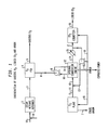
- a feed stream 1a is introduced into a methane steam reformer 2.
- the term "methane steam reformer” is herein used to encompass both reforming and water-gas shift units, although they are conventionally separate units.
- the feed stream 1a is typically a natural gas or a methane based feed, although heavier feeds such as LPG and naptha are also suitable.
- the feed stream 1a Prior to entering the methane steam reformer 2, the feed stream 1a is compressed and then mixed with pressurized steam 1b.
- the feed stream is suitably compressed to approximately 450 psig or typically 300-600 psig.
- the steam is suitably at a pressure of 1500 psig.
- the mixed feed is then passed through tubes in the reformer containing a Ni based catalyst.
- a one or two-step water gas shift reaction follows, thereby reducing the carbon monoxide concentration to below 2-3%. If one step, a high-temperature shift reactor is utilized. If two step, a high-temperature reactor is followed by a low-temperature shift reactor comprising a fixed bed of copper and zinc oxide catalyst.
- PSA unit 4 comprises adsorbers which are regenerated isothermally using a controlled sequence of depressurization and purging steps as is well known in the art.
- the PSA unit 4 may contain three to twelve adsorbers, the number depending on the size of the plant and yield required.
- the hydrogen rich stream 5 can obtain a purity of up to 99.999 volume percent hydrogen.
- the hydrogen is initially produced at about 300 psia, and typically 200 to 400 psig.
- the PSA purge gas stream 6, which is vented at low pressure (for example, under 5 psig) is a mixture of carbon dioxide, hydrogen, methane, carbon dioxide and traces of water. This stream is then compressed in a compressor 8 to about 50 to 60 psig.
- the compressed gas stream 9 is then sent to the fuel intake of an internal combustion engine 12. Entering the air intake of the internal combustion engine 12 is an admixture 10 of high oxygen concentration stream 11 and recycle stream 13, which is a recycled portion of the internal combustion engine exhaust gas and consists primarily of carbon dioxide.
- the ratio of the flow rates of streams 10 and 9 is controlled, with respect to stoichiometric, such that a slightly oxygen rich mixture is fed to the internal combustion engine.
- the ratio of the flow rates of streams 11 and 13 is controlled such that the peak temperature achieved by the engine is equal to or less than the peak temperature achieved when combusting a near stoichiometric ratio of methane and air for which the engine was designed.
- the internal combustion engine 12 is typically a four cycle, spark ignition type engine with associated electrical generator and switch gear/transformer. Power is generated as indicated by line 16 in Fig. 1. Part of this power may be consumed by the feed compressor and recycle compressor and part is consumed by the oxygen and carbon dioxide plants, as indicated by dotted lines 18, and 19. There is a net production of power which is available for export.
- cooling stream 14 includes replacing the heat exchanger with a waste heat boiler in order to produce steam.
- This steam may be used to provide energy to an ammonia adsorption refrigeration unit which in turn could be used to provide refrigeration for the liquid carbon dioxide plant.
- Other options for effective use of the internal combustion engine exhaust heat would be evident to those skilled in the art.
- the cooled gas stream is partially split into streams 17 and recycle stream 13.
- the amount of gas that comprises recycle stream 13, as mentioned previously, is selected such that the peak temperature in the internal combustion engine 12 is about the same as the peak temperature achieved when combusting the methane and air mixture for which these commercially available engines are designed.
- the stream 13 is fed to a compressor to increase the pressure such that it can be mixed with the oxygen rich stream 11.
- the resulting stream 10 as indicated above, is sent to the air intake of the internal combustion engine 12.
- the remaining portion of the cooled carbon dioxide stream is then sent to carbon dioxide liquefaction facilities to produce liquid carbon dioxide stream 18.
- an on-site oxygen plant is used to supply oxygen enriched stream 11 then a crude argon stream 7, requiring further purification, is co-produced as a valuable by-product.
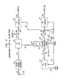
- FIG. 2 An alternative embodiment is shown in FIG. 2.
- a feed stream 20 is introduced into methane steam reformer 21. Prior to entering the methane steam reformer 21, the feed stream 20 is compressed and then mixed with pressurized steam entering via line 22.
- the feed stream is suitably compressed to approximately 450 psig or typically 300-600 psig.
- the steam is suitable at a pressure of 1500 psig.
- the mixed feed is then passed through tubes in the reformer containing a Ni based catalyst.
- PSA unit 24 comprises adsorbers which are regenerated isothermally using a controlled sequence of depressurization and purging steps as is well known in the art.
- the PSA unit 24 may contain three to twelve adsorbers, the number depending on the size of the plant.
- the hydrogen rich stream 25 can obtain a purity of up to 99.999 volume percent hydrogen.
- the hydrogen is initially produced at 300 psig and typically from 200 to 400 psig. This hydrogen is split into streams 25a and 25b.
- Stream 25a is gaseous and intended for conventional use as a primary product of the methane steam reformer.
- Stream 25b is excess capacity enriched hydrogen, which is subsequently liquified, as further explained below.
- the PSA purge gas stream 26 which is vented at low pressure (for example, under 5 psig) is a mixture of carbon dioxide, hydrogen, methane, carbon dioxide and traces of water. This stream is compressed in a compressor 28 to about 50 to 65 psig to yield a compressed gas stream 29 prior to entering an internal combustion engine 32. Entering the air intake of the internal combustion engine is an admixture 34 of a high oxygen concentration stream 30, and recycle stream 35, which is a recycled portion of the internal combustion engine exhaust gas and consists primarily of carbon dioxide. The ratio of the flow rates of streams 29 and 34 is controlled, with respect to stoichiometric, such that a slightly oxygen rich mixture is fed to the internal combustion engine.
- the ratio of the flow rates of streams 30 and 35 is controlled such that the peak temperature achieved by the engine is equal to or less than the peak temperature achieved when combusting the near stoichiometric ratio of methane and air for which the engine was designed.
- the recycle stream 35 is passed through a compressor 36 to increase the pressure such that it can be mixed with oxygen rich stream 30.
- the internal combustion engine 32 is typically a four cycle, spark ignition type engine with associated electrical generator and switch gear/transformer. Power is generated as indicated by line 33 in Fig. 2. Part of this power may be consumed during feed compression and part is consumed by the oxygen and carbon dioxide plants, respectively as indicated by dotted lines 39 and 40 respectively. A portion of the power is utilized via line 41 to provide refrigeration for liquefier 42 of the hydrogen PSA product stream 25b, thereby yielding liquid hydrogen stream 43. A small portion of the power may be sup- plied to recycle compressor 36.
- the exhaust gas stream 44 from the internal combustion engine 32 which is primarily carbon dioxide and water vapor, is cooled in heat exchanger 45 to about 100°F to condense out a substantial amount of the water combustion by-product. Waste heat recovery is optionally applicable for steam generation.
- the cooled exhaust gas stream is split into recycle stream 35, as indicated above, and non-recycle stream 46, which is sent to carbon dioxide liquefaction facilities 47 to produce liquid carbon dioxide stream 48.
- a feed stream of commercially available natural gas consisting of 9105 parts of methane at a pressure of 450 psig is introduced into a methane steam reformer.
- a stream of 18210 parts steam is also introduced into the methane steam reformer at a pressure of 1500 psig.
- the mixed feed is passed through the tubes of the reformer which contain conventional nickel catalyst to yield an effluent mixture comprising 1841 parts methane, 5722 parts carbon dioxide, 15441 parts carbon mon- oxide, 204493 parts hydrogen, and 42 parts water.
- This effluent mixture which is at a temperature of 100°F and a pressure of 300 psig, is then passed to a pressure swing adsorption system which produces as a primary product 15370 parts hydrogen at a temperature of 100°F and a pressure of 275 psig.
- a pressure swing adsorption unit Periodically the pressure swing adsorption unit is purged to obtain a purge gas comprising 1841 parts methane, 5722 parts carbon dioxide, 1541 parts carbon monoxide, 5123 parts hydrogen, and 42 parts water at a temperature of 70°F and a relatively low pressure of 5 psig.
- this purge gas Prior to introducing the purge gas into a internal combustion engine this purge gas is compressed to 50 psig.
- Also introduced into the internal com- bustion engine is 7014 parts oxygen and 12931 parts of exhaust gas recycle.
- the oxygen is produced by an on-site oxygen plant which also produces a valuable side product of 300 parts crude argon.
- the combustion reaction which takes place converts the methane, carbon monoxide and hydrogen in the purge gas to carbon dioxide and water, thereby yielding 22036 parts carbon dioxide and 8805 parts water at an elevated temperature of 950°F and a relatively low pressure of about 2 psig.
- This carbon dioxide enriched combustion gas is then passed through a heat exchanger to reduce the temperature thereof to 100°F and condense out all but 569 parts of water.
- the cooled stream is then split, with 12931 parts CO2 recycled to the intake of the internal combustion engine and 9105 parts CO2 is then introduced into a conventional carbon dioxide plant where it is compressed, dried and condensed to liquid carbon dioxide for use as industrial or food grade carbon dioxide.
- the carbon dioxide liquifier can typically have a 10% loss during liquification while producing 8194 parts of carbon dioxide.
- the liquifier is a commercially available cryogenic unit which can utilize the power produced by the internal combustion engine.
- the internal combustion engine is used to provide 6.42 megawatts of generated power which is consumed as follows:
- Table I The parameters of the process streams are shown in Table I below, in which the stream numbers correspond to the process streams shown in the diagram in FIG. 1.
- a feed stream of natural gas consisting of 9105 parts of methane is introduced into a steam reformer at a pressure of 450 psig. Also introduced into the methane steam reformer is 18210 parts steam at a temperature of 100°F and a pressure of 1500 psig. This mixed feed is passed through the tubes of the reformer containing conventional nickel based catalyst.
- the reaction product comprises 1841 parts methane, 5722 parts of carbon dioxide, 1541 parts carbon monoxide, 20493 parts hydrogen, 42 parts water at a pressure of 300 psig.
- This reaction mixture is introduced into a pressure swing adsorption system to yield 15370 parts of high purity gaseous hydrogen at a pressure of 275 psig.
- this hydrogen product is introduced into a hydrogen liquifier. Periodically the pressure swing adsorption system is purged to yield a purge gas comprising 1841 parts methane, 5722 parts carbon dioxide, 1541 parts carbon monoxide, 5123 parts hydrogen, and 42 parts water at a relatively low pressure of 5 psig. This purge gas is compressed to 50 psig before introducing the same into an internal combustion engine. Also introduced into the internal combustion engine is a mixture of an enriched oxygen stream and a recycled exhaust stream comprising 7014 parts oxygen and 12931 parts of CO2.
- the exhaust gas stream from the internal combustion engine comprises 22036 parts of carbon dioxide and 8805 parts of water at an elevated temperature of 950°F and at a pressure of 2 psig.
- the water vapor is condensed out in a heat exchange to yield a product stream of 22036 parts CO2 and 569 parts water at a temperature of 100°F and 1 psig.
- This water depleted carbon dioxide stream is then split, with 12931 parts CO2 recycled to the intake of the internal combustion engine and 9105 parts CO2 liquified in a carbon dioxide liquifier to yield 8194 parts of liquid carbon dioxide.
- the internal combustion engine is used to provide 6.42 megawatts of generated power which is consumed in the following manner:
Landscapes
- Engineering & Computer Science (AREA)
- Chemical & Material Sciences (AREA)
- Mechanical Engineering (AREA)
- Thermal Sciences (AREA)
- General Engineering & Computer Science (AREA)
- Physics & Mathematics (AREA)
- Organic Chemistry (AREA)
- Chemical Kinetics & Catalysis (AREA)
- Inorganic Chemistry (AREA)
- Combustion & Propulsion (AREA)
- Hydrogen, Water And Hydrids (AREA)
- Separation Of Gases By Adsorption (AREA)
- Carbon And Carbon Compounds (AREA)
Applications Claiming Priority (2)
| Application Number | Priority Date | Filing Date | Title |
|---|---|---|---|
| US91409886A | 1986-10-01 | 1986-10-01 | |
| US914098 | 1986-10-01 |
Publications (3)
| Publication Number | Publication Date |
|---|---|
| EP0262894A2 true EP0262894A2 (de) | 1988-04-06 |
| EP0262894A3 EP0262894A3 (en) | 1988-08-31 |
| EP0262894B1 EP0262894B1 (de) | 1992-03-18 |
Family
ID=25433913
Family Applications (1)
| Application Number | Title | Priority Date | Filing Date |
|---|---|---|---|
| EP87308554A Expired - Lifetime EP0262894B1 (de) | 1986-10-01 | 1987-09-28 | Verfahren zur Erzeugung von Kohlendioxyd und Wasserstoff |
Country Status (7)
| Country | Link |
|---|---|
| EP (1) | EP0262894B1 (de) |
| JP (1) | JPS6389402A (de) |
| AU (1) | AU576452B2 (de) |
| CA (1) | CA1326343C (de) |
| DE (1) | DE3777516D1 (de) |
| ES (1) | ES2031907T3 (de) |
| ZA (1) | ZA876418B (de) |
Cited By (10)
| Publication number | Priority date | Publication date | Assignee | Title |
|---|---|---|---|---|
| EP0341879A1 (de) * | 1988-05-04 | 1989-11-15 | The Boc Group, Inc. | Simultanerzeugung von Wasserstoff und Kohlendioxid |
| US5000925A (en) * | 1988-05-04 | 1991-03-19 | The Boc Group, Inc. | Hydrogen and carbon dioxide coproduction apparatus |
| EP0551876A2 (de) * | 1992-01-17 | 1993-07-21 | The Kansai Electric Power Co., Inc. | Verfahren zur Entfernung von Kohlendioxid aus Verbrennungsabgasen |
| EP2141119A1 (de) * | 2007-03-29 | 2010-01-06 | Nippon Oil Corporation | Verfahren zur erzeugung von wasserstoff und rückgewinnung von kohlendioxid und vorrichtung dafür |
| EP1816103A3 (de) * | 2006-02-01 | 2010-08-04 | Air Products and Chemicals, Inc. | Verfahren zur Behandlung einer Gasmischung die Wasserstoff und Kohlendioxid enthält |
| EP2407229A1 (de) | 2010-07-13 | 2012-01-18 | Air Products And Chemicals, Inc. | Verfahren zur Behandlung eines Gasgemisches mit Wasserstoff, Kohlendioxid und Schwefelwasserstoff |
| CN102822087A (zh) * | 2010-03-30 | 2012-12-12 | 乔治洛德方法研究和开发液化空气有限公司 | 减少二氧化碳排放的制备氢气的方法 |
| US20130298570A1 (en) * | 2010-11-22 | 2013-11-14 | Nigel Lawerence Dickens | Method for producing liquid hydrogen and electricity |
| CN108439337A (zh) * | 2018-03-16 | 2018-08-24 | 新地能源工程技术有限公司 | 一种天然气转化制氢的方法 |
| WO2021216742A1 (en) * | 2020-04-22 | 2021-10-28 | L'air Liquide, Societe Anonyme Pour L'etude Et L'exploitation Des Procedes Georges Claude | Nitrogen process for production of ammonia and liquid hydrogen |
Families Citing this family (5)
| Publication number | Priority date | Publication date | Assignee | Title |
|---|---|---|---|---|
| JP4839114B2 (ja) * | 2006-03-27 | 2011-12-21 | 石油コンビナート高度統合運営技術研究組合 | 液化炭酸ガス精製装置 |
| DE102009043499A1 (de) | 2009-09-30 | 2011-03-31 | Uhde Gmbh | Verfahren zum Betrieb eines IGCC-Kraftwerkprozesses mit integrierter CO2-Abtrennung |
| JP5389753B2 (ja) * | 2010-07-27 | 2014-01-15 | 株式会社日立製作所 | 石炭ガス化ガスのco2分離回収装置 |
| CN103861444B (zh) * | 2014-03-21 | 2015-10-28 | 大连理工大学 | 一种基于水合物法的二氧化碳捕集和海水淡化联产装置及方法 |
| US20240109774A1 (en) * | 2022-09-30 | 2024-04-04 | Chevron Phillips Chemical Company Lp | Multiple furnace carbon capture through fuel gas separation and hydrogen combustion product electrolysis |
Citations (2)
| Publication number | Priority date | Publication date | Assignee | Title |
|---|---|---|---|---|
| DE2930523A1 (de) * | 1979-07-27 | 1981-02-12 | Linde Ag | Verfahren und vorrichtung zur gleichzeitigen gewinnung von stickstoff und kohlendioxid |
| EP0195200A2 (de) * | 1985-03-20 | 1986-09-24 | Uhde GmbH | Verfahren zur Aufbereitung eines Restgases aus einer Niederdruckmethanolsynthese |
Family Cites Families (3)
| Publication number | Priority date | Publication date | Assignee | Title |
|---|---|---|---|---|
| US4333744A (en) * | 1981-03-09 | 1982-06-08 | Union Carbide Corporation | Two-feed pressure swing adsorption process |
| GB8513997D0 (en) * | 1985-06-04 | 1985-07-10 | Ici Plc | Technical hydrogen |
| EP0183358B1 (de) * | 1984-10-18 | 1988-12-21 | Imperial Chemical Industries Plc | Produktion von Ammoniaksynthesegas |
-
1987
- 1987-08-27 ZA ZA876418A patent/ZA876418B/xx unknown
- 1987-09-11 CA CA000546667A patent/CA1326343C/en not_active Expired - Fee Related
- 1987-09-28 DE DE8787308554T patent/DE3777516D1/de not_active Expired - Lifetime
- 1987-09-28 EP EP87308554A patent/EP0262894B1/de not_active Expired - Lifetime
- 1987-09-28 ES ES198787308554T patent/ES2031907T3/es not_active Expired - Lifetime
- 1987-09-30 AU AU79215/87A patent/AU576452B2/en not_active Ceased
- 1987-10-01 JP JP62249075A patent/JPS6389402A/ja active Granted
Patent Citations (2)
| Publication number | Priority date | Publication date | Assignee | Title |
|---|---|---|---|---|
| DE2930523A1 (de) * | 1979-07-27 | 1981-02-12 | Linde Ag | Verfahren und vorrichtung zur gleichzeitigen gewinnung von stickstoff und kohlendioxid |
| EP0195200A2 (de) * | 1985-03-20 | 1986-09-24 | Uhde GmbH | Verfahren zur Aufbereitung eines Restgases aus einer Niederdruckmethanolsynthese |
Cited By (18)
| Publication number | Priority date | Publication date | Assignee | Title |
|---|---|---|---|---|
| US4963339A (en) * | 1988-05-04 | 1990-10-16 | The Boc Group, Inc. | Hydrogen and carbon dioxide coproduction |
| US5000925A (en) * | 1988-05-04 | 1991-03-19 | The Boc Group, Inc. | Hydrogen and carbon dioxide coproduction apparatus |
| EP0341879A1 (de) * | 1988-05-04 | 1989-11-15 | The Boc Group, Inc. | Simultanerzeugung von Wasserstoff und Kohlendioxid |
| EP0551876A2 (de) * | 1992-01-17 | 1993-07-21 | The Kansai Electric Power Co., Inc. | Verfahren zur Entfernung von Kohlendioxid aus Verbrennungsabgasen |
| EP0551876A3 (en) * | 1992-01-17 | 1993-10-20 | Kansai Electric Power Co | Process for removing carbon dioxide from combustion exhaust gas |
| US5344627A (en) * | 1992-01-17 | 1994-09-06 | The Kansai Electric Power Co., Inc. | Process for removing carbon dioxide from combustion exhaust gas |
| US7909898B2 (en) | 2006-02-01 | 2011-03-22 | Air Products And Chemicals, Inc. | Method of treating a gaseous mixture comprising hydrogen and carbon dioxide |
| CN101016490B (zh) * | 2006-02-01 | 2011-06-08 | 气体产品与化学公司 | 一种处理包含氢及二氧化碳的气体混合物的方法 |
| EP1816103A3 (de) * | 2006-02-01 | 2010-08-04 | Air Products and Chemicals, Inc. | Verfahren zur Behandlung einer Gasmischung die Wasserstoff und Kohlendioxid enthält |
| EP2141119A4 (de) * | 2007-03-29 | 2011-01-05 | Nippon Oil Corp | Verfahren zur erzeugung von wasserstoff und rückgewinnung von kohlendioxid und vorrichtung dafür |
| EP2141119A1 (de) * | 2007-03-29 | 2010-01-06 | Nippon Oil Corporation | Verfahren zur erzeugung von wasserstoff und rückgewinnung von kohlendioxid und vorrichtung dafür |
| US8460630B2 (en) | 2007-03-29 | 2013-06-11 | Nippon Oil Corporation | Method and apparatus for producing hydrogen and recovering carbon dioxide |
| CN102822087A (zh) * | 2010-03-30 | 2012-12-12 | 乔治洛德方法研究和开发液化空气有限公司 | 减少二氧化碳排放的制备氢气的方法 |
| EP2407229A1 (de) | 2010-07-13 | 2012-01-18 | Air Products And Chemicals, Inc. | Verfahren zur Behandlung eines Gasgemisches mit Wasserstoff, Kohlendioxid und Schwefelwasserstoff |
| US20130298570A1 (en) * | 2010-11-22 | 2013-11-14 | Nigel Lawerence Dickens | Method for producing liquid hydrogen and electricity |
| CN108439337A (zh) * | 2018-03-16 | 2018-08-24 | 新地能源工程技术有限公司 | 一种天然气转化制氢的方法 |
| WO2021216742A1 (en) * | 2020-04-22 | 2021-10-28 | L'air Liquide, Societe Anonyme Pour L'etude Et L'exploitation Des Procedes Georges Claude | Nitrogen process for production of ammonia and liquid hydrogen |
| US11834333B2 (en) | 2020-04-22 | 2023-12-05 | L'Air Liquide, Société Anonyme pour l'Etude et l'Exploitation Procédés Georges Claude | Nitrogen process for production of ammonia and liquid hydrogen |
Also Published As
| Publication number | Publication date |
|---|---|
| AU7921587A (en) | 1988-04-14 |
| ES2031907T3 (es) | 1993-01-01 |
| AU576452B2 (en) | 1988-08-25 |
| ZA876418B (en) | 1988-03-17 |
| DE3777516D1 (de) | 1992-04-23 |
| JPS6389402A (ja) | 1988-04-20 |
| JPH0524847B2 (de) | 1993-04-09 |
| EP0262894B1 (de) | 1992-03-18 |
| EP0262894A3 (en) | 1988-08-31 |
| CA1326343C (en) | 1994-01-25 |
Similar Documents
| Publication | Publication Date | Title |
|---|---|---|
| EP0262894B1 (de) | Verfahren zur Erzeugung von Kohlendioxyd und Wasserstoff | |
| US4733528A (en) | Energy recovery | |
| US7634915B2 (en) | Systems and methods for power generation and hydrogen production with carbon dioxide isolation | |
| US5666800A (en) | Gasification combined cycle power generation process with heat-integrated chemical production | |
| CA2357527C (en) | Methanol recycle stream | |
| JP3670229B2 (ja) | 液化co2回収を伴う水素製造方法及び装置 | |
| EP0093502A1 (de) | Verfahren zur Herstellung von Ammoniak | |
| US7718159B2 (en) | Process for co-production of electricity and hydrogen-rich gas steam reforming of a hydrocarbon fraction with input of calories by combustion with hydrogen in situ | |
| WO2010018550A1 (en) | Novel steam reformer based hydrogen plant scheme for enhanced carbon dioxide recovery | |
| US6534551B2 (en) | Process and apparatus for the production of synthesis gas | |
| CA2551219A1 (en) | Systems and methods for power generation with carbon dioxide isolation | |
| CA1175655A (en) | Combined cycle apparatus for synthesis gas production | |
| US20030119919A1 (en) | Process and apparatus for the production of synthesis gas | |
| CA2283070C (en) | Integrated direct reduction iron system | |
| RU2648914C2 (ru) | Способ получения водорода и генерирования энергии | |
| GB2457970A (en) | Energy conversion process for sequestration of carbon dioxide | |
| CA1259495A (en) | Energy recovery | |
| EP0204478A2 (de) | Herstellung von technischem Wasserstoff | |
| JPH10273301A (ja) | 水素製造装置 | |
| AU2021286875B2 (en) | Method for the production of hydrogen | |
| EA006723B1 (ru) | Получение олефинов | |
| EP4178936A1 (de) | Verfahren und system zur umwandlung von nichtmethankohlenwasserstoffen zur rückgewinnung von wasserstoffgas und/oder methangas daraus | |
| JPH11111320A (ja) | 内部燃焼型改質器を使用する燃料電池発電における炭酸ガス、窒素ガス及びアルゴンガスの回収、固定方法 | |
| US20240092638A1 (en) | Oxyfuel combustion in method of recovering a hydrogen-enriched product and co2 in a hydrogen production unit | |
| EP4122876A1 (de) | Verfahren zur erhöhung der effizienz und verminderung der emissionen in einer dampfreformierungsanlage |
Legal Events
| Date | Code | Title | Description |
|---|---|---|---|
| PUAI | Public reference made under article 153(3) epc to a published international application that has entered the european phase |
Free format text: ORIGINAL CODE: 0009012 |
|
| AK | Designated contracting states |
Kind code of ref document: A2 Designated state(s): DE ES FR GB NL |
|
| PUAL | Search report despatched |
Free format text: ORIGINAL CODE: 0009013 |
|
| AK | Designated contracting states |
Kind code of ref document: A3 Designated state(s): DE ES FR GB NL |
|
| 17P | Request for examination filed |
Effective date: 19890228 |
|
| 17Q | First examination report despatched |
Effective date: 19900209 |
|
| GRAA | (expected) grant |
Free format text: ORIGINAL CODE: 0009210 |
|
| AK | Designated contracting states |
Kind code of ref document: B1 Designated state(s): DE ES FR GB NL |
|
| ET | Fr: translation filed | ||
| REF | Corresponds to: |
Ref document number: 3777516 Country of ref document: DE Date of ref document: 19920423 |
|
| REG | Reference to a national code |
Ref country code: ES Ref legal event code: FG2A Ref document number: 2031907 Country of ref document: ES Kind code of ref document: T3 |
|
| PLBE | No opposition filed within time limit |
Free format text: ORIGINAL CODE: 0009261 |
|
| STAA | Information on the status of an ep patent application or granted ep patent |
Free format text: STATUS: NO OPPOSITION FILED WITHIN TIME LIMIT |
|
| 26N | No opposition filed | ||
| REG | Reference to a national code |
Ref country code: GB Ref legal event code: IF02 |
|
| PGFP | Annual fee paid to national office [announced via postgrant information from national office to epo] |
Ref country code: NL Payment date: 20020830 Year of fee payment: 16 Ref country code: FR Payment date: 20020830 Year of fee payment: 16 |
|
| PGFP | Annual fee paid to national office [announced via postgrant information from national office to epo] |
Ref country code: GB Payment date: 20020927 Year of fee payment: 16 |
|
| PGFP | Annual fee paid to national office [announced via postgrant information from national office to epo] |
Ref country code: DE Payment date: 20020930 Year of fee payment: 16 |
|
| PGFP | Annual fee paid to national office [announced via postgrant information from national office to epo] |
Ref country code: ES Payment date: 20021009 Year of fee payment: 16 |
|
| PG25 | Lapsed in a contracting state [announced via postgrant information from national office to epo] |
Ref country code: GB Free format text: LAPSE BECAUSE OF NON-PAYMENT OF DUE FEES Effective date: 20030928 |
|
| PG25 | Lapsed in a contracting state [announced via postgrant information from national office to epo] |
Ref country code: ES Free format text: LAPSE BECAUSE OF NON-PAYMENT OF DUE FEES Effective date: 20030929 |
|
| PG25 | Lapsed in a contracting state [announced via postgrant information from national office to epo] |
Ref country code: NL Free format text: LAPSE BECAUSE OF NON-PAYMENT OF DUE FEES Effective date: 20040401 Ref country code: DE Free format text: LAPSE BECAUSE OF NON-PAYMENT OF DUE FEES Effective date: 20040401 |
|
| GBPC | Gb: european patent ceased through non-payment of renewal fee |
Effective date: 20030928 |
|
| PG25 | Lapsed in a contracting state [announced via postgrant information from national office to epo] |
Ref country code: FR Free format text: LAPSE BECAUSE OF NON-PAYMENT OF DUE FEES Effective date: 20040528 |
|
| NLV4 | Nl: lapsed or anulled due to non-payment of the annual fee |
Effective date: 20040401 |
|
| REG | Reference to a national code |
Ref country code: FR Ref legal event code: ST |
|
| REG | Reference to a national code |
Ref country code: ES Ref legal event code: FD2A Effective date: 20030929 |