EP0262240B2 - Culasse composée pour moteur à combustion interne - Google Patents
Culasse composée pour moteur à combustion interne Download PDFInfo
- Publication number
- EP0262240B2 EP0262240B2 EP86113450A EP86113450A EP0262240B2 EP 0262240 B2 EP0262240 B2 EP 0262240B2 EP 86113450 A EP86113450 A EP 86113450A EP 86113450 A EP86113450 A EP 86113450A EP 0262240 B2 EP0262240 B2 EP 0262240B2
- Authority
- EP
- European Patent Office
- Prior art keywords
- bottom wall
- wall part
- cylinder head
- reinforcement
- ribs
- Prior art date
- Legal status (The legal status is an assumption and is not a legal conclusion. Google has not performed a legal analysis and makes no representation as to the accuracy of the status listed.)
- Expired - Lifetime
Links
Images


Classifications
-
- F—MECHANICAL ENGINEERING; LIGHTING; HEATING; WEAPONS; BLASTING
- F02—COMBUSTION ENGINES; HOT-GAS OR COMBUSTION-PRODUCT ENGINE PLANTS
- F02F—CYLINDERS, PISTONS OR CASINGS, FOR COMBUSTION ENGINES; ARRANGEMENTS OF SEALINGS IN COMBUSTION ENGINES
- F02F1/00—Cylinders; Cylinder heads
- F02F1/24—Cylinder heads
- F02F1/42—Shape or arrangement of intake or exhaust channels in cylinder heads
- F02F1/4214—Shape or arrangement of intake or exhaust channels in cylinder heads specially adapted for four or more valves per cylinder
-
- F—MECHANICAL ENGINEERING; LIGHTING; HEATING; WEAPONS; BLASTING
- F02—COMBUSTION ENGINES; HOT-GAS OR COMBUSTION-PRODUCT ENGINE PLANTS
- F02F—CYLINDERS, PISTONS OR CASINGS, FOR COMBUSTION ENGINES; ARRANGEMENTS OF SEALINGS IN COMBUSTION ENGINES
- F02F1/00—Cylinders; Cylinder heads
- F02F1/24—Cylinder heads
-
- F—MECHANICAL ENGINEERING; LIGHTING; HEATING; WEAPONS; BLASTING
- F02—COMBUSTION ENGINES; HOT-GAS OR COMBUSTION-PRODUCT ENGINE PLANTS
- F02F—CYLINDERS, PISTONS OR CASINGS, FOR COMBUSTION ENGINES; ARRANGEMENTS OF SEALINGS IN COMBUSTION ENGINES
- F02F7/00—Casings, e.g. crankcases
- F02F7/0085—Materials for constructing engines or their parts
-
- F—MECHANICAL ENGINEERING; LIGHTING; HEATING; WEAPONS; BLASTING
- F02—COMBUSTION ENGINES; HOT-GAS OR COMBUSTION-PRODUCT ENGINE PLANTS
- F02B—INTERNAL-COMBUSTION PISTON ENGINES; COMBUSTION ENGINES IN GENERAL
- F02B2275/00—Other engines, components or details, not provided for in other groups of this subclass
- F02B2275/14—Direct injection into combustion chamber
-
- F—MECHANICAL ENGINEERING; LIGHTING; HEATING; WEAPONS; BLASTING
- F02—COMBUSTION ENGINES; HOT-GAS OR COMBUSTION-PRODUCT ENGINE PLANTS
- F02B—INTERNAL-COMBUSTION PISTON ENGINES; COMBUSTION ENGINES IN GENERAL
- F02B3/00—Engines characterised by air compression and subsequent fuel addition
- F02B3/06—Engines characterised by air compression and subsequent fuel addition with compression ignition
-
- F—MECHANICAL ENGINEERING; LIGHTING; HEATING; WEAPONS; BLASTING
- F02—COMBUSTION ENGINES; HOT-GAS OR COMBUSTION-PRODUCT ENGINE PLANTS
- F02F—CYLINDERS, PISTONS OR CASINGS, FOR COMBUSTION ENGINES; ARRANGEMENTS OF SEALINGS IN COMBUSTION ENGINES
- F02F1/00—Cylinders; Cylinder heads
- F02F2001/008—Stress problems, especially related to thermal stress
-
- F—MECHANICAL ENGINEERING; LIGHTING; HEATING; WEAPONS; BLASTING
- F02—COMBUSTION ENGINES; HOT-GAS OR COMBUSTION-PRODUCT ENGINE PLANTS
- F02F—CYLINDERS, PISTONS OR CASINGS, FOR COMBUSTION ENGINES; ARRANGEMENTS OF SEALINGS IN COMBUSTION ENGINES
- F02F1/00—Cylinders; Cylinder heads
- F02F1/24—Cylinder heads
- F02F2001/244—Arrangement of valve stems in cylinder heads
- F02F2001/247—Arrangement of valve stems in cylinder heads the valve stems being orientated in parallel with the cylinder axis
-
- F—MECHANICAL ENGINEERING; LIGHTING; HEATING; WEAPONS; BLASTING
- F02—COMBUSTION ENGINES; HOT-GAS OR COMBUSTION-PRODUCT ENGINE PLANTS
- F02F—CYLINDERS, PISTONS OR CASINGS, FOR COMBUSTION ENGINES; ARRANGEMENTS OF SEALINGS IN COMBUSTION ENGINES
- F02F1/00—Cylinders; Cylinder heads
- F02F1/24—Cylinder heads
- F02F2001/249—Cylinder heads with flame plate, e.g. insert in the cylinder head used as a thermal insulation between cylinder head and combustion chamber
Definitions
- This invention relates generally to cylinder heads for closing the outer or head end parts of cylinders of internal-combustion engines and forming combustion chambers. More particularly, the invention relates to a cylinder head of a composite construction comprising a bottom wall part for facing the combustion chamber of the cylinder and a back-up or reinforcement part on the side of the bottom wall part opposite to the combustion chamber.
- a typical cylinder head of conventional design is an integral structure ordinarily in the form of a casting of aluminum, cast iron, or some other suitable metal. It is a complicated structure comprising a bottom wall part facing and forming the outer end part of the combustion chamber, a reinforcement wall part extending from the bottom wall part away from the combustion chamber, and reinforcement ribs disposed within the reinforcement wall part, the wall parts and ribs forming a cooling water passage, air passages, and exhaust gas passages.
- the requirement for higher thermal efficiency and higher power output of internal-combustion engines has given rise to the necessity of elevating the maximum pressure within the cylinders of the engines.
- the maximum pressure within a cylinder in Kawasaki-MAN two-cycle engines was of the order of 50 to 60 kgf/cm 2 in the 1950s but has risen to approximately 70 kgf/cm 2 in the 1960s and to approximately 90 to 110 kgf/cm 2 by 1980.
- the maximum pressure has been increased from approximately 90 kgf/cm 2 in 1956 to approximately 115 kgf/cm 2 in the 1960s and further to almost 150 kgf/cm 2 in the 1980s.
- This invention seeks to solve the above described problem by providing a composite cylinder head in which the spans between the reinforcement ribs can be made amply small, whereby the maximum pressure within the cylinder can be increased, and which, moreover, can be easily fabricated.
- the subject matter of the invention is a cylinder head of an internal-combustion engine
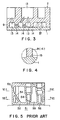
- This cylinder head is of integral construction and has a bottom wall part 52 the lower surface of which faces the combustion chamber 51 of the engine (not shown) and reinforcement wall parts 53 extending from the bottom wall part 52 in the upward direction or away from the combustion chamber 51.
- reinforcement wall parts 53 are formed reinforcement ribs 54, by which a cooling water passage 55 is formed and separated from other passages and spaces.
- air passages 56 extending to the bottom wall part 52 and exhaust gas passages 57 are formed by the reinforcement ribs 54.
- the entire conventional cylinder head has been formed integrally as a casting of aluminum, cast iron, or like material.
- the thermal stress ath can be expressed as follows. ⁇ th ⁇ E ⁇ q ⁇ h/ ⁇ ⁇ h, in which: E is the modulus of elasticity; ⁇ is the coefficient of linear expansion; ⁇ is the thermal conductivity; q is the heat flow density; and h is the wall thickness of the bottom wall part. From the above relationship, it is seen that, in order to prevent the rise of the thermal stress ⁇ th, it is necessary to keep the wall thickness h from increasing.
- the mechanical stress am can be expressed as follows. ⁇ m ⁇ p ⁇ (a/h) 2 , wherein: p is the maximum pressure within the cylinder; and a is the span of the reinforcement ribs 54. It is seen from the above relationship that, in order to prevent the mechanical stress from increasing, it is necessary that the span a of the reinforcement ribs 54 be small and that, at the same time, the wall thickness h be thick.
- the bottom wall part I and the reinforcement part 2 are formed separately but are adapted to be mutually joined. These parts can be joined by methods such as the diffusion welding method, the hot hydrostatic-press method, or the friction (pressure) welding method.
- the bottom wall part I and the reinforcement part 2 are formed from mutually different metals, the former being fabricated from a heat-resistant metal having a higher high-temperature strength and a lower thermal conductivity than the latter.
- a heat-resistant metal examples include nickel alloys, austenitic stainless steels, and martensitic stainless steels.
- the cylinder head illustrated in FIG. I has a bottom wall part I, the lower surface of which is disposed within and forms the ceiling of the combustion chamber, and a reinforcement part 2 on the side of the bottom wall part I remote from the combustion chamber.
- the bottom wall part I of disk shape is provided therethrough with holes 3, 3 for air intake valves, holes 4, 4 for exhaust valves, a hole 5 for a fuel valve, a hole 6 for a starting valve, and a hole 7 for a safety valve.
- the reinforcement part 2 has an outer cylinder 8 of hollow cylindrical shape and reinforcement ribs 9 partitioning the interior of the outer cylinder into divisional passages, the principal passages being air intake passages I0, exhaust passages II, a fuel passage I2, and cooling water passages 13.
- the bottom wall part l is preferably formed from a highstrength material having low thermal conductivity and high heat resistance.
- a nickel alloy such as Nimonic 80A (20 Cr - l Co - 2.5 Ti - I.3 Al); an austenitic stainless steel (25 Cr - 20 Ni); and martensitic stainless steel (I7 Cr - 7 Ni).
- the material is not necessarily limited to these metals, however.
- the bottom wall part I can be formed into the above described disk shape by a machining process such as turning but it can be formed also by casting or forging.
- the structure of the reinforcement part 2 is relatively complicated, it is preferably fabricated by casting a metal such as cast iron or cast steel, but it is also possible to produce a welded steel plate structure or to machine a steel block.
- the two parts I and 2 are integrally joined by joining the upper surface (as viewed in FIG. I) of the bottom wall part I to the lower end part, that is, the lower end surfaces of the outer cylinder 8 and the reinforcement ribs 9, of the reinforcement part 2.
- any of the aforementioned diffusion welding, hot hydrostatic-press, and friction (pressure) welding can be used. Thereafter, when necessary, the structure thus obtained is further machined or otherwise finished into a cylinder head.
- the span distances of the reinforcement ribs can be freely selected; that is, it can be set at an amply small value.
- the lower end part of the reinforcement part 2 is open before it is joined to the bottom wall part I, its fabrication by a process such as casting is facilitated, and its portions where stress concentration tends to occur can be removed.
- flaws such as casting defects can be detected by inspection and corrected prior to the joining of the two parts, it becomes possible to produce cylinder heads of high quality.
- the bottom wall part I which faces the combustion chamber, is formed from a high strength, heat-resistant material of low thermal conductivity as described hereinabove, its mechanical and thermal strengths are greatly improved, and at the same time it exhibits a heat-insulating function. Moreover, by forming the bottom wall part I from a high-strength material, it can be made thin so as to withstand increase in thermal stress. As a result, the durability and the thermal efficiency of the cylinder head, and therefore of the entire engine, are improved.
- the reinforcement part 2 is provided with a plurality of ribs l4,...,l4 in addition to the aforedescribed reinforcement ribs 9, and the cooling water passages I3 are thereby finely divided.
- the cylinder head of this embodiment is similar to that in the preceding embodiment Those parts in FIGS. 2 and 3 which are the same as or equivalent to corresponding parts in FIG. I are designated by like reference numerals, and description of such parts will not be repeated.
- the cooling water passage I3 is finely divided by the ribs l4,..., l4 particularly in the vicinity of the bottom wall part I.
- the span distances between the ribs 9 and I4 are made smaller, and at the same time the flow velocity of the cooling water passing through the passage I3 is increased, whereby its cooling effectiveness is improved.
- the composite cylinder head is illustrated schematically in the drawings for the sake of simplicity and merely for the purpose of description, it is to be understood that in actual practice, of course, the cylinder head is so adapted as to be attachable by known methods to related parts such as the cylinder liner and the cylinder block, which are not shown.
- the cylinder head according to this invention is of a composite construction wherein a bottom wall part and a reinforcement part are first formed as separate structures and are then joined to form an integral structure.
- the span distances of the reinforcement ribs previously provided in the reinforcement part can be set freely, that is, can be made amply small.
- the maximum pressure within the cylinder can be raised without causing an increase in the thermal and mechanical stresses thereby to increase the power output and thermal efficiency of the engine.
- one end of the reinforcement part prior to its joining to the bottom wall part is open, the fabrication of the reinforcement part is facilitated in the case where it is fabricated by casting, for example.
Landscapes
- Engineering & Computer Science (AREA)
- Chemical & Material Sciences (AREA)
- Combustion & Propulsion (AREA)
- Mechanical Engineering (AREA)
- General Engineering & Computer Science (AREA)
- Cylinder Crankcases Of Internal Combustion Engines (AREA)
Claims (7)
- Culasse pour moteur à combustion interne(a) comprenant une partie de paroi de fond (1) en regard de la chambre de combustion d'un cylindre, et une partie de renforcement (2) du côté de la partie de paroi de fond (1) opposé à la chambre de combustion;(b) la partie de paroi de fond (1) et la partie de renforcement (2) étant des structures formées séparément, jointes en une seule structure monobloc;(c) la partie de renforcement (2) comprenant des nervures (9) qui vont jusqu'à la partie de paroi de fond (1) et délimitent des passages d'eau de refroidissement (13); et(d) la surface supérieure de la partie de paroi de fond (1) et la surface inférieure de la partie de rentorcement (2) étant formées chacune d'une surface plane dans sa totalité de façon à fournir des surfaces de contact planes dans un seul plan,caractérisée en ce que(e) des nervures supplémentaires (14) sont disposées dans les passages d'eau de refroidissement (13) en divisant ainsi lesdits passages;(f) et la surface supérieure de la partie de paroi de fond (1) et la surface inférieure de la partie de renforcement (2), y compris les surfaces d'extrémité de nervure de toutes les nervures (9, 14) sont jointes les unes aux autres, les zones de surface de contact étant des surfaces de jonction directe.
- Une culasse suivant la revendication 1, dans laquelle la partie de paroi de fond (1) et la partie de renforcement (2) sont formées, respectivement, par des métaux différents l'un de l'autre.
- Une culasse suivant la revendication 2, dans laquelle la partie de paroi de fond (1) est formée d'un métal dont la résistance mécanique aux températures élevées est plus élevée et la conductivité thermique plus faible que celles du métal de la partie de renforcement (2).
- Une culasse suivant la revendication 3, dans laquelle la partie de paroi de fond (1) est formée d'un alliage de nickel.
- Une culasse suivant la revendication 3, dans laquelle la partie de paroi de fond (1) est formée d'un acier inoxydable austénitique.
- Une culasse suivant la revendication 3, dans laquelle la partie de paroi de fond (1) est formée d'un acier inoxydable martensitique.
- Une culasse suivant la revendication 3, dans laquelle la partie de renforcement (2) est faite en acier moulé.
Priority Applications (1)
| Application Number | Priority Date | Filing Date | Title |
|---|---|---|---|
| DE8686113450T DE3676704D1 (de) | 1986-09-30 | 1986-09-30 | Zusammengesetzter zylinderkopf fuer brennkraftmaschine. |
Applications Claiming Priority (1)
| Application Number | Priority Date | Filing Date | Title |
|---|---|---|---|
| JP60080925A JPS61237867A (ja) | 1985-04-15 | 1985-04-15 | 内燃機関のシリンダヘツド |
Publications (3)
| Publication Number | Publication Date |
|---|---|
| EP0262240A1 EP0262240A1 (fr) | 1988-04-06 |
| EP0262240B1 EP0262240B1 (fr) | 1990-12-27 |
| EP0262240B2 true EP0262240B2 (fr) | 1997-11-26 |
Family
ID=13732005
Family Applications (1)
| Application Number | Title | Priority Date | Filing Date |
|---|---|---|---|
| EP86113450A Expired - Lifetime EP0262240B2 (fr) | 1985-04-15 | 1986-09-30 | Culasse composée pour moteur à combustion interne |
Country Status (3)
| Country | Link |
|---|---|
| US (1) | US4774912A (fr) |
| EP (1) | EP0262240B2 (fr) |
| JP (1) | JPS61237867A (fr) |
Families Citing this family (13)
| Publication number | Priority date | Publication date | Assignee | Title |
|---|---|---|---|---|
| US6330872B1 (en) | 2000-08-16 | 2001-12-18 | Cummins Engine Company, Inc. | Cylinder head casting with gusset ribs |
| AT5142U1 (de) | 2000-12-18 | 2002-03-25 | Avl List Gmbh | Brennkraftmaschine |
| JP3730900B2 (ja) * | 2001-11-02 | 2006-01-05 | 本田技研工業株式会社 | 内燃機関 |
| ITTO20020063A1 (it) | 2002-01-22 | 2003-07-22 | Teksid Spa | Testa cilindri per un motore a combustione interna. |
| GB0220685D0 (en) * | 2002-09-05 | 2002-10-16 | Innogy Plc | A cylinder for an internal combustion engine |
| AT413859B (de) * | 2003-03-21 | 2006-06-15 | Avl List Gmbh | Brennkraftmaschine |
| US6874479B2 (en) * | 2003-03-21 | 2005-04-05 | Avl List Gmbh | Internal combustion engine |
| AT502971B1 (de) * | 2006-12-07 | 2008-05-15 | Avl List Gmbh | Zylinderkopf für eine brennkraftmaschine |
| EP2024116B1 (fr) | 2006-05-26 | 2011-11-02 | AVL List GmbH | Culasse de moteur à combustion interne |
| US20080237304A1 (en) * | 2007-03-30 | 2008-10-02 | Caterpillar Inc. | Engine component having friction welded inserts |
| CN103511116B (zh) * | 2013-10-10 | 2017-04-26 | 潍柴动力股份有限公司 | 一种发动机及其气缸盖 |
| FR3023590B1 (fr) | 2014-07-09 | 2020-10-02 | Mecachrome France | Culasse, element et semelle de moteur a piston. |
| US10113502B2 (en) | 2015-09-08 | 2018-10-30 | Ford Global Technologies, Llc | Cylinder head for an internal combustion engine |
Family Cites Families (23)
| Publication number | Priority date | Publication date | Assignee | Title |
|---|---|---|---|---|
| US1731228A (en) * | 1929-10-08 | burtnett | ||
| BE641870A (fr) * | ||||
| US1915970A (en) * | 1930-12-09 | 1933-06-27 | Gen Electric | Cylinder head |
| US2003571A (en) * | 1932-08-15 | 1935-06-04 | Bohn Aluminium & Brass Corp | Cylinder head for internal combustion engines |
| US2021942A (en) * | 1934-10-26 | 1935-11-26 | Int Motor Co | Welded head for internal combustion engines |
| US2730085A (en) * | 1950-12-19 | 1956-01-10 | Gen Motors Corp | Cylinder head |
| GB711739A (en) * | 1951-07-25 | 1954-07-07 | Lanova Ag | Improvements in or relating to cylinder heads for fuel-injection internal-combustionengines |
| US2963015A (en) * | 1958-02-24 | 1960-12-06 | Gen Motors Corp | Engine |
| US3081754A (en) * | 1961-02-14 | 1963-03-19 | Georges Raymond | Internal combustion engines, in particular of the constant pressure cycle type |
| US3960121A (en) * | 1971-06-16 | 1976-06-01 | Backus Devices, Incorporated | Engine combustion system |
| US3830209A (en) * | 1973-03-05 | 1974-08-20 | Robert Jones | Cylinder head and method of reconstructing same |
| DE2507073A1 (de) * | 1975-02-19 | 1976-09-02 | Jones Jun | Zylinderkopf und verfahren zur rekonstruktion desselben |
| JPS5196917A (fr) * | 1975-02-20 | 1976-08-25 | ||
| DE2514592C2 (de) * | 1975-04-03 | 1982-10-14 | Mtu Motoren- Und Turbinen-Union Friedrichshafen Gmbh, 7990 Friedrichshafen | Einzelzylinderkopf |
| US4018195A (en) * | 1975-10-06 | 1977-04-19 | General Motors Corporation | Insulated, high efficiency, low heat rejection, engine cylinder head |
| SU731013A1 (ru) * | 1978-08-14 | 1980-04-30 | Владимирский политехнический институт | Головка цилиндра дл двигател внутреннего сгорани |
| DE2937788A1 (de) * | 1979-09-19 | 1981-04-02 | Klöckner-Humboldt-Deutz AG, 5000 Köln | Leichtmetallzylinderkopf fuer brennkraftmaschinen |
| DE2946887C2 (de) * | 1979-11-21 | 1982-12-09 | Mtu Motoren- Und Turbinen-Union Friedrichshafen Gmbh, 7990 Friedrichshafen | Zylinderkopf für einen Dieselmotor |
| US4344390A (en) * | 1979-12-31 | 1982-08-17 | Cummins Engine Company, Inc. | Piston-cylinder assembly of an internal combustion engine |
| JPS6043234B2 (ja) * | 1981-07-27 | 1985-09-27 | 宮地電子株式会社 | 抵抗溶接に於ける品質管理装置 |
| US4453527A (en) * | 1981-12-28 | 1984-06-12 | Ford Motor Company | Insulated diesel engine combustion chamber |
| DE3307114C2 (de) * | 1983-03-01 | 1985-09-05 | Feldmühle AG, 4000 Düsseldorf | Zylinderkopf eines Kolbenmotors |
| DE3420571C1 (de) * | 1984-06-01 | 1986-01-09 | Alcan Aluminiumwerk Nürnberg GmbH, 6000 Frankfurt | Bauteil fuer Verbrennungsmotoren und Verfahren zu dessen Herstellung |
-
1985
- 1985-04-15 JP JP60080925A patent/JPS61237867A/ja active Pending
-
1986
- 1986-09-30 EP EP86113450A patent/EP0262240B2/fr not_active Expired - Lifetime
- 1986-09-30 US US06/913,234 patent/US4774912A/en not_active Expired - Fee Related
Also Published As
| Publication number | Publication date |
|---|---|
| EP0262240A1 (fr) | 1988-04-06 |
| US4774912A (en) | 1988-10-04 |
| EP0262240B1 (fr) | 1990-12-27 |
| JPS61237867A (ja) | 1986-10-23 |
Similar Documents
| Publication | Publication Date | Title |
|---|---|---|
| EP0262240B1 (fr) | Culasse composée pour moteur à combustion interne | |
| EP0217811B1 (fr) | Moteur possedant un bloc cylindres en plusieurs pieces | |
| US4083292A (en) | Piston with high top ring location | |
| US5586530A (en) | Valve seat insert | |
| US4838149A (en) | Pistons | |
| JPS5985448A (ja) | ピストンおよびその製法 | |
| US5954038A (en) | Combustion face insert | |
| US4034723A (en) | Insulated, high efficiency, low heat rejection, engine cylinder head | |
| JPH105976A (ja) | 内燃機関のピストンを製造する方法およびこの方法により製造されるピストン | |
| US4711456A (en) | Gasket for an internal combustion engine | |
| US3086505A (en) | Cylinder construction for internal combustion engines | |
| US4046114A (en) | Insulated, high efficiency, low heat rejection, engine cylinder head | |
| US20040182332A1 (en) | Liquid-cooled valve seat ring | |
| US4018195A (en) | Insulated, high efficiency, low heat rejection, engine cylinder head | |
| JPH08277746A (ja) | 内燃エンジン | |
| JPH0319383B2 (fr) | ||
| JP2561346Y2 (ja) | 内燃機関のシリンダヘッド | |
| JP2002227717A (ja) | 内燃機関 | |
| JPS6217347A (ja) | 内燃機関のピストン | |
| JP2592525Y2 (ja) | シリンダライナ | |
| CN112228237B (zh) | 一种用于四气阀柴油发动机的缸盖及柴油发动机 | |
| KR100634984B1 (ko) | 내연기관용 밸브 | |
| US2403001A (en) | Valve for internal combustion engines | |
| JP2656640B2 (ja) | ピストン組立体および所定の圧縮高さ対半径比を有するピストン部材 | |
| JPH04321759A (ja) | 内燃機関用ピストン |
Legal Events
| Date | Code | Title | Description |
|---|---|---|---|
| PUAI | Public reference made under article 153(3) epc to a published international application that has entered the european phase |
Free format text: ORIGINAL CODE: 0009012 |
|
| 17P | Request for examination filed |
Effective date: 19860930 |
|
| AK | Designated contracting states |
Kind code of ref document: A1 Designated state(s): CH DE GB LI |
|
| 17Q | First examination report despatched |
Effective date: 19881223 |
|
| GRAA | (expected) grant |
Free format text: ORIGINAL CODE: 0009210 |
|
| AK | Designated contracting states |
Kind code of ref document: B1 Designated state(s): CH DE GB LI |
|
| REF | Corresponds to: |
Ref document number: 3676704 Country of ref document: DE Date of ref document: 19910207 |
|
| PLBI | Opposition filed |
Free format text: ORIGINAL CODE: 0009260 |
|
| 26 | Opposition filed |
Opponent name: MTU MOTOREN- UND TURBINEN-UNION FRIEDRICHSHAFEN GM Effective date: 19910820 |
|
| PGFP | Annual fee paid to national office [announced via postgrant information from national office to epo] |
Ref country code: GB Payment date: 19950921 Year of fee payment: 10 |
|
| PGFP | Annual fee paid to national office [announced via postgrant information from national office to epo] |
Ref country code: DE Payment date: 19951127 Year of fee payment: 10 |
|
| PGFP | Annual fee paid to national office [announced via postgrant information from national office to epo] |
Ref country code: CH Payment date: 19951220 Year of fee payment: 10 |
|
| PG25 | Lapsed in a contracting state [announced via postgrant information from national office to epo] |
Ref country code: LI Effective date: 19960930 Ref country code: GB Effective date: 19960930 Ref country code: CH Effective date: 19960930 |
|
| APAC | Appeal dossier modified |
Free format text: ORIGINAL CODE: EPIDOS NOAPO |
|
| APAC | Appeal dossier modified |
Free format text: ORIGINAL CODE: EPIDOS NOAPO |
|
| PLAW | Interlocutory decision in opposition |
Free format text: ORIGINAL CODE: EPIDOS IDOP |
|
| REG | Reference to a national code |
Ref country code: CH Ref legal event code: PL |
|
| GBPC | Gb: european patent ceased through non-payment of renewal fee |
Effective date: 19960930 |
|
| PG25 | Lapsed in a contracting state [announced via postgrant information from national office to epo] |
Ref country code: DE Effective date: 19970603 |
|
| PLAW | Interlocutory decision in opposition |
Free format text: ORIGINAL CODE: EPIDOS IDOP |
|
| PUAH | Patent maintained in amended form |
Free format text: ORIGINAL CODE: 0009272 |
|
| STAA | Information on the status of an ep patent application or granted ep patent |
Free format text: STATUS: PATENT MAINTAINED AS AMENDED |
|
| 27A | Patent maintained in amended form |
Effective date: 19971126 |
|
| AK | Designated contracting states |
Kind code of ref document: B2 Designated state(s): CH DE GB LI |
|
| REG | Reference to a national code |
Ref country code: CH Ref legal event code: AEN Free format text: AUFRECHTERHALTUNG DES PATENTES IN GEAENDERTER FORM |
|
| APAH | Appeal reference modified |
Free format text: ORIGINAL CODE: EPIDOSCREFNO |