EP0262219B1 - Liquid metal ion source and alloy for ion emission of multiple ionic species - Google Patents
Liquid metal ion source and alloy for ion emission of multiple ionic species Download PDFInfo
- Publication number
- EP0262219B1 EP0262219B1 EP87903757A EP87903757A EP0262219B1 EP 0262219 B1 EP0262219 B1 EP 0262219B1 EP 87903757 A EP87903757 A EP 87903757A EP 87903757 A EP87903757 A EP 87903757A EP 0262219 B1 EP0262219 B1 EP 0262219B1
- Authority
- EP
- European Patent Office
- Prior art keywords
- arsenic
- boron
- alloy
- source
- ion
- Prior art date
- Legal status (The legal status is an assumption and is not a legal conclusion. Google has not performed a legal analysis and makes no representation as to the accuracy of the status listed.)
- Expired
Links
- 229910045601 alloy Inorganic materials 0.000 title claims abstract description 88
- 239000000956 alloy Substances 0.000 title claims abstract description 88
- 229910001338 liquidmetal Inorganic materials 0.000 title claims abstract description 24
- 229910052796 boron Inorganic materials 0.000 claims abstract description 59
- 229910052785 arsenic Inorganic materials 0.000 claims abstract description 58
- ZOXJGFHDIHLPTG-UHFFFAOYSA-N Boron Chemical compound [B] ZOXJGFHDIHLPTG-UHFFFAOYSA-N 0.000 claims abstract description 53
- RQNWIZPPADIBDY-UHFFFAOYSA-N arsenic atom Chemical compound [As] RQNWIZPPADIBDY-UHFFFAOYSA-N 0.000 claims abstract description 53
- 229910052698 phosphorus Inorganic materials 0.000 claims abstract description 26
- 239000011574 phosphorus Substances 0.000 claims abstract description 26
- WFKWXMTUELFFGS-UHFFFAOYSA-N tungsten Chemical compound [W] WFKWXMTUELFFGS-UHFFFAOYSA-N 0.000 claims abstract description 25
- 229910052721 tungsten Inorganic materials 0.000 claims abstract description 25
- 239000010937 tungsten Substances 0.000 claims abstract description 25
- OAICVXFJPJFONN-UHFFFAOYSA-N Phosphorus Chemical compound [P] OAICVXFJPJFONN-UHFFFAOYSA-N 0.000 claims abstract description 22
- KDLHZDBZIXYQEI-UHFFFAOYSA-N Palladium Chemical compound [Pd] KDLHZDBZIXYQEI-UHFFFAOYSA-N 0.000 claims description 67
- 229910052763 palladium Inorganic materials 0.000 claims description 32
- 229910052702 rhenium Inorganic materials 0.000 claims description 6
- WUAPFZMCVAUBPE-UHFFFAOYSA-N rhenium atom Chemical compound [Re] WUAPFZMCVAUBPE-UHFFFAOYSA-N 0.000 claims description 6
- 150000002500 ions Chemical class 0.000 abstract description 120
- 238000001704 evaporation Methods 0.000 abstract description 43
- 230000008020 evaporation Effects 0.000 abstract description 36
- 230000007797 corrosion Effects 0.000 abstract description 13
- 238000005260 corrosion Methods 0.000 abstract description 13
- 238000005468 ion implantation Methods 0.000 abstract description 7
- 239000004065 semiconductor Substances 0.000 abstract description 6
- 229910001096 P alloy Inorganic materials 0.000 abstract description 4
- 235000012431 wafers Nutrition 0.000 abstract 1
- 239000007788 liquid Substances 0.000 description 15
- PXHVJJICTQNCMI-UHFFFAOYSA-N Nickel Chemical compound [Ni] PXHVJJICTQNCMI-UHFFFAOYSA-N 0.000 description 14
- 229910052751 metal Inorganic materials 0.000 description 12
- 239000002184 metal Substances 0.000 description 12
- -1 metalloid ions Chemical class 0.000 description 12
- 238000002513 implantation Methods 0.000 description 9
- 238000010884 ion-beam technique Methods 0.000 description 9
- 238000001819 mass spectrum Methods 0.000 description 9
- 238000000605 extraction Methods 0.000 description 8
- 239000007943 implant Substances 0.000 description 8
- 238000013459 approach Methods 0.000 description 7
- 239000000203 mixture Substances 0.000 description 7
- 229910052759 nickel Inorganic materials 0.000 description 7
- 239000000758 substrate Substances 0.000 description 7
- 238000004519 manufacturing process Methods 0.000 description 6
- 238000009736 wetting Methods 0.000 description 6
- 239000000155 melt Substances 0.000 description 5
- 230000008018 melting Effects 0.000 description 5
- 238000002844 melting Methods 0.000 description 5
- 229910000521 B alloy Inorganic materials 0.000 description 4
- 239000003708 ampul Substances 0.000 description 4
- 238000010438 heat treatment Methods 0.000 description 4
- 239000000463 material Substances 0.000 description 4
- 238000000034 method Methods 0.000 description 4
- 229910002056 binary alloy Inorganic materials 0.000 description 3
- 230000008859 change Effects 0.000 description 3
- 239000002019 doping agent Substances 0.000 description 3
- 230000005496 eutectics Effects 0.000 description 3
- 239000010453 quartz Substances 0.000 description 3
- 239000000523 sample Substances 0.000 description 3
- VYPSYNLAJGMNEJ-UHFFFAOYSA-N silicon dioxide Inorganic materials O=[Si]=O VYPSYNLAJGMNEJ-UHFFFAOYSA-N 0.000 description 3
- 238000012360 testing method Methods 0.000 description 3
- XUIMIQQOPSSXEZ-UHFFFAOYSA-N Silicon Chemical compound [Si] XUIMIQQOPSSXEZ-UHFFFAOYSA-N 0.000 description 2
- 239000000470 constituent Substances 0.000 description 2
- 238000010276 construction Methods 0.000 description 2
- 230000007423 decrease Effects 0.000 description 2
- 230000000694 effects Effects 0.000 description 2
- 230000005684 electric field Effects 0.000 description 2
- 230000005686 electrostatic field Effects 0.000 description 2
- 238000010348 incorporation Methods 0.000 description 2
- 229910052752 metalloid Inorganic materials 0.000 description 2
- 230000008569 process Effects 0.000 description 2
- 229910052710 silicon Inorganic materials 0.000 description 2
- 239000010703 silicon Substances 0.000 description 2
- 239000007787 solid Substances 0.000 description 2
- QKPDTDDCZSIQKB-UHFFFAOYSA-N [As].[P].[B] Chemical compound [As].[P].[B] QKPDTDDCZSIQKB-UHFFFAOYSA-N 0.000 description 1
- 230000009471 action Effects 0.000 description 1
- 230000002411 adverse Effects 0.000 description 1
- 238000005275 alloying Methods 0.000 description 1
- 229910052787 antimony Inorganic materials 0.000 description 1
- WATWJIUSRGPENY-UHFFFAOYSA-N antimony atom Chemical compound [Sb] WATWJIUSRGPENY-UHFFFAOYSA-N 0.000 description 1
- 229910001423 beryllium ion Inorganic materials 0.000 description 1
- 230000015572 biosynthetic process Effects 0.000 description 1
- QDWJUBJKEHXSMT-UHFFFAOYSA-N boranylidynenickel Chemical compound [Ni]#B QDWJUBJKEHXSMT-UHFFFAOYSA-N 0.000 description 1
- ZXQKSCQCQBPHOZ-UHFFFAOYSA-N boron;platinum Chemical compound [Pt]#B ZXQKSCQCQBPHOZ-UHFFFAOYSA-N 0.000 description 1
- 150000001875 compounds Chemical class 0.000 description 1
- 230000003750 conditioning effect Effects 0.000 description 1
- 238000001816 cooling Methods 0.000 description 1
- 230000003247 decreasing effect Effects 0.000 description 1
- 230000002939 deleterious effect Effects 0.000 description 1
- 230000006866 deterioration Effects 0.000 description 1
- 238000011161 development Methods 0.000 description 1
- 238000007598 dipping method Methods 0.000 description 1
- 238000004090 dissolution Methods 0.000 description 1
- 238000005516 engineering process Methods 0.000 description 1
- 238000002474 experimental method Methods 0.000 description 1
- 239000012530 fluid Substances 0.000 description 1
- 230000005484 gravity Effects 0.000 description 1
- 230000005764 inhibitory process Effects 0.000 description 1
- 230000003993 interaction Effects 0.000 description 1
- 230000005499 meniscus Effects 0.000 description 1
- 150000001455 metallic ions Chemical class 0.000 description 1
- 150000002738 metalloids Chemical class 0.000 description 1
- 238000002156 mixing Methods 0.000 description 1
- 238000012986 modification Methods 0.000 description 1
- 230000004048 modification Effects 0.000 description 1
- 230000003287 optical effect Effects 0.000 description 1
- 238000012545 processing Methods 0.000 description 1
- 239000000376 reactant Substances 0.000 description 1
- 238000007711 solidification Methods 0.000 description 1
- 230000008023 solidification Effects 0.000 description 1
- 239000000126 substance Substances 0.000 description 1
- 230000002459 sustained effect Effects 0.000 description 1
Images
Classifications
-
- H—ELECTRICITY
- H01—ELECTRIC ELEMENTS
- H01J—ELECTRIC DISCHARGE TUBES OR DISCHARGE LAMPS
- H01J37/00—Discharge tubes with provision for introducing objects or material to be exposed to the discharge, e.g. for the purpose of examination or processing thereof
- H01J37/02—Details
- H01J37/04—Arrangements of electrodes and associated parts for generating or controlling the discharge, e.g. electron-optical arrangement or ion-optical arrangement
- H01J37/08—Ion sources; Ion guns
-
- H—ELECTRICITY
- H01—ELECTRIC ELEMENTS
- H01J—ELECTRIC DISCHARGE TUBES OR DISCHARGE LAMPS
- H01J27/00—Ion beam tubes
- H01J27/02—Ion sources; Ion guns
- H01J27/26—Ion sources; Ion guns using surface ionisation, e.g. field effect ion sources, thermionic ion sources
Definitions
- This invention relates to liquid metal ion sources, and, more particularly, to alloys used to evaporate multiple ionic species from such sources.
- Such an ion source is known from G-A-2,087,139 and comprises emission means for emitting positively charged ionic species and source means for supplying to said emission means the ionic species to be emitted, said species being provided in a substantially nickel-free alloy.
- Liquid metal ion sources provide high current density beams of metallic ions from a source having a small virtual source size. Such high current and small source size are required when the ion beam is to be focused with a high resoluton of, for example, less than 1 micrometer spot size and utilized in applications such as fabrication of semiconductor microcircuits by ion implantation.
- the high current density and small virtual source size are achieved by emitting the ions from a substrate having a sharp point, such as the point of a needle.
- a needle is covered with a layer of liquid ion source metal, and a cusp in the liquid metal at the point of the needle is created by the application of an electrostatic extraction field.
- the ions are emitted from this tiny cusp. As the ions are emitted and the amount of liquid alloy decreases, more liquid metal flows from a reservoir down the needle to the cusp to replenish that emitted.
- a species to be implanted typically resides in a liquid alloy while in the reservoir and on the needle.
- This alloy must be heated to at least its melting point and remain in the molten state for long periods of time during ion implantation runs.
- species which have high vapor pressures can be lost from the alloy in significant amounts, so that the alloy composition changes over time.
- This change in the composition of the ion source alloy over time can be highly significant and deleterious in the fabrication of semiconductor microcircuits, due to the change in the current density of the ionic species to be implanted in the semiconductor chip.
- the long period of contact between the molten alloy and the emission elements of the liquid metal ion source, including the reservoir and the needle substrate, can cause corrosion and failure of these elements.
- the lifetime of a liquid metal ion source is often limited by the attack and corrosion of the emission elements by the molten alloy, and such corrosion can undesirably change the emission characteristics of an operating ion source over time.
- An alternative approach is to form an alloy of the desired ion evaporation species with other metal of metalloid constituents chosen so that the melting point of the alloy is lowered below that of the pure species, and further so that the corrosion of the emission elements by the liquid alloy is reduced, as compared with the unalloyed pure evaporation species.
- the alloy has been chosen to be of eutectic or near-euctec- tic composition.
- a eutectic reaction depresses the liquidus temperature of any of the reactants, to an intermediate melting point, which is the composition at which that liquid can exist to the lowest temperature without formation of any solid.
- a eutectic or near-eutectic composition in a liquid metal ion source allows the source to be operated with the liquid alloy at a minimum temperature, thereby reducing the corrosion rate of the alloy on the evaporation source elements.
- Both the desired species and the alloying elements are ion evaporated from the source, but the desired species may be selected from implantation using a velocity filter which acts as a mass separator to pass only the selected species.
- a further important consideration in the selection of liquid metal ion source alloys is the wetting of the source elements by the alloy.
- the alloy must wet the evaporation elements sufficiently so that it forms a liquid layer on the evaporation elements, and so that additional metal can flow from the reservoir to the needle tip during continuous evaporation runs.
- the attainment of sufficiently good wettability and minimization of corrosion are difficult to achieve simultaneously in many instances.
- an ion source capable of simultaneously evaporating arsenic ions for n-type shallow, heavy implants, and boron for p-type implants. It would also be desirable to have a source capable of implanting arsenic and boron ions, and in addition implanting phosphoros ions for n-type deep implants. There have been proposed no ion sources capable of simultaneously ion evaporating arsenic, boron and phosphorus, and previously reported sources evaporating both boron and arsenic had unacceptably low yields of one species and/or short lifetimes.
- Sources are known to ion evaporate individual ions, such as arsenic, but no sources have been proposed for simultaneously evaporating the combinations of ions indicated above.
- Experiments and theoretical studies have indicated that simultaneous, continuous evaporation of multiple ionic species of interest would be difficult or impossible, since the ions inherently exhibit different evaporation threshold voltages.
- the evaporation threshold voltage for boron ions is approximately twice that of arsenic ions, and prior work such as disclosed in GB-A-2,087,139 corresponding with US-A4,367,429 suggests that simultaneous evaporation of such differing species would not occur.
- the usual considerations of wetting and inhibition of corrosion of the emission elements must be satisfied in a more complex alloy.
- the present invention provides a liquid metal ion source and alloy for the simultaneous evaporation of multiple ionic species of use in the ion implantation of silicon-based devices.
- a source for the simultaneous ion evaporation of arsenic and boron, arsenic and phosphorus, or arsenic, boron and phosphorus wet the materials of construction of the emission elements of the ion source, allowing continuous flow operation.
- the ion evaporation process is sufficiently stable that control of evaporation may be achieved in standard apparatus.
- the corrosive effects are sufficiently small that the ion source may be operated for long periods of time in commercial ion implantation operations.
- a liquid metal ion source comprises emission means for emitting positively charged ionic species; and source means for supplying to the emission means the ionic species to be emitted, the species being provided in a substantially nickel-free alloy consisting essentially of palladium, arsenic, and at least one element to be co-emitted, the element being selected from the group consisting of boron, phosphorus, and combinations thereof.
- the alloy is preferably at least 50 atomic percent palladium, and most preferably about 70 atomic percent palladium.
- one such alloy for the simultaneous evaporation of arsenic and boron includes palladium, arsenic and boron.
- a preferred alloy of this type contains about 70 atomic percent palladium, 16 atomic percent arsenic, and 14 atomic percent boron.
- an alloy useful for the simultaneous evaporation of arsenic, boron and phosphorus includes palladium, arsenic, boron and phosphorus. Most preferably, this alloy contains about 73 atomic percent palladium, 8 atomic percent arsenic, 7 atomic percent boron, and 12 atomic percent phosphorus.
- the alloys providing the species for ion evaporation are used in conjunction with ion sources having a conventional construction, wherein the emission means is a needle emitter and the source means is a U-shaped heater element in which a reservoir of the molten metal is formed by resistance heating.
- the source alloy containing the species for ionic evaporation is prepared by any convenient method and then loaded into the ion source in a finely divided form. The source is heated by the passage of electrical current through the U-shaped heater element, and ions are drawn off the tip of the needle by an extraction electrode, thence passing into an ion optical column or other appropriate apparatus for conditioning the ion beam and controlling the implantation.
- the ion source simultaneously evaporates multiple species, a single species may be selected for implantation by passing the ion beam through a mass separator so that only the selected species is allowed to impact the target.
- the ion source of the present invention represents an important advance in the development of commercial ion implantation technology.
- a single ion source may be used for the evaporation of multiple ionic species of interest, so that the source does not have to be changed between processing steps involving implantation of different ions.
- the source is stable with a reasonably long operating lifetime.
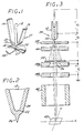
- the present invention relates to a liquid metal ion source, indicated generally by the numerical 10 in FIGURE 1.
- the ion source 10 includes an ion evaporation substrate needle 12 typically having a tip radius of less than about 20 micrometers and an apex half angle of less than about 49.5°C, which extends through a hole (not visible) at the lower end of a generally U-shaped heater element 14.
- the heater element 14 is in the form of a U-shaped ribbon which may incorporate an embossed crease 16 in each leg thereof to increase the columnar strength of the heater element 14. If used, the crease 16 approaches an apex bend 18 at the lower end of the heater element 14, but does not enter the region of the apex bend 18 itself.
- Ion source alloy in powdered, chip, or otherwise finely divided form
- V H an electrical current, produced by a voltage V H , is passed through this heater element 14, so that the alloy melts and naturally forms a reservoir 19 of liquid metal in the apex bend 18 of the heater element 14.
- the reservoir 19 remains anchored in the apex bend 18 under the influence of gravity because surface tension tends to minimize the meniscus 20 of liquid metal.
- the needle 12 passes through a non-circular hole (not visible) in the heater element 14, so designed as to allow liquid metal to flow to a needle tip 22 yet still retain the needle 12.
- heating of the heater element 14 melts the metal in the reservoir 19 to wet the inner surface of the apex bend 18 of the heater element 14.
- the molten metal conducts heat to the needle 12 so that the molten metal is wet to the needle 12.
- the molten metal flows along the needle 12 to the needle tip 22, for subsequent ion evaporation.
- the liquid source metal flows from the reservoir 19 located in the apex bend 18 toward the tip 22 of the needle 12, forming a liquid layer 24 along the tip 22 of the needle 12.
- the action of an applied external electrostatic field, produced by an extraction electrode 28 draws the liquid layers 24 downwardly to form a cusp 26.
- the ions emitted by the ion source 10 are preferably emitted only from the cusp 26, located adjacent to the extreme end of the needle tip 22, so that ions appear to emanate from a point source of extremely small dimensions.
- Positively charged ions are drawn from the cusp 26 by an electrostatic field set up between the ion source 10 and the extraction electrode 28 through the application of a voltage V E . Ions leave the cups 26 and pass through a hole 27 in the extraction electrode 28. With this configuration, the current density of emitted ions at the cusp 26 can be very large, typically on the order of 10 4 (A/cm 2 . sr) (amps per square centimeter per steradian).
- the liquid layer 24 must flow from the reservoir 19 located in the apex bend 18 down the surface of the needle 12 to the cusp 26, for emission to be initiated and sustained.
- wetting is too extensive, a chemical interaction between the molten metal and the solid substrate can result in corrosion of the substrate, so that portions of the substrate are dissolved.
- pits, cracks, or fissures can form in the needle tip 22, the needle 12 may fail entirely, or multiple cusps may be formed due to the corrosion geometry, so that the source 10 cannot be properly focused.
- FIGURE 3 illustrates one important use of liquid metal ion sources of the type illustrated in FIGURES 1 and 2.
- the ion source 10 is mounted in a scanning ion probe 30.
- the extraction electrode 28, which is negatively biased with respect to the needle 12 by the voltage V E , draws ions out of the cusp 26, for form an ion beam 32.
- a small portion of this beam 32 is allowed to pass through an aperture 34 into the optics section of the scanning ion probe 30.
- a transmitted beam 36 emerging from the aperture 34 is passed through accelerating electrodes 38 which increase the energy of the beam 36, as the second accelerating electrode 38b is negatively biased with respect to the first electrode 38a by a voltage V L .
- the converging beam 36 then passes through electrostatic deflection electrodes 40 wherein the beam is deflected from side-to-side to move in a scanning fashion across the surface of a target 42.
- the transmitted beam 36 can then be used to write various patterns upon the surface of the target 42 in the form of ion implanted zones of controllable shape and type.
- the beam may also be used to ion machine very narrow grooves of very small holes.
- a secondary electron detector not shown
- the beam may be used to image the target in a fashion similar to that of a scanning electron microscope.
- a secondary ion mass spectrometer not shown
- the microcomposition of a very small region located on the target 42 may be analyzed in both a qualitative and quantitative manner.
- E x B mass separator 44 to deflect ions of differing masses by differing amounts.
- the mass separator 44 is preferably a Wien velocity filter which acts as a mass separator because of the very low energy spread of the beam obtained from a liquid metal ion source when properly operated.
- the mass separator 44 is preferably positioned between the extraction electrode 28 and the aperture 34, and includes means to produce magnetic and electrical fields within the mass separator 44. The fields within the mass separator 44 deflect the moving ions passing therethrough by amounts which are related to the mass, velocity and charge of the ions in the beam.
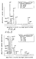
- FIGURES 4 and 5 illustrate the mass spectra of beams of ions from palladium-arsenic-boron and palladium-arsenic-boron-phosphorus sources, respectively, plotting the relative target currents as a function of the relative plate voltage of the mass separator 44. It is apparent that ions of particular types and charge states may be selected by setting the plate voltage to correspond to the peak for the selected ion.
- the source means containing the species to be evaporated as ions includes an alloy consisting essentially of palladium, arsenic and boron, the alloy being substantially free of any nickel.
- the ion source is operable and stable in emitting both boron and arsenic, but exhibits a relatively short lifetime of 6-10 hours. Since source operating lifetimes of at least 50 hours are desirable, it is preferred that a higher palladium content be utilized. Specifically, palladium contents of about 70 atomic percent have been found highly satisfactory to produce stable, long lifetime ion sources, as will be described fully in the examples present below.
- FIGURE 4 illustrates the mass spectrum for a source having a rhenium heater ribbon and a tungsten emitter needle. Usable currents of both boron and arsenic, in each of several ionic forms, are obtained. The beam is approximately stoichiometric in palladium content, although the arsenic content of the beam is measured to be greaterthan that of the source alloy and the boron content of the beam is measured to be less than that of the source alloy.
- the angular current intensities are determined to be 5 pA (micro amps) per steradian for AsH and 1.5 pA (micro amps) per steradian for 11 B + , at a total extraction current of 20 pA (microamps).
- the source means containing the species to be evaporated as ions is an alloy consisting essentially of palladium, arsenic, boron and phosphorus, and is substantially nickel-free.
- a first presently preferred source alloy contains about 73 atomic percent palladium, 8 atomic percent arsenic, 7 atomic percent boron, and 12 atomic percent phosphorus; and a second preferred alloy contains about 64 atomic percent palladium, 11 atomic percent arsenic, 9 atomic percent boron, and 16 atomic percent phosphorus.
- the second preferred alloy When evaporated from an ion source including a tungsten needle and tungsten heater, the second preferred alloy produces the mass spectrum illustrated in FIGURE 5.
- the source is stable with a relatively long lifetime.
- the source for arsenic, boron and phosphorus ions produces useable currents of all three species, with the arsenic and boron composition of the beam slightly greater than that of the liquid source alloy, and the boron content of the beam slightly less than that of the source alloy. It would be desirable that the beam composition be identical with that of the molten source alloy, but again it is unexpected that usable currents of all three species are obtained simultaneously.
- Phosphorus is an n- dopant used to adjust the threshold for FET devices and to set a deep well for subsequent base implants in vertical npn bipolar devices.
- a high fraction of P ++ is desirable, and the ion source of the present invention provides a usable current of P ++ ions.
- the source alloy be substantially free of nickel. Tests with palladium- nickel-arsenic-boron alloys have indicated that arsenic and boron can be simultaneously emitted from this alloy, but that the nickel in such a molten source alloy tends to corrode the tungsten emitter needles and ribbons very rapidly, greatly limiting the lifetime of the ion source. It had previously been thought that nickel must be included in such source alloys to insure wetting of the emission elements by the liquid source alloy, but it has been found that the palladium-arsenic-boron and palladium-arsenic-boron-phosphorus alloys of the present invention are acceptably wetted to the emission needles and ribbons, without corrosively attacking them.
- the operability, wettability, and long lifetime of the source alloys of the present invention cannot be predicted from the behaviour of related binary alloys. It is well known that platinum-boron and nickel-boron alloys chemically react rapidly with tungsten and rhenium, to rapidly corrode these candidate emitter and ribbon materials. Related binary alloys also do not produce acceptable wetting characteristics. An alloy of 75 atomic percent palladium and 25 atomic percent phosphorus is too fluid to be used as a source alloy, since when melted such an alloy runs to the tip of the needle emitter and then drops off. An alloy of 72 atomic percent palladium and 28 atomic percent boron has too high a viscosity for use as a source alloy, since such a binary alloy forms balls on the needle and will not flow to the needle tip, resulting in improper emission characteristics.
- Ion source alloys in accordance with the invention may be prepared and supplied to the emission means in any appropriate manner.
- pieces of the constituents are placed into a crucible and melted.
- the emission means can be loaded by dipping it into the melt. This approach is not preferred, since arsenic is easily lost from unconfined melts, and because of the expense of preparing the alloys.
- a palladium-arsenic-boron alloy can be prepared by mixing appropriate fractions of palladium-arsenic and palladium-boron alloys that have been previously prepared. After solidification and cooling of the melt, the alloy may be readily broken into small pieces which can then be placed into the ion source, and supported in the U-shaped apex bend 18 of the heater element ribbon 14.
- a palladium-arsenic-boron-phosphorus alloy is prepared by combining appropriate amounts of powdered alloys of palladium-arsenic, palladium-boron, and palladium-phosphorus.
- An alloy containing 50 atomic percent palladium, 25 atomic percent arsenic and 25 atomic percent boron was prepared, and ion evaporated using a tungsten needle and a tungsten heater ribbon.
- the ion source operated well, with sufficient stability for a mass spectrum of the ion beam to be obtained. Both boron and arsenic were observed in the beam. However, the tungsten needle and heater ribbon were corroded in 6-10 hours, which is marginally acceptable for a commercial ion source.
- a source alloy of 70 atomic percent palladium, 16 atomic percent arsenic and 14 atomic percent boron was prepared by heating the appropriate fractions of powdered Rd 2 As and PdB alloys in a quartz ampoule. The resulting allow was broken into small pieces and loaded into an ion source having a tungsten needle and a tungsten heater ribbon. The source ran well, with good stability. Both boron and arsenic were observed in the mass spectrum of the beam. After about 20 hours operation, however, the boron content in the ion beam decreased to about 30 perent of its original value. Additional alloy was then loaded into the ion source, but the boron content of the beam was not increased significantly. It is believed that the decrease in the boron fraction in the beam is due to dissolution of boron into the tungsten heater ribbon (which operates at a higher temperature than the tungsten needle).
- Example 2 was repeated, except that the tungsten heater ribbon was replaced by a rhenium heater ribbon.
- the resulting ion source was stable, and both boron and arsenic were observed in the mass spectrum of the beam, as illustrated in FIGURE 4.
- the boron content remained substantially constant with time, probably due to the lower rate of attack of liquid metals on rhenium than on tungsten.
- An alloy containing 40 atomic percent palladium, 40 atomic percent nickel, 10 atomic percent arsenic, and 10 atomic percent boron was fabricated. This alloy is not within the scope of the invention, in that it contains a substantial nickel content.
- An ion source was prepared using this source alloy, together with a tungsten needle and tungsten heater ribbon. Although the ion source did operate, it was unacceptable for two reasons. First, the presence of nickel resulted in rapid corrosion of the tungsten and failure of the ion source. Second, the amount of boron found in the ion beam was unacceptably low, and therefore this ion source (having less than 50 atomic percent palladium) was unacceptable for the simultaneous ion evaporation of arsenic and boron.
- a source alloy of 64 atomic percent palladium, 11 atomic percent arsenic, 9 atomic percent boron, and 16 atomic percent phosphorus was prepared by heating the appropriate ratios of previously obtained powdered alloys of Pd 2 As, Pd. 72 B. 28 and Pd 3 P in a sealed quartz ampoule. The resulting alloy was broken into pieces and loaded into an ion source having a tungsten needle and a tungsten heater ribbon. A stable mass spectrum was obtained, as illustrated in FIGURE 5, including a significant amount of pH ions. The source operated in a stable fashion, and there was no apparent deterioration of the tungsten source elements.
- the present invention provides liquid metal ion sources for the simultaneous ion evaporation of arsenic and boron ions, and of arsenic, boron and phosphorus ions.
- the ability to evaporate combinations of different ions of practical interest in the semiconductor industry is highly significant, in that self- aligned ion implants can be accomplished with a high degree of accuracy, spatial resolution and reproducibility, because the ion beam source need not be changed in order to implant the various ionic species. That is, a source evaporating two or more elements simultaneously can be adjusted to implant a first evaporated species and then a second evaporated species without changing the operation of the source, and only by changing the settings of the mass separator.
- the alloys of the present invention allow the simultaneous ion beam evaporation and implantation of the ionic species of interest with a high degree of operating stability, and high beam fractions of each of the ionic species. Moreover, the sources have extended operating lifetimes, which are necessary for commercial operations.
- the source alloys can be ion evaporated from emitter needles and ribbons, or other source elements, made of conventional source materials such as tungsten and rhenium, without the need for the expensive specialized fabrication of exotic materials.
- the present invention provides an ion source meeting the requirements of commercial operations, which is capable of simultaneously ion evaporating arsenic and boron, or arsenic, boron and phosphorus.
Landscapes
- Chemical & Material Sciences (AREA)
- Engineering & Computer Science (AREA)
- Combustion & Propulsion (AREA)
- Analytical Chemistry (AREA)
- Electron Sources, Ion Sources (AREA)
Applications Claiming Priority (2)
| Application Number | Priority Date | Filing Date | Title |
|---|---|---|---|
| US06/851,755 US4670685A (en) | 1986-04-14 | 1986-04-14 | Liquid metal ion source and alloy for ion emission of multiple ionic species |
| US851755 | 1992-03-16 |
Publications (2)
| Publication Number | Publication Date |
|---|---|
| EP0262219A1 EP0262219A1 (en) | 1988-04-06 |
| EP0262219B1 true EP0262219B1 (en) | 1990-04-25 |
Family
ID=25311600
Family Applications (1)
| Application Number | Title | Priority Date | Filing Date |
|---|---|---|---|
| EP87903757A Expired EP0262219B1 (en) | 1986-04-14 | 1987-03-09 | Liquid metal ion source and alloy for ion emission of multiple ionic species |
Country Status (5)
| Country | Link |
|---|---|
| US (1) | US4670685A (cg-RX-API-DMAC7.html) |
| EP (1) | EP0262219B1 (cg-RX-API-DMAC7.html) |
| JP (1) | JPS63503023A (cg-RX-API-DMAC7.html) |
| IL (1) | IL81956A (cg-RX-API-DMAC7.html) |
| WO (1) | WO1987006390A2 (cg-RX-API-DMAC7.html) |
Families Citing this family (16)
| Publication number | Priority date | Publication date | Assignee | Title |
|---|---|---|---|---|
| JPH0685309B2 (ja) * | 1985-12-13 | 1994-10-26 | 株式会社日立製作所 | 液体金属イオン源 |
| US4907422A (en) * | 1988-09-30 | 1990-03-13 | The Manitowoc Company, Inc. | Harvest cycle refrigerant control system |
| US4994711A (en) * | 1989-12-22 | 1991-02-19 | Hughes Aircraft Company | High brightness solid electrolyte ion source |
| US5447763A (en) * | 1990-08-17 | 1995-09-05 | Ion Systems, Inc. | Silicon ion emitter electrodes |
| US5149976A (en) * | 1990-08-31 | 1992-09-22 | Hughes Aircraft Company | Charged particle beam pattern generation apparatus and method |
| US6022258A (en) * | 1996-03-27 | 2000-02-08 | Thermoceramix, Llc | ARC chamber for an ion implantation system |
| US5914494A (en) * | 1996-03-27 | 1999-06-22 | Thermoceramix, Llc | Arc chamber for an ion implantation system |
| US5857889A (en) * | 1996-03-27 | 1999-01-12 | Thermoceramix, Llc | Arc Chamber for an ion implantation system |
| US6239440B1 (en) | 1996-03-27 | 2001-05-29 | Thermoceramix, L.L.C. | Arc chamber for an ion implantation system |
| FR2806527B1 (fr) | 2000-03-20 | 2002-10-25 | Schlumberger Technologies Inc | Colonne a focalisation simultanee d'un faisceau de particules et d'un faisceau optique |
| US6914386B2 (en) * | 2003-06-20 | 2005-07-05 | Applied Materials Israel, Ltd. | Source of liquid metal ions and a method for controlling the source |
| US9275823B2 (en) | 2012-03-21 | 2016-03-01 | Fei Company | Multiple gas injection system |
| US9105438B2 (en) | 2012-05-31 | 2015-08-11 | Fei Company | Imaging and processing for plasma ion source |
| JP6238978B2 (ja) | 2012-06-29 | 2017-11-29 | エフ・イ−・アイ・カンパニー | 多種イオン源 |
| US9899181B1 (en) | 2017-01-12 | 2018-02-20 | Fei Company | Collision ionization ion source |
| US9941094B1 (en) | 2017-02-01 | 2018-04-10 | Fei Company | Innovative source assembly for ion beam production |
Family Cites Families (2)
| Publication number | Priority date | Publication date | Assignee | Title |
|---|---|---|---|---|
| US4367429A (en) * | 1980-11-03 | 1983-01-04 | Hughes Aircraft Company | Alloys for liquid metal ion sources |
| JPS59191225A (ja) * | 1983-04-15 | 1984-10-30 | Hitachi Ltd | 液体金属イオン種合金 |
-
1986
- 1986-04-14 US US06/851,755 patent/US4670685A/en not_active Expired - Lifetime
-
1987
- 1987-03-09 EP EP87903757A patent/EP0262219B1/en not_active Expired
- 1987-03-09 JP JP62503518A patent/JPS63503023A/ja active Granted
- 1987-03-09 WO PCT/US1987/000455 patent/WO1987006390A2/en not_active Ceased
- 1987-03-22 IL IL81956A patent/IL81956A/xx not_active IP Right Cessation
Also Published As
| Publication number | Publication date |
|---|---|
| EP0262219A1 (en) | 1988-04-06 |
| US4670685A (en) | 1987-06-02 |
| WO1987006390A3 (en) | 1987-11-05 |
| WO1987006390A2 (en) | 1987-10-22 |
| IL81956A0 (en) | 1987-10-20 |
| JPS63503023A (ja) | 1988-11-02 |
| JPH0542095B2 (cg-RX-API-DMAC7.html) | 1993-06-25 |
| IL81956A (en) | 1990-11-29 |
Similar Documents
| Publication | Publication Date | Title |
|---|---|---|
| EP0262219B1 (en) | Liquid metal ion source and alloy for ion emission of multiple ionic species | |
| US5034612A (en) | Ion source method and apparatus | |
| US7420181B2 (en) | Liquid metal ion gun | |
| JPH0685309B2 (ja) | 液体金属イオン源 | |
| US4687938A (en) | Ion source | |
| EP0706199B1 (en) | Novel high brightness point ion sources using liquid ionic compounds | |
| EP0217951B1 (en) | Manufacture of liquid metal ion source | |
| US4551650A (en) | Field-emission ion source with spiral shaped filament heater | |
| JPS58163135A (ja) | イオン源 | |
| US4775818A (en) | Liquid metal ion source and alloy | |
| US4624833A (en) | Liquid metal ion source and apparatus | |
| US4629931A (en) | Liquid metal ion source | |
| US5006715A (en) | Ion evaporation source for tin | |
| EP0399374A1 (en) | Ion source method and apparatus | |
| GB2424754A (en) | A focused ion beam generator | |
| JPS61248335A (ja) | 液体金属イオン源 | |
| Umemura et al. | Phosphorus liquid metal ion source using a Pt–P–Sb alloy | |
| JPS58137943A (ja) | イオン源 | |
| Graeme | Liquid Metal Ion Sources | |
| Umemura et al. | Development of an arsenic liquid-metal ion source | |
| Higuchi‐Rusli et al. | High current Cu3P liquid metal ion source using a novel extractor configuration | |
| JPH02215026A (ja) | 液体金属イオン源 | |
| JPS60167231A (ja) | 液体金属イオン源 | |
| JPH06101296B2 (ja) | 液体金属イオン源 | |
| JPS61267222A (ja) | 液体金属イオン源 |
Legal Events
| Date | Code | Title | Description |
|---|---|---|---|
| PUAI | Public reference made under article 153(3) epc to a published international application that has entered the european phase |
Free format text: ORIGINAL CODE: 0009012 |
|
| 17P | Request for examination filed |
Effective date: 19871214 |
|
| AK | Designated contracting states |
Kind code of ref document: A1 Designated state(s): CH DE FR GB IT LI NL SE |
|
| 17Q | First examination report despatched |
Effective date: 19890217 |
|
| RAP1 | Party data changed (applicant data changed or rights of an application transferred) |
Owner name: OREGON GRADUATE CENTER Owner name: GOVERNMENT OF THE UNITED STATES Owner name: HUGHES AIRCRAFT COMPANY |
|
| GRAA | (expected) grant |
Free format text: ORIGINAL CODE: 0009210 |
|
| AK | Designated contracting states |
Kind code of ref document: B1 Designated state(s): CH DE FR GB IT LI NL SE |
|
| REF | Corresponds to: |
Ref document number: 3762471 Country of ref document: DE Date of ref document: 19900531 |
|
| ET | Fr: translation filed | ||
| ITF | It: translation for a ep patent filed | ||
| PLBE | No opposition filed within time limit |
Free format text: ORIGINAL CODE: 0009261 |
|
| STAA | Information on the status of an ep patent application or granted ep patent |
Free format text: STATUS: NO OPPOSITION FILED WITHIN TIME LIMIT |
|
| 26N | No opposition filed | ||
| NLT1 | Nl: modifications of names registered in virtue of documents presented to the patent office pursuant to art. 16 a, paragraph 1 |
Owner name: HUGHES AIRCRAFT COMPANY TE LOS ANGELES, CALIFORNIE |
|
| ITTA | It: last paid annual fee | ||
| REG | Reference to a national code |
Ref country code: CH Ref legal event code: PFA Free format text: OREGON GRADUATE INSTITUTE OF SCIENCE AND TECHNOLOGY |
|
| ITPR | It: changes in ownership of a european patent |
Owner name: CAMBIO RAGIONE SOCIALE;OREGON GRADUATE INSTITUTE O |
|
| REG | Reference to a national code |
Ref country code: FR Ref legal event code: RM Ref country code: FR Ref legal event code: CD |
|
| EAL | Se: european patent in force in sweden |
Ref document number: 87903757.0 |
|
| NLS | Nl: assignments of ep-patents |
Owner name: HUGHES ELECTRONICS CORPORATION;GOVERNMENT OF THE U |
|
| NLT1 | Nl: modifications of names registered in virtue of documents presented to the patent office pursuant to art. 16 a, paragraph 1 |
Owner name: GOVERNMENT OF THE UNITED STATES DEPARTMENT OF ENER |
|
| REG | Reference to a national code |
Ref country code: GB Ref legal event code: 732E |
|
| REG | Reference to a national code |
Ref country code: CH Ref legal event code: PUEA Free format text: GOVERNMENT OF THE UNITED STATES DEPARTMENT OF ENERGY;OREGON GRADUATE INSTITUTE OF SCIENCE AND TECHNOLOGY;HE HOLDINGS, INC. TRANSFER- GOVERNMENT OF THE UNITED STATES DEPARTMENT OF ENERGY;OREGON GRADUATE INSTITUTE OF SCIENCE AND TECHNOLOGY;HUGHES ELECTRONICS CORPORATION Ref country code: CH Ref legal event code: PFA Free format text: HUGHES AIRCRAFT COMPANY;GOVERNMENT OF THE UNITED STATES DEPARTMENT OF ENERGY;OREGON GRADUATE INSTITUTE OF SCIENCE AND TECHNOLOGY TRANSFER- GOVERNMENT OF THE UNITED STATES DEPARTMENT OF ENERGY;OREGON GRADUATE INSTITUTE OF SCIENCE AND TECHNOLOGY;HE HOLDINGS, INC. |
|
| REG | Reference to a national code |
Ref country code: GB Ref legal event code: IF02 |
|
| PGFP | Annual fee paid to national office [announced via postgrant information from national office to epo] |
Ref country code: FR Payment date: 20020211 Year of fee payment: 16 |
|
| PGFP | Annual fee paid to national office [announced via postgrant information from national office to epo] |
Ref country code: CH Payment date: 20020214 Year of fee payment: 16 |
|
| PGFP | Annual fee paid to national office [announced via postgrant information from national office to epo] |
Ref country code: SE Payment date: 20020218 Year of fee payment: 16 |
|
| PGFP | Annual fee paid to national office [announced via postgrant information from national office to epo] |
Ref country code: GB Payment date: 20020220 Year of fee payment: 16 |
|
| PGFP | Annual fee paid to national office [announced via postgrant information from national office to epo] |
Ref country code: DE Payment date: 20020221 Year of fee payment: 16 |
|
| PGFP | Annual fee paid to national office [announced via postgrant information from national office to epo] |
Ref country code: NL Payment date: 20020225 Year of fee payment: 16 |
|
| PG25 | Lapsed in a contracting state [announced via postgrant information from national office to epo] |
Ref country code: GB Free format text: LAPSE BECAUSE OF NON-PAYMENT OF DUE FEES Effective date: 20030309 |
|
| PG25 | Lapsed in a contracting state [announced via postgrant information from national office to epo] |
Ref country code: SE Free format text: LAPSE BECAUSE OF NON-PAYMENT OF DUE FEES Effective date: 20030310 |
|
| PG25 | Lapsed in a contracting state [announced via postgrant information from national office to epo] |
Ref country code: LI Free format text: LAPSE BECAUSE OF NON-PAYMENT OF DUE FEES Effective date: 20030331 Ref country code: CH Free format text: LAPSE BECAUSE OF NON-PAYMENT OF DUE FEES Effective date: 20030331 |
|
| PG25 | Lapsed in a contracting state [announced via postgrant information from national office to epo] |
Ref country code: NL Free format text: LAPSE BECAUSE OF NON-PAYMENT OF DUE FEES Effective date: 20031001 Ref country code: DE Free format text: LAPSE BECAUSE OF NON-PAYMENT OF DUE FEES Effective date: 20031001 |
|
| GBPC | Gb: european patent ceased through non-payment of renewal fee |
Effective date: 20030309 |
|
| EUG | Se: european patent has lapsed | ||
| REG | Reference to a national code |
Ref country code: CH Ref legal event code: PL |
|
| PG25 | Lapsed in a contracting state [announced via postgrant information from national office to epo] |
Ref country code: FR Free format text: LAPSE BECAUSE OF NON-PAYMENT OF DUE FEES Effective date: 20031127 |
|
| NLV4 | Nl: lapsed or anulled due to non-payment of the annual fee |
Effective date: 20031001 |
|
| REG | Reference to a national code |
Ref country code: FR Ref legal event code: ST |
|
| PG25 | Lapsed in a contracting state [announced via postgrant information from national office to epo] |
Ref country code: IT Free format text: LAPSE BECAUSE OF NON-PAYMENT OF DUE FEES;WARNING: LAPSES OF ITALIAN PATENTS WITH EFFECTIVE DATE BEFORE 2007 MAY HAVE OCCURRED AT ANY TIME BEFORE 2007. THE CORRECT EFFECTIVE DATE MAY BE DIFFERENT FROM THE ONE RECORDED. Effective date: 20050309 |