EP0262011B1 - Verfahren zur Montierung von Rohren in einem Dampferzeuger - Google Patents
Verfahren zur Montierung von Rohren in einem Dampferzeuger Download PDFInfo
- Publication number
- EP0262011B1 EP0262011B1 EP87401930A EP87401930A EP0262011B1 EP 0262011 B1 EP0262011 B1 EP 0262011B1 EP 87401930 A EP87401930 A EP 87401930A EP 87401930 A EP87401930 A EP 87401930A EP 0262011 B1 EP0262011 B1 EP 0262011B1
- Authority
- EP
- European Patent Office
- Prior art keywords
- tubes
- layers
- layer
- installation
- bars
- Prior art date
- Legal status (The legal status is an assumption and is not a legal conclusion. Google has not performed a legal analysis and makes no representation as to the accuracy of the status listed.)
- Expired - Lifetime
Links
- 238000000034 method Methods 0.000 title claims description 17
- 238000009434 installation Methods 0.000 claims description 11
- 238000009826 distribution Methods 0.000 claims description 4
- 125000006850 spacer group Chemical group 0.000 description 4
- 238000003466 welding Methods 0.000 description 3
- 230000006399 behavior Effects 0.000 description 2
- 230000007547 defect Effects 0.000 description 2
- 238000012795 verification Methods 0.000 description 2
- XLYOFNOQVPJJNP-UHFFFAOYSA-N water Substances O XLYOFNOQVPJJNP-UHFFFAOYSA-N 0.000 description 2
- 239000004677 Nylon Substances 0.000 description 1
- 230000007797 corrosion Effects 0.000 description 1
- 238000005260 corrosion Methods 0.000 description 1
- 230000007423 decrease Effects 0.000 description 1
- 238000003780 insertion Methods 0.000 description 1
- 230000037431 insertion Effects 0.000 description 1
- 238000004519 manufacturing process Methods 0.000 description 1
- 238000005259 measurement Methods 0.000 description 1
- 229920001778 nylon Polymers 0.000 description 1
- 230000010355 oscillation Effects 0.000 description 1
- 239000004033 plastic Substances 0.000 description 1
- 239000000523 sample Substances 0.000 description 1
- 230000035939 shock Effects 0.000 description 1
- 238000004326 stimulated echo acquisition mode for imaging Methods 0.000 description 1
Images


Classifications
-
- F—MECHANICAL ENGINEERING; LIGHTING; HEATING; WEAPONS; BLASTING
- F22—STEAM GENERATION
- F22B—METHODS OF STEAM GENERATION; STEAM BOILERS
- F22B37/00—Component parts or details of steam boilers
- F22B37/02—Component parts or details of steam boilers applicable to more than one kind or type of steam boiler
- F22B37/10—Water tubes; Accessories therefor
- F22B37/20—Supporting arrangements, e.g. for securing water-tube sets
-
- F—MECHANICAL ENGINEERING; LIGHTING; HEATING; WEAPONS; BLASTING
- F28—HEAT EXCHANGE IN GENERAL
- F28F—DETAILS OF HEAT-EXCHANGE AND HEAT-TRANSFER APPARATUS, OF GENERAL APPLICATION
- F28F9/00—Casings; Header boxes; Auxiliary supports for elements; Auxiliary members within casings
- F28F9/007—Auxiliary supports for elements
- F28F9/013—Auxiliary supports for elements for tubes or tube-assemblies
- F28F9/0132—Auxiliary supports for elements for tubes or tube-assemblies formed by slats, tie-rods, articulated or expandable rods
-
- B—PERFORMING OPERATIONS; TRANSPORTING
- B23—MACHINE TOOLS; METAL-WORKING NOT OTHERWISE PROVIDED FOR
- B23P—METAL-WORKING NOT OTHERWISE PROVIDED FOR; COMBINED OPERATIONS; UNIVERSAL MACHINE TOOLS
- B23P15/00—Making specific metal objects by operations not covered by a single other subclass or a group in this subclass
- B23P15/26—Making specific metal objects by operations not covered by a single other subclass or a group in this subclass heat exchangers or the like
-
- F—MECHANICAL ENGINEERING; LIGHTING; HEATING; WEAPONS; BLASTING
- F22—STEAM GENERATION
- F22B—METHODS OF STEAM GENERATION; STEAM BOILERS
- F22B37/00—Component parts or details of steam boilers
- F22B37/02—Component parts or details of steam boilers applicable to more than one kind or type of steam boiler
- F22B37/10—Water tubes; Accessories therefor
- F22B37/20—Supporting arrangements, e.g. for securing water-tube sets
- F22B37/205—Supporting and spacing arrangements for tubes of a tube bundle
- F22B37/206—Anti-vibration supports for the bends of U-tube steam generators
-
- F—MECHANICAL ENGINEERING; LIGHTING; HEATING; WEAPONS; BLASTING
- F28—HEAT EXCHANGE IN GENERAL
- F28D—HEAT-EXCHANGE APPARATUS, NOT PROVIDED FOR IN ANOTHER SUBCLASS, IN WHICH THE HEAT-EXCHANGE MEDIA DO NOT COME INTO DIRECT CONTACT
- F28D7/00—Heat-exchange apparatus having stationary tubular conduit assemblies for both heat-exchange media, the media being in contact with different sides of a conduit wall
- F28D7/06—Heat-exchange apparatus having stationary tubular conduit assemblies for both heat-exchange media, the media being in contact with different sides of a conduit wall the conduits having a single U-bend
-
- Y—GENERAL TAGGING OF NEW TECHNOLOGICAL DEVELOPMENTS; GENERAL TAGGING OF CROSS-SECTIONAL TECHNOLOGIES SPANNING OVER SEVERAL SECTIONS OF THE IPC; TECHNICAL SUBJECTS COVERED BY FORMER USPC CROSS-REFERENCE ART COLLECTIONS [XRACs] AND DIGESTS
- Y10—TECHNICAL SUBJECTS COVERED BY FORMER USPC
- Y10T—TECHNICAL SUBJECTS COVERED BY FORMER US CLASSIFICATION
- Y10T29/00—Metal working
- Y10T29/49—Method of mechanical manufacture
- Y10T29/4935—Heat exchanger or boiler making
- Y10T29/49373—Tube joint and tube plate structure
- Y10T29/49375—Tube joint and tube plate structure including conduit expansion or inflation
-
- Y—GENERAL TAGGING OF NEW TECHNOLOGICAL DEVELOPMENTS; GENERAL TAGGING OF CROSS-SECTIONAL TECHNOLOGIES SPANNING OVER SEVERAL SECTIONS OF THE IPC; TECHNICAL SUBJECTS COVERED BY FORMER USPC CROSS-REFERENCE ART COLLECTIONS [XRACs] AND DIGESTS
- Y10—TECHNICAL SUBJECTS COVERED BY FORMER USPC
- Y10T—TECHNICAL SUBJECTS COVERED BY FORMER US CLASSIFICATION
- Y10T29/00—Metal working
- Y10T29/49—Method of mechanical manufacture
- Y10T29/4935—Heat exchanger or boiler making
- Y10T29/49387—Boiler making
-
- Y—GENERAL TAGGING OF NEW TECHNOLOGICAL DEVELOPMENTS; GENERAL TAGGING OF CROSS-SECTIONAL TECHNOLOGIES SPANNING OVER SEVERAL SECTIONS OF THE IPC; TECHNICAL SUBJECTS COVERED BY FORMER USPC CROSS-REFERENCE ART COLLECTIONS [XRACs] AND DIGESTS
- Y10—TECHNICAL SUBJECTS COVERED BY FORMER USPC
- Y10T—TECHNICAL SUBJECTS COVERED BY FORMER US CLASSIFICATION
- Y10T29/00—Metal working
- Y10T29/49—Method of mechanical manufacture
- Y10T29/49764—Method of mechanical manufacture with testing or indicating
-
- Y—GENERAL TAGGING OF NEW TECHNOLOGICAL DEVELOPMENTS; GENERAL TAGGING OF CROSS-SECTIONAL TECHNOLOGIES SPANNING OVER SEVERAL SECTIONS OF THE IPC; TECHNICAL SUBJECTS COVERED BY FORMER USPC CROSS-REFERENCE ART COLLECTIONS [XRACs] AND DIGESTS
- Y10—TECHNICAL SUBJECTS COVERED BY FORMER USPC
- Y10T—TECHNICAL SUBJECTS COVERED BY FORMER US CLASSIFICATION
- Y10T29/00—Metal working
- Y10T29/49—Method of mechanical manufacture
- Y10T29/49826—Assembling or joining
- Y10T29/49908—Joining by deforming
- Y10T29/49938—Radially expanding part in cavity, aperture, or hollow body
- Y10T29/4994—Radially expanding internal tube
Definitions
- the present invention relates to a method of placing tubes in a steam generator.
- Some steam generators especially those used in nuclear power plants, have three thousand or more U-shaped tubes whose branches are ten meters long. These tubes are threaded into a series of pierced spacer plates, and their ends are expanded in a tubular plate in contact with the primary water box.
- the holes allow an arrangement in flat and parallel plies of the tubes, inside which they are placed concentrically according to the spacing of their branches and the radius of the curved part of the U.
- the width of the layers decreases when one moves away from the central layer, and as the various layers are centered on the same plane, the general outline of the zone of the curved parts of the U is that of a hemisphere.
- anti-vibration bars are inserted between each flat sheet of tubes, the ends of which are then slightly protruding from the bun to semi-circular "pins" arranged along meridians. We obtain thus a much more rigid assembly and a much better vibratory behavior.
- the present invention therefore relates to a new method of placing tubes in a steam generator, in which the absence of warping of these tubes is verified by mounting them layer by layer, which makes it possible to remove and replace them if they are out of tolerances.
- FIG. 1 therefore represents a steam generator similar to that for which the process which is the subject of the invention has been designed.
- each tube 6 has been provided with conical ribs which ensure the centering of the tubes 6 on the holes of the spacer plates 2.
- the tubes are delivered by the manufacturer in boxes in a predetermined order. These boxes are approximately 3 meters wide. It is therefore very difficult if not impossible for the assemblers who place the tubes to grasp those which are arranged as close as possible to the axis of the body by placing themselves on the sides of the latter.
- the boxes are provided with an intermediate floor between each layer of tubes.
- the fitters apprehend the tubes at each end of the branches of the "U" and only two men are required to mount the tubes in a steam generator.
- the establishment of the tubes being done by the end of the boxes, there is therefore no limit to the dimensions of the tubing apparatus.
- the assemblers gradually insert the tubes 6 until the warheads open onto the outer face of the tube plate 3. They are then removed and a slight expansion is brought to the ends of the tubes 6 so as to fix them axially, without however, this assembly cannot be dismantled.
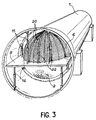
- the height of a table 9 is adjusted so as to support the tubes 6, the overhang of which is excessive given their flexibility.
- the anti-vibration bars 10 are installed above this sheet after having checked that they belong substantially to a plane.
- These bars are held in place using plastic clips 11 made up of two deformable clamps 12 and a connecting body 13 and fixed to the outer tube 6e of the sheet: the clamps 12 grip this tube 6e, and the interval of the clamps 12 allows the anti-vibration bars 10 to be maintained with a small clearance.
- the antivibration bars 10 therefore weigh with a certain distribution of forces on the tubes 6 of the sheet; they are in contact with a certain number of them but have a play with respect to other tubes 6 belonging to this sheet. It is this game that is evaluated using any caliber because all the tubes are easily accessible, which was not the case with the previous process.
- the tubes 6 whose play is too great are considered to be the object of defects. They are therefore removed and replaced by spare tubes, which does not prevent the light expansion which was done before to keep these tubes in place.
- the antivibration bars 10 are now welded together by means of connecting pieces 20 called "pins".
- FIG. 4 which shows their arrangement, represents several tubes 6 belonging to the same ply and whose tube arranged outside the bun is designated by 6th. It also represents the end of a pair of anti-vibration bars 10 from which the clips 11 have been removed.
- the pins 20 are welded at a distance from the outer tube 6e which is defined as a function of the expansion of the tubes 6 which will be carried out subsequently; it is, in practice, necessary to protect the tubes 6 by a thermally insulating cover during welding and which is then removed, and the stiffening action of the pins 20 is completed by straps 22 disposed between them and which oppose the deformation of the assembled half-bun under the action of its own weight.
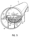
- the straps 22 can be replaced by mechanical holding tools to oppose the deformation of the half-bun.
- the table 9 is dismantled and replaced by a frame 23 to which the straps 22 are attached and which supports the weight of the half-bun using the tie rods 15 which have been kept. We then arrive at the configuration shown in FIG. 5.
- the second half of the bun is then mounted by layers of tubes in the manner described above: installation of anti-vibration bars 10, checking of the clearances, possible replacement of the tubes 6 outside tolerances and installation of a new layer of tubes.
- the antivibration bars 10 of this second half are finally linked together by means of new pins 20.
- the tubes 6 are then correctly positioned and it is possible to expand them on the tube plate 13, after which the assembly of the steam generator is continued according to the prior art.
- the method of mounting tubes by plies which constitutes the invention, has the advantage of being able to control the faults of these tubes, including those which are located inside the bun and which were inaccessible with previous mounting methods.
- the risk of damage following an awkward introduction of the anti-vibration bars is completely eliminated.
- the tubes can be arranged with a much higher density, in particular in staggered, which was not possible with the previous mounting process.
Landscapes
- Engineering & Computer Science (AREA)
- Mechanical Engineering (AREA)
- Physics & Mathematics (AREA)
- Thermal Sciences (AREA)
- General Engineering & Computer Science (AREA)
- Monitoring And Testing Of Nuclear Reactors (AREA)
- Heat-Exchange Devices With Radiators And Conduit Assemblies (AREA)
- Automatic Assembly (AREA)
- Load-Engaging Elements For Cranes (AREA)
- Motor Or Generator Cooling System (AREA)
- Supports For Pipes And Cables (AREA)
Claims (4)
- Verfahren zum Anordnen von Rohren (6) in ebenen Schichten, die voneinander durch dazwischen angeordnete Stangen (10), insbesondere vibrationshemmende Stangen, getrennt sind, in einem Dampferzeuger,
gekennzeichnet durch
die ständige Wiederholung folgender Betriebschrittsequenz, wobei der Dampferzeuger während der Montage so angeordnet ist, daß die Rohrschichten (6) horizontal orientiert sind,- Anordnung einer Schicht von Rohren (6),- Auflegen der Zwischenstangen (10) auf diese Schicht, im Bereich der U-förmigen Krümmungen der Rohre,- Einführen durch Anlegen von Kräften entlang der Zwischenstäbe (10) und senkrecht zur Schichtebene, wobei die Kräfte hinsichtlich ihres Betrages und ihrer Verteilung das Gesamtgewicht simulieren, das die Schichten haben, die auf die schon plazierten Schichten anzuordnen sind,- Überprüfung des Spiels zwischen den Zwischenstäben (10) und jedem der Rohre (6) einer Schicht,- Entfernung der Rohre (6), deren Spiel mit den Zwischenstangen (10) außerhalb der Toleranzen liegt und Ersetzung durch ordnungsgemäße Rohre. - Verfahren nach Anspruch 1, dadurch gekennzeichnet, daß ferner ein Verfahrensschritt zur lösbaren Befestigung der Rohrschichten (6) durch ein leichtes Einwalzen der Rohre (6) erfolgt, sobald diese Schichten plaziert sind.
- Verfahren nach einem der Ansprüche 1 oder 2, dadurch gekennzeichnet, daß die erste Schicht die mittlere Schicht der Rohrverteilung (6) ist und daß zuerst die oberhalb dieser ersten Schicht gelegenen Schichten montiert werden, wonach der Dampferzeuger um eine Halbdrehung gedreht wird derart, daß die montierten Schichten unterhalb die mittlere Schicht gelangen dadurch, daß die Montage der Rohre (6) fortgeführt wird, indem die oberhalb der mittleren Ebene gelegenen Ebenen aufgefüllt werden.
- Verfahren nach Anspruch 3, dadurch gekennzeichnet, daß vor der Drehung des Dampferzeugers ein Verfahrensschritt erfolgt, der darin besteht, daß die Enden der Zwischenstangen (10), die schon plaziert sind, mittels Verbindungsklammern (20) fest miteinander verbunden werden.
Applications Claiming Priority (2)
| Application Number | Priority Date | Filing Date | Title |
|---|---|---|---|
| FR8612126 | 1986-08-27 | ||
| FR8612126A FR2603364B1 (fr) | 1986-08-27 | 1986-08-27 | Procede de placement de tubes dans un generateur de vapeur |
Publications (2)
| Publication Number | Publication Date |
|---|---|
| EP0262011A1 EP0262011A1 (de) | 1988-03-30 |
| EP0262011B1 true EP0262011B1 (de) | 1991-05-15 |
Family
ID=9338532
Family Applications (1)
| Application Number | Title | Priority Date | Filing Date |
|---|---|---|---|
| EP87401930A Expired - Lifetime EP0262011B1 (de) | 1986-08-27 | 1987-08-25 | Verfahren zur Montierung von Rohren in einem Dampferzeuger |
Country Status (10)
| Country | Link |
|---|---|
| US (1) | US4839951A (de) |
| EP (1) | EP0262011B1 (de) |
| JP (1) | JPH0723761B2 (de) |
| KR (1) | KR950007019B1 (de) |
| CN (1) | CN1007999B (de) |
| CA (1) | CA1274676A (de) |
| DE (2) | DE262011T1 (de) |
| ES (1) | ES2002258B3 (de) |
| FR (1) | FR2603364B1 (de) |
| SU (1) | SU1706380A3 (de) |
Families Citing this family (20)
| Publication number | Priority date | Publication date | Assignee | Title |
|---|---|---|---|---|
| US5072786A (en) * | 1990-07-27 | 1991-12-17 | Electric Power Research Institute, Inc. | Anti-vibration support of U-bend flow tubes in a nuclear steam generator |
| FR2684172B1 (fr) * | 1991-11-27 | 1993-12-31 | Framatome | Echangeur de chaleur, a tubes en u equipes d'un dispositif de supportage anti-envol. |
| FR2709174B1 (fr) * | 1993-08-20 | 1995-11-17 | Framatome Sa | Echangeur de chaleur comportant des moyens de maintien de barres antivibratoires intercalés entre les tubes du faisceau de l'échangeur. |
| FR2713971B1 (fr) * | 1993-12-21 | 1996-03-08 | Framatome Sa | Dispositif de maintien provisoire d'une partie d'extrémité d'un faisceau de tubes d'un échangeur de chaleur. |
| FR2714626A1 (fr) * | 1993-12-31 | 1995-07-07 | Framatome Sa | Dispositif de maintien d'un faisceau de tubes d'un échangeur de chaleur pendant la fabrication et le transport de l'échangeur de chaleur. |
| FR2748795B1 (fr) * | 1996-05-15 | 1998-08-28 | Framatome Sa | Dispositif de maintien d'une partie d'extremite d'un faisceau de tubes d'un echangeur de chaleur |
| JP4585414B2 (ja) * | 2005-09-16 | 2010-11-24 | 三菱重工業株式会社 | 振動防止装置およびこれを用いた熱交換器 |
| US8695688B2 (en) * | 2007-07-18 | 2014-04-15 | Babcock & Wilcox Canada Ltd. | Nubbed U-bend tube support |
| JP2012081475A (ja) * | 2010-10-06 | 2012-04-26 | Mitsubishi Heavy Ind Ltd | 異材接合構造 |
| JP5582004B2 (ja) * | 2010-12-07 | 2014-09-03 | 株式会社Ihi | 伝熱管振れ防止バーの固定方法 |
| JP5901266B2 (ja) * | 2011-12-12 | 2016-04-06 | 三菱重工業株式会社 | 蒸気発生器 |
| JP5885949B2 (ja) * | 2011-06-28 | 2016-03-16 | 三菱重工業株式会社 | 蒸気発生器 |
| CN103659169B (zh) * | 2012-09-23 | 2016-06-22 | 丹阳市龙鑫合金有限公司 | 一种制备核电机组的抗振条组件的方法 |
| CN103317245B (zh) * | 2013-06-05 | 2015-08-19 | 上海电气核电设备有限公司 | 一种核电蒸汽发生器穿管和抗震条装焊的方法 |
| US11193715B2 (en) | 2015-10-23 | 2021-12-07 | Hyfra Industriekuhlanlagen Gmbh | Method and system for cooling a fluid with a microchannel evaporator |
| US10619932B2 (en) | 2015-10-23 | 2020-04-14 | Hyfra Industriekuhlanlagen Gmbh | System for cooling a fluid with a microchannel evaporator |
| JP6898200B2 (ja) * | 2017-10-05 | 2021-07-07 | 三菱パワー株式会社 | 熱交換器 |
| US11226139B2 (en) | 2019-04-09 | 2022-01-18 | Hyfra Industriekuhlanlagen Gmbh | Reversible flow evaporator system |
| CN111486740B (zh) * | 2020-04-23 | 2021-09-28 | 中国原子能科学研究院 | 换热器及其组装方法 |
| CN112975268B (zh) * | 2021-05-12 | 2021-08-06 | 上海电气核电设备有限公司 | 一种蒸汽发生器的抗震条的安装方法 |
Citations (1)
| Publication number | Priority date | Publication date | Assignee | Title |
|---|---|---|---|---|
| EP0186957A1 (de) * | 1984-11-13 | 1986-07-09 | Westinghouse Electric Corporation | Schwingungsneutralisierende Stangen für einen Nukleardampferzeuger |
Family Cites Families (8)
| Publication number | Priority date | Publication date | Assignee | Title |
|---|---|---|---|---|
| US3007679A (en) * | 1960-06-22 | 1961-11-07 | Westinghouse Electric Corp | Anti-vibration structure for heat exchanger tubes |
| US3212567A (en) * | 1962-05-08 | 1965-10-19 | Combustion Eng | Anti-vibration support means |
| US4173060A (en) * | 1977-06-24 | 1979-11-06 | Westinghouse Electric Corp. | System and method for retubing a steam generator |
| US4386456A (en) * | 1978-03-31 | 1983-06-07 | Phillips Petroleum Company | Method of assembling a unitary heat exchanger tube bundle assembly |
| US4202085A (en) * | 1978-11-30 | 1980-05-13 | Westinghouse Electric Corp. | Apparatus and method for installing rows of U-shaped tubes in a heat exchanger |
| US4640342A (en) * | 1984-01-26 | 1987-02-03 | Westinghouse Electric Corp. | Expandable antivibration bar for heat transfer tubes of a pressurized water reactor steam generator |
| JPS60245999A (ja) * | 1984-05-21 | 1985-12-05 | Hokkaido Electric Power Co Inc:The | 熱交換器 |
| US4653576A (en) * | 1985-05-01 | 1987-03-31 | Westinghouse Electric Corp. | Expandable antivibration bar for a steam generator |
-
1986
- 1986-08-27 FR FR8612126A patent/FR2603364B1/fr not_active Expired
-
1987
- 1987-08-25 DE DE198787401930T patent/DE262011T1/de active Pending
- 1987-08-25 EP EP87401930A patent/EP0262011B1/de not_active Expired - Lifetime
- 1987-08-25 ES ES87401930T patent/ES2002258B3/es not_active Expired - Lifetime
- 1987-08-25 DE DE8787401930T patent/DE3770100D1/de not_active Expired - Lifetime
- 1987-08-26 CA CA000545427A patent/CA1274676A/en not_active Expired - Lifetime
- 1987-08-26 CN CN87105900A patent/CN1007999B/zh not_active Expired
- 1987-08-26 JP JP62212647A patent/JPH0723761B2/ja not_active Expired - Lifetime
- 1987-08-26 SU SU874203235A patent/SU1706380A3/ru active
- 1987-08-27 US US07/090,059 patent/US4839951A/en not_active Expired - Lifetime
- 1987-08-27 KR KR1019870009369A patent/KR950007019B1/ko not_active Expired - Fee Related
Patent Citations (1)
| Publication number | Priority date | Publication date | Assignee | Title |
|---|---|---|---|---|
| EP0186957A1 (de) * | 1984-11-13 | 1986-07-09 | Westinghouse Electric Corporation | Schwingungsneutralisierende Stangen für einen Nukleardampferzeuger |
Also Published As
| Publication number | Publication date |
|---|---|
| DE262011T1 (de) | 1988-09-01 |
| KR880003140A (ko) | 1988-05-14 |
| JPH0723761B2 (ja) | 1995-03-15 |
| ES2002258A4 (es) | 1988-08-01 |
| US4839951A (en) | 1989-06-20 |
| FR2603364B1 (fr) | 1988-11-10 |
| CA1274676A (en) | 1990-10-02 |
| EP0262011A1 (de) | 1988-03-30 |
| CN87105900A (zh) | 1988-04-13 |
| KR950007019B1 (ko) | 1995-06-26 |
| DE3770100D1 (de) | 1991-06-20 |
| FR2603364A1 (fr) | 1988-03-04 |
| ES2002258B3 (es) | 1992-01-01 |
| CN1007999B (zh) | 1990-05-16 |
| JPS6365202A (ja) | 1988-03-23 |
| SU1706380A3 (ru) | 1992-01-15 |
Similar Documents
| Publication | Publication Date | Title |
|---|---|---|
| EP0262011B1 (de) | Verfahren zur Montierung von Rohren in einem Dampferzeuger | |
| EP0731328B1 (de) | Wärmetauscher mit U-Röhren, mit einer Anti-Auftrieb- und schwingungsneutralisierender Rohrhalterungsvorrichtung | |
| FR2707382A1 (fr) | Echangeur de chaleur comportant un faisceau de tubes cintrés en U et des barres antivibratoires entre les parties cintrées des tubes. | |
| JPH01315602A (ja) | 蒸気タービン翼列を引出すための方法及び装置 | |
| EP0544579B1 (de) | Wärmetauscher mit U-Rohren und Anti-Auftriebshalterung | |
| EP0634607B1 (de) | Dampferzeuger mit abnehmbarem Zyklonabscheidersystem | |
| FR2532224A1 (fr) | Dispositif, bande de retenue et procede pour l'assemblage de grilles de support de barres de combustible nucleaire | |
| EP0145528A1 (de) | Lagergestell für Brennelemente von Kernreaktoren | |
| EP0626536B1 (de) | Dampferzeuger ausgerüstet mit einem Fremdpartikelfilter | |
| EP0088363B1 (de) | Vorrichtung zur Aufhängung von Rohrbündeln | |
| FR2894085A1 (fr) | Armoire electrique comportant un support de cablage. | |
| EP0294273B1 (de) | Metallischer Tragarm | |
| FR2551850A1 (fr) | Procede de construction d'un ensemble cylindrique de rotor pour un echangeur de chaleur regeneratif rotatif | |
| CN103317245B (zh) | 一种核电蒸汽发生器穿管和抗震条装焊的方法 | |
| EP0504039B1 (de) | Verfahren und Vorrichtung zur Herstellung eines ringförmigen Werkstückes aus Blech | |
| EP3479383A1 (de) | Kernreaktor, verfahren für montage und ersatz von thermoelementleitungen, anordnung zur durchführung dieser verfahren | |
| FR2917154A1 (fr) | Procede de demantelement pour la reutilisation des elements de l'enveloppe de pression d'un generateur de vapeur usage d'une centrale nucleaire. | |
| CN211442387U (zh) | 一种钢铁生产用钢材搬运车 | |
| FR2539332A1 (fr) | Machine automatique pour la peinture au pistolet et le sechage d'articles plats, et notamment de panneaux en bois | |
| JPH0638040Y2 (ja) | 電線引出装置 | |
| EP4722474A1 (de) | Mobile servicestation mit einem von einem lastwagen transportierbaren, einteiligen, transportierbaren lufttank, der auf der basis der trägerfundamente des tanks erstreckt | |
| EP0783857B1 (de) | Sprungfedereinheit für Matratzen und Betten, und Verfahren zur Herstellung | |
| FR2505083A1 (fr) | Circuit magnetique de transformateur et procede d'assemblage | |
| JP2021088887A (ja) | シート保持具 | |
| JPH0363042B2 (de) |
Legal Events
| Date | Code | Title | Description |
|---|---|---|---|
| PUAI | Public reference made under article 153(3) epc to a published international application that has entered the european phase |
Free format text: ORIGINAL CODE: 0009012 |
|
| AK | Designated contracting states |
Kind code of ref document: A1 Designated state(s): BE CH DE ES GB IT LI NL |
|
| ITCL | It: translation for ep claims filed |
Representative=s name: JACOBACCI CASETTA & PERANI S.P.A. |
|
| GBC | Gb: translation of claims filed (gb section 78(7)/1977) | ||
| TCNL | Nl: translation of patent claims filed | ||
| DET | De: translation of patent claims | ||
| 17P | Request for examination filed |
Effective date: 19880901 |
|
| 17Q | First examination report despatched |
Effective date: 19900219 |
|
| GRAA | (expected) grant |
Free format text: ORIGINAL CODE: 0009210 |
|
| AK | Designated contracting states |
Kind code of ref document: B1 Designated state(s): BE CH DE ES GB IT LI NL |
|
| REF | Corresponds to: |
Ref document number: 3770100 Country of ref document: DE Date of ref document: 19910620 |
|
| ITF | It: translation for a ep patent filed | ||
| GBT | Gb: translation of ep patent filed (gb section 77(6)(a)/1977) | ||
| REG | Reference to a national code |
Ref country code: ES Ref legal event code: FG2A Ref document number: 2002258 Country of ref document: ES Kind code of ref document: B3 |
|
| PLBE | No opposition filed within time limit |
Free format text: ORIGINAL CODE: 0009261 |
|
| STAA | Information on the status of an ep patent application or granted ep patent |
Free format text: STATUS: NO OPPOSITION FILED WITHIN TIME LIMIT |
|
| 26N | No opposition filed | ||
| PGFP | Annual fee paid to national office [announced via postgrant information from national office to epo] |
Ref country code: NL Payment date: 19960926 Year of fee payment: 10 |
|
| PG25 | Lapsed in a contracting state [announced via postgrant information from national office to epo] |
Ref country code: NL Free format text: LAPSE BECAUSE OF NON-PAYMENT OF DUE FEES Effective date: 19980301 |
|
| NLV4 | Nl: lapsed or anulled due to non-payment of the annual fee |
Effective date: 19980301 |
|
| PGFP | Annual fee paid to national office [announced via postgrant information from national office to epo] |
Ref country code: CH Payment date: 19990805 Year of fee payment: 13 |
|
| PGFP | Annual fee paid to national office [announced via postgrant information from national office to epo] |
Ref country code: ES Payment date: 19990817 Year of fee payment: 13 |
|
| PG25 | Lapsed in a contracting state [announced via postgrant information from national office to epo] |
Ref country code: ES Free format text: LAPSE BECAUSE OF NON-PAYMENT OF DUE FEES Effective date: 20000826 |
|
| PG25 | Lapsed in a contracting state [announced via postgrant information from national office to epo] |
Ref country code: CH Free format text: LAPSE BECAUSE OF NON-PAYMENT OF DUE FEES Effective date: 20000831 Ref country code: LI Free format text: LAPSE BECAUSE OF NON-PAYMENT OF DUE FEES Effective date: 20000831 |
|
| REG | Reference to a national code |
Ref country code: CH Ref legal event code: PL |
|
| REG | Reference to a national code |
Ref country code: GB Ref legal event code: IF02 |
|
| REG | Reference to a national code |
Ref country code: GB Ref legal event code: 732E |
|
| REG | Reference to a national code |
Ref country code: ES Ref legal event code: FD2A Effective date: 20010911 |
|
| PG25 | Lapsed in a contracting state [announced via postgrant information from national office to epo] |
Ref country code: IT Free format text: LAPSE BECAUSE OF NON-PAYMENT OF DUE FEES;WARNING: LAPSES OF ITALIAN PATENTS WITH EFFECTIVE DATE BEFORE 2007 MAY HAVE OCCURRED AT ANY TIME BEFORE 2007. THE CORRECT EFFECTIVE DATE MAY BE DIFFERENT FROM THE ONE RECORDED. Effective date: 20050825 |
|
| PGFP | Annual fee paid to national office [announced via postgrant information from national office to epo] |
Ref country code: GB Payment date: 20060825 Year of fee payment: 20 |
|
| PGFP | Annual fee paid to national office [announced via postgrant information from national office to epo] |
Ref country code: BE Payment date: 20060918 Year of fee payment: 20 |
|
| PGFP | Annual fee paid to national office [announced via postgrant information from national office to epo] |
Ref country code: DE Payment date: 20061002 Year of fee payment: 20 |
|
| REG | Reference to a national code |
Ref country code: GB Ref legal event code: PE20 |
|
| PG25 | Lapsed in a contracting state [announced via postgrant information from national office to epo] |
Ref country code: GB Free format text: LAPSE BECAUSE OF EXPIRATION OF PROTECTION Effective date: 20070824 |
|
| BE20 | Be: patent expired |
Owner name: *FRAMATOME ANP Effective date: 20070825 |