EP0261928B1 - Method and apparatus for the microwave joining of ceramic items - Google Patents
Method and apparatus for the microwave joining of ceramic items Download PDFInfo
- Publication number
- EP0261928B1 EP0261928B1 EP87308375A EP87308375A EP0261928B1 EP 0261928 B1 EP0261928 B1 EP 0261928B1 EP 87308375 A EP87308375 A EP 87308375A EP 87308375 A EP87308375 A EP 87308375A EP 0261928 B1 EP0261928 B1 EP 0261928B1
- Authority
- EP
- European Patent Office
- Prior art keywords
- joint
- items
- ceramic
- microwaves
- measuring
- Prior art date
- Legal status (The legal status is an assumption and is not a legal conclusion. Google has not performed a legal analysis and makes no representation as to the accuracy of the status listed.)
- Expired - Lifetime
Links
- 239000000919 ceramic Substances 0.000 title claims abstract description 37
- 238000000034 method Methods 0.000 title claims description 31
- 238000005304 joining Methods 0.000 title claims description 22
- 239000002184 metal Substances 0.000 claims abstract description 10
- 230000004044 response Effects 0.000 claims abstract description 4
- 230000002269 spontaneous effect Effects 0.000 claims abstract 3
- 230000000638 stimulation Effects 0.000 claims abstract 3
- 230000008859 change Effects 0.000 claims description 3
- 238000005259 measurement Methods 0.000 claims description 3
- 241000269627 Amphiuma means Species 0.000 claims 1
- 230000005855 radiation Effects 0.000 abstract description 11
- 230000015572 biosynthetic process Effects 0.000 abstract description 5
- 238000012544 monitoring process Methods 0.000 abstract description 3
- 239000000523 sample Substances 0.000 description 22
- 239000000463 material Substances 0.000 description 19
- 238000010438 heat treatment Methods 0.000 description 16
- 230000008569 process Effects 0.000 description 11
- 229910010293 ceramic material Inorganic materials 0.000 description 9
- 230000001902 propagating effect Effects 0.000 description 6
- PNEYBMLMFCGWSK-UHFFFAOYSA-N aluminium oxide Inorganic materials [O-2].[O-2].[O-2].[Al+3].[Al+3] PNEYBMLMFCGWSK-UHFFFAOYSA-N 0.000 description 4
- 230000008878 coupling Effects 0.000 description 4
- 238000010168 coupling process Methods 0.000 description 4
- 238000005859 coupling reaction Methods 0.000 description 4
- 238000009792 diffusion process Methods 0.000 description 4
- 230000005684 electric field Effects 0.000 description 4
- 238000009529 body temperature measurement Methods 0.000 description 3
- KZHJGOXRZJKJNY-UHFFFAOYSA-N dioxosilane;oxo(oxoalumanyloxy)alumane Chemical compound O=[Si]=O.O=[Si]=O.O=[Al]O[Al]=O.O=[Al]O[Al]=O.O=[Al]O[Al]=O KZHJGOXRZJKJNY-UHFFFAOYSA-N 0.000 description 3
- 229910052863 mullite Inorganic materials 0.000 description 3
- 229910052581 Si3N4 Inorganic materials 0.000 description 2
- 230000005540 biological transmission Effects 0.000 description 2
- 230000006378 damage Effects 0.000 description 2
- 230000007423 decrease Effects 0.000 description 2
- 230000000694 effects Effects 0.000 description 2
- 238000002474 experimental method Methods 0.000 description 2
- 239000012535 impurity Substances 0.000 description 2
- 230000007246 mechanism Effects 0.000 description 2
- 238000005070 sampling Methods 0.000 description 2
- HQVNEWCFYHHQES-UHFFFAOYSA-N silicon nitride Chemical compound N12[Si]34N5[Si]62N3[Si]51N64 HQVNEWCFYHHQES-UHFFFAOYSA-N 0.000 description 2
- 238000012360 testing method Methods 0.000 description 2
- 238000010521 absorption reaction Methods 0.000 description 1
- 238000006664 bond formation reaction Methods 0.000 description 1
- 238000005219 brazing Methods 0.000 description 1
- 230000006835 compression Effects 0.000 description 1
- 238000007906 compression Methods 0.000 description 1
- 239000004020 conductor Substances 0.000 description 1
- 239000000470 constituent Substances 0.000 description 1
- 238000010411 cooking Methods 0.000 description 1
- 239000007822 coupling agent Substances 0.000 description 1
- 230000002950 deficient Effects 0.000 description 1
- 238000009826 distribution Methods 0.000 description 1
- 238000011156 evaluation Methods 0.000 description 1
- 239000000284 extract Substances 0.000 description 1
- 239000004519 grease Substances 0.000 description 1
- 239000011229 interlayer Substances 0.000 description 1
- 238000010943 off-gassing Methods 0.000 description 1
- 230000003287 optical effect Effects 0.000 description 1
- 238000005457 optimization Methods 0.000 description 1
- 230000000644 propagated effect Effects 0.000 description 1
- 238000003908 quality control method Methods 0.000 description 1
- 230000003068 static effect Effects 0.000 description 1
- 230000003313 weakening effect Effects 0.000 description 1
Images

Classifications
-
- H—ELECTRICITY
- H05—ELECTRIC TECHNIQUES NOT OTHERWISE PROVIDED FOR
- H05B—ELECTRIC HEATING; ELECTRIC LIGHT SOURCES NOT OTHERWISE PROVIDED FOR; CIRCUIT ARRANGEMENTS FOR ELECTRIC LIGHT SOURCES, IN GENERAL
- H05B6/00—Heating by electric, magnetic or electromagnetic fields
- H05B6/64—Heating using microwaves
- H05B6/66—Circuits
- H05B6/68—Circuits for monitoring or control
-
- C—CHEMISTRY; METALLURGY
- C04—CEMENTS; CONCRETE; ARTIFICIAL STONE; CERAMICS; REFRACTORIES
- C04B—LIME, MAGNESIA; SLAG; CEMENTS; COMPOSITIONS THEREOF, e.g. MORTARS, CONCRETE OR LIKE BUILDING MATERIALS; ARTIFICIAL STONE; CERAMICS; REFRACTORIES; TREATMENT OF NATURAL STONE
- C04B35/00—Shaped ceramic products characterised by their composition; Ceramics compositions; Processing powders of inorganic compounds preparatory to the manufacturing of ceramic products
- C04B35/622—Forming processes; Processing powders of inorganic compounds preparatory to the manufacturing of ceramic products
- C04B35/64—Burning or sintering processes
- C04B35/645—Pressure sintering
-
- C—CHEMISTRY; METALLURGY
- C04—CEMENTS; CONCRETE; ARTIFICIAL STONE; CERAMICS; REFRACTORIES
- C04B—LIME, MAGNESIA; SLAG; CEMENTS; COMPOSITIONS THEREOF, e.g. MORTARS, CONCRETE OR LIKE BUILDING MATERIALS; ARTIFICIAL STONE; CERAMICS; REFRACTORIES; TREATMENT OF NATURAL STONE
- C04B37/00—Joining burned ceramic articles with other burned ceramic articles or other articles by heating
- C04B37/001—Joining burned ceramic articles with other burned ceramic articles or other articles by heating directly with other burned ceramic articles
-
- C—CHEMISTRY; METALLURGY
- C04—CEMENTS; CONCRETE; ARTIFICIAL STONE; CERAMICS; REFRACTORIES
- C04B—LIME, MAGNESIA; SLAG; CEMENTS; COMPOSITIONS THEREOF, e.g. MORTARS, CONCRETE OR LIKE BUILDING MATERIALS; ARTIFICIAL STONE; CERAMICS; REFRACTORIES; TREATMENT OF NATURAL STONE
- C04B37/00—Joining burned ceramic articles with other burned ceramic articles or other articles by heating
- C04B37/003—Joining burned ceramic articles with other burned ceramic articles or other articles by heating by means of an interlayer consisting of a combination of materials selected from glass, or ceramic material with metals, metal oxides or metal salts
- C04B37/006—Joining burned ceramic articles with other burned ceramic articles or other articles by heating by means of an interlayer consisting of a combination of materials selected from glass, or ceramic material with metals, metal oxides or metal salts consisting of metals or metal salts
-
- C—CHEMISTRY; METALLURGY
- C04—CEMENTS; CONCRETE; ARTIFICIAL STONE; CERAMICS; REFRACTORIES
- C04B—LIME, MAGNESIA; SLAG; CEMENTS; COMPOSITIONS THEREOF, e.g. MORTARS, CONCRETE OR LIKE BUILDING MATERIALS; ARTIFICIAL STONE; CERAMICS; REFRACTORIES; TREATMENT OF NATURAL STONE
- C04B37/00—Joining burned ceramic articles with other burned ceramic articles or other articles by heating
- C04B37/02—Joining burned ceramic articles with other burned ceramic articles or other articles by heating with metallic articles
- C04B37/023—Joining burned ceramic articles with other burned ceramic articles or other articles by heating with metallic articles characterised by the interlayer used
- C04B37/026—Joining burned ceramic articles with other burned ceramic articles or other articles by heating with metallic articles characterised by the interlayer used consisting of metals or metal salts
-
- C—CHEMISTRY; METALLURGY
- C04—CEMENTS; CONCRETE; ARTIFICIAL STONE; CERAMICS; REFRACTORIES
- C04B—LIME, MAGNESIA; SLAG; CEMENTS; COMPOSITIONS THEREOF, e.g. MORTARS, CONCRETE OR LIKE BUILDING MATERIALS; ARTIFICIAL STONE; CERAMICS; REFRACTORIES; TREATMENT OF NATURAL STONE
- C04B2235/00—Aspects relating to ceramic starting mixtures or sintered ceramic products
- C04B2235/65—Aspects relating to heat treatments of ceramic bodies such as green ceramics or pre-sintered ceramics, e.g. burning, sintering or melting processes
- C04B2235/656—Aspects relating to heat treatments of ceramic bodies such as green ceramics or pre-sintered ceramics, e.g. burning, sintering or melting processes characterised by specific heating conditions during heat treatment
- C04B2235/6562—Heating rate
-
- C—CHEMISTRY; METALLURGY
- C04—CEMENTS; CONCRETE; ARTIFICIAL STONE; CERAMICS; REFRACTORIES
- C04B—LIME, MAGNESIA; SLAG; CEMENTS; COMPOSITIONS THEREOF, e.g. MORTARS, CONCRETE OR LIKE BUILDING MATERIALS; ARTIFICIAL STONE; CERAMICS; REFRACTORIES; TREATMENT OF NATURAL STONE
- C04B2235/00—Aspects relating to ceramic starting mixtures or sintered ceramic products
- C04B2235/65—Aspects relating to heat treatments of ceramic bodies such as green ceramics or pre-sintered ceramics, e.g. burning, sintering or melting processes
- C04B2235/656—Aspects relating to heat treatments of ceramic bodies such as green ceramics or pre-sintered ceramics, e.g. burning, sintering or melting processes characterised by specific heating conditions during heat treatment
- C04B2235/6567—Treatment time
-
- C—CHEMISTRY; METALLURGY
- C04—CEMENTS; CONCRETE; ARTIFICIAL STONE; CERAMICS; REFRACTORIES
- C04B—LIME, MAGNESIA; SLAG; CEMENTS; COMPOSITIONS THEREOF, e.g. MORTARS, CONCRETE OR LIKE BUILDING MATERIALS; ARTIFICIAL STONE; CERAMICS; REFRACTORIES; TREATMENT OF NATURAL STONE
- C04B2235/00—Aspects relating to ceramic starting mixtures or sintered ceramic products
- C04B2235/65—Aspects relating to heat treatments of ceramic bodies such as green ceramics or pre-sintered ceramics, e.g. burning, sintering or melting processes
- C04B2235/66—Specific sintering techniques, e.g. centrifugal sintering
- C04B2235/667—Sintering using wave energy, e.g. microwave sintering
-
- C—CHEMISTRY; METALLURGY
- C04—CEMENTS; CONCRETE; ARTIFICIAL STONE; CERAMICS; REFRACTORIES
- C04B—LIME, MAGNESIA; SLAG; CEMENTS; COMPOSITIONS THEREOF, e.g. MORTARS, CONCRETE OR LIKE BUILDING MATERIALS; ARTIFICIAL STONE; CERAMICS; REFRACTORIES; TREATMENT OF NATURAL STONE
- C04B2237/00—Aspects relating to ceramic laminates or to joining of ceramic articles with other articles by heating
- C04B2237/02—Aspects relating to interlayers, e.g. used to join ceramic articles with other articles by heating
- C04B2237/12—Metallic interlayers
-
- C—CHEMISTRY; METALLURGY
- C04—CEMENTS; CONCRETE; ARTIFICIAL STONE; CERAMICS; REFRACTORIES
- C04B—LIME, MAGNESIA; SLAG; CEMENTS; COMPOSITIONS THEREOF, e.g. MORTARS, CONCRETE OR LIKE BUILDING MATERIALS; ARTIFICIAL STONE; CERAMICS; REFRACTORIES; TREATMENT OF NATURAL STONE
- C04B2237/00—Aspects relating to ceramic laminates or to joining of ceramic articles with other articles by heating
- C04B2237/30—Composition of layers of ceramic laminates or of ceramic or metallic articles to be joined by heating, e.g. Si substrates
- C04B2237/32—Ceramic
- C04B2237/34—Oxidic
- C04B2237/341—Silica or silicates
-
- C—CHEMISTRY; METALLURGY
- C04—CEMENTS; CONCRETE; ARTIFICIAL STONE; CERAMICS; REFRACTORIES
- C04B—LIME, MAGNESIA; SLAG; CEMENTS; COMPOSITIONS THEREOF, e.g. MORTARS, CONCRETE OR LIKE BUILDING MATERIALS; ARTIFICIAL STONE; CERAMICS; REFRACTORIES; TREATMENT OF NATURAL STONE
- C04B2237/00—Aspects relating to ceramic laminates or to joining of ceramic articles with other articles by heating
- C04B2237/30—Composition of layers of ceramic laminates or of ceramic or metallic articles to be joined by heating, e.g. Si substrates
- C04B2237/32—Ceramic
- C04B2237/34—Oxidic
- C04B2237/343—Alumina or aluminates
-
- C—CHEMISTRY; METALLURGY
- C04—CEMENTS; CONCRETE; ARTIFICIAL STONE; CERAMICS; REFRACTORIES
- C04B—LIME, MAGNESIA; SLAG; CEMENTS; COMPOSITIONS THEREOF, e.g. MORTARS, CONCRETE OR LIKE BUILDING MATERIALS; ARTIFICIAL STONE; CERAMICS; REFRACTORIES; TREATMENT OF NATURAL STONE
- C04B2237/00—Aspects relating to ceramic laminates or to joining of ceramic articles with other articles by heating
- C04B2237/30—Composition of layers of ceramic laminates or of ceramic or metallic articles to be joined by heating, e.g. Si substrates
- C04B2237/32—Ceramic
- C04B2237/36—Non-oxidic
- C04B2237/368—Silicon nitride
-
- C—CHEMISTRY; METALLURGY
- C04—CEMENTS; CONCRETE; ARTIFICIAL STONE; CERAMICS; REFRACTORIES
- C04B—LIME, MAGNESIA; SLAG; CEMENTS; COMPOSITIONS THEREOF, e.g. MORTARS, CONCRETE OR LIKE BUILDING MATERIALS; ARTIFICIAL STONE; CERAMICS; REFRACTORIES; TREATMENT OF NATURAL STONE
- C04B2237/00—Aspects relating to ceramic laminates or to joining of ceramic articles with other articles by heating
- C04B2237/30—Composition of layers of ceramic laminates or of ceramic or metallic articles to be joined by heating, e.g. Si substrates
- C04B2237/40—Metallic
-
- C—CHEMISTRY; METALLURGY
- C04—CEMENTS; CONCRETE; ARTIFICIAL STONE; CERAMICS; REFRACTORIES
- C04B—LIME, MAGNESIA; SLAG; CEMENTS; COMPOSITIONS THEREOF, e.g. MORTARS, CONCRETE OR LIKE BUILDING MATERIALS; ARTIFICIAL STONE; CERAMICS; REFRACTORIES; TREATMENT OF NATURAL STONE
- C04B2237/00—Aspects relating to ceramic laminates or to joining of ceramic articles with other articles by heating
- C04B2237/50—Processing aspects relating to ceramic laminates or to the joining of ceramic articles with other articles by heating
- C04B2237/72—Forming laminates or joined articles comprising at least two interlayers directly next to each other
-
- C—CHEMISTRY; METALLURGY
- C04—CEMENTS; CONCRETE; ARTIFICIAL STONE; CERAMICS; REFRACTORIES
- C04B—LIME, MAGNESIA; SLAG; CEMENTS; COMPOSITIONS THEREOF, e.g. MORTARS, CONCRETE OR LIKE BUILDING MATERIALS; ARTIFICIAL STONE; CERAMICS; REFRACTORIES; TREATMENT OF NATURAL STONE
- C04B2237/00—Aspects relating to ceramic laminates or to joining of ceramic articles with other articles by heating
- C04B2237/50—Processing aspects relating to ceramic laminates or to the joining of ceramic articles with other articles by heating
- C04B2237/78—Side-way connecting, e.g. connecting two plates through their sides
-
- Y—GENERAL TAGGING OF NEW TECHNOLOGICAL DEVELOPMENTS; GENERAL TAGGING OF CROSS-SECTIONAL TECHNOLOGIES SPANNING OVER SEVERAL SECTIONS OF THE IPC; TECHNICAL SUBJECTS COVERED BY FORMER USPC CROSS-REFERENCE ART COLLECTIONS [XRACs] AND DIGESTS
- Y02—TECHNOLOGIES OR APPLICATIONS FOR MITIGATION OR ADAPTATION AGAINST CLIMATE CHANGE
- Y02B—CLIMATE CHANGE MITIGATION TECHNOLOGIES RELATED TO BUILDINGS, e.g. HOUSING, HOUSE APPLIANCES OR RELATED END-USER APPLICATIONS
- Y02B40/00—Technologies aiming at improving the efficiency of home appliances, e.g. induction cooking or efficient technologies for refrigerators, freezers or dish washers
Definitions
- the invention relates to a method and apparatus for the microwave joining of two materials, particularly ceramic items.
- the bonding together of ceramic materials is generally accomplished by many different methods and apparatuses. Exemplary methods and apparatuses are shown and described in U.S. Patent Nos. 4,384,909, 4,347,089, 3,998,632, 3,841,870, and 3,755,065.
- Prior art apparatuses for making joints between ceramic materials by using microwave energy have sometimes employed ovens conventionally used for cooking food.
- the microwave field exists in many different orientations and the power supplied to the oven is distributed accordingly. Not all of these orientations or modes couple efficiently to the ceramic items being joined.
- no methods and apparatuses in the prior art are known to simultaneously apply compressive forces to the ceramic items in order to stimulate and enhance the joining together of such items and to monitor continuously the joint being formed between the two ceramic items in order to assure a good bond.
- EP-A-0251256 (Published 7th January 1988 in pursuance of European Patent Application No. 87109251.6 filed 26th June 1987 and claiming the priority date of 30th June 1986) discloses the microwave joining of ceramics by radiating microwaves onto a joint located in a cavity resonator. The joining surfaces are pressed together and the temperature distribution of the ceramics is controlled so that the temperature is highest at the joining surfaces and decreases towards their unjoined ends.
- the temperature control is an essential feature and there is no disclosure of nondestructively evaluating the joint.
- the primary object of the present invention is to use the more rapid and substantially uniform heating possible with microwave energy to join ceramic materials in order to obtain improved strength and reliability as compared to materials bonded by conventional heating methods and apparatuses.
- microwave heating derive from the fact that heat is produced internally in the material being joined through dissipation of the electromagnetic energy absorbed by molecular dipoles in the material.
- microwave-heated specimens show a residual temperature gradient that is the reverse of the usual gradient observed with conventional heating methods, i.e. the center is hotter than the outer surface.
- microwave energy to heat materials has three distinct advantages: substantially uniform heating, more rapid heating, and a reversed temperature gradient. These advantages enhance the properties of microwave-treated ceramic materials in several ways.
- the substantial uniformity of heating tends to minimize the buildup of residual stresses, and, additionally, inhibits the diffusion of impurities throughout the material.
- the more rapid heating prevents grain growth and the weakening usually associated with the longer heating times of conventional thermal joining processes.
- the reversed thermal gradient enhances the outgassing of impurities from the center to the outer surface of the material and is a new mechanism for controlled constituent diffusion.
- the present invention has three additional advantages not found in the prior art methods and apparatuses for the microwave joining of ceramic material.
- a single mode microwave applicator is used so that the microwave field can be oriented to optimize the coupling of the radiation to the joint being formed, thereby increasing energy efficiency.
- a compressive force is simultaneously applied to the ceramic items being joined so that the microwave joining process is essentially completed in a much shorter time than in a conventional heat- joining process.
- the joint being formed is continuously monitored by a nondestructive evaluator to assure that a good continuous bond is formed.
- each bond has sufficient structural integrity because it uses a nondestructive evaluator to monitor constantly each bond during its formation.
- the present invention is basically more efficient than the prior art convection and microwave ovens in which the entire mass of material inside the oven is heated. These conventional microwave ovens are energy- inefficient because mixed modes are used instead of only a single mode.
- Compressive forces are easily applied to the ceramic items because only the region to be joined together is exposed to the microwave radiation while the rest of the ceramic material is outside of the single-mode microwave applicator. To the parts of the ceramic items outside of the applicator, a compressive force is applied, thereby speeding up the joining process.
- a nondestructive evaluator can be attached directly to the ceramic items. For example, in this way, acoustic reflections from the joint region can be monitored and the quality of the joint being formed can be continuously assessed.
- the joint or bond produced by the method and apparatus of the present invention is as strong as or stronger than the virgin ceramic material. Furthermore, no braze is required although brazing material may be used and is not precluded from use by the present invention.
- FIG. 1 the apparatus for joining two ceramic items together by applying microwave energy is shown.
- a magnetron 11 generates a microwave signal and delivers up to 1,000 watts of power at a frequency of about 2.45 gigahertz (GHz) in the direction of the arrow which represents a waveguide.
- GHz gigahertz
- a first circulator 12 directs the microwave energy in sequence along the path defined by the arrows and acts as a one way gate or isolator to protect the magnetron 11 against reflected microwaves. Any reflected microwaves are directed by this first circulator 12 to a first resistive load element 39 where they are dissipated.
- a voltage sampling probe 14 senses the magnitude of the propagating voltage of the microwave and extracts a very small fraction of it.
- a power head 15 receives this small part of the propagating voltage and provides an output voltage proportional to the square of the input voltage.
- a power meter 16 is used in conjunction with the power head 15 to provide an output display and voltage proportional to the forward propagating microwave voltage. This output then is fed into a noninverting input of a differential amplifier 22.
- the remaining part of the forward propagating voltage is transmitted to a second circulator 17 which acts as a microwave bridge element.
- This second circulator 17 has two functions represented by the double-headed arrow on the right-hand side thereof.
- the circulator 17 allows microwaves to pass in the forward direction to a chamber 21.
- the circulator 17 redirects power reflected from the chamber 21 to a voltage sampling probe 24, a power head 25, a power meter 26, and to an inverting input of the differential amplifier 22. Any excess reflected microwaves are directed by the second circulator 17 to a second resistive load element 40 where they are dissipated.
- the probe 24, power head 25, and power meter 26 are devices identical to the probe 14, power head 15, and power meter 16. However, the probe 24 senses the magnitude of reflected voltage and the power meter 26 provides an output display and voltage proportional to the reflected power, whereas the probe 14 and the power meter 16 deal only with forward power.
- the forward propagating voltage is fed into the chamber 21 through an adjustable iris 23 which focuses the microwave energy onto a joint J to be formed between two materials.
- the materials are two ceramic items or samples S 1 and S 2 .
- the chamber 21 has an internal microwave resonant cavity 27 which is adjustable in size by moving a Slidable rear wall 28 forwardly and backwardly with a handle 29. Moving the handle 29 allows an operator to adjust the position of the rear wall 28 so that the length of the cavity 27 in the chamber 21 is changed. This change allows a change in the resonant frequency of the cavity 27 which, in turn, makes possible a standing microwave field inside the cavity 27 between the iris 23 and the Slidable rear wall 28.
- the rear wall 28 may be fixed, thus giving rise to a predetermined resonant frequency in the cavity.
- a microwave source of variable frequency must be used.
- a compressor 30 is an hydraulic ram which is located at one end of the ceramic sample S 1 which protrudes outside of the chamber 21.
- the compressor 30 applies a force across the samples S 1 and S 2 .
- a load cell 31 measures the static force applied to one end of the sample S 1 by the compressor 30.
- the samples S 1 and S 2 may be any suitable ceramic such as alumina (AI203), mullite (Si 2 Al 6 O 13 ) or silicon nitride (Si 3 N 4 ).
- alumina AI203
- mullite Si 2 Al 6 O 13
- silicon nitride Si 3 N 4
- Experimental data taken in the laboratory took into account both the dielectric properties of these specific ceramic materials and the radiation of heat from the outer surface of each sample S 1 and S 2 .
- Initial heating rates for joining the oxide material samples were 20 ° C per second typically, and were tested to 100 ° C per second when exposed to the microwave radiation.
- the radial temperature profile for a 3/8 in (1 cm) diameter rod for samples S 1 and S 2 made of alumina was calculated to have a temperature difference of 2% between the center and the exterior surface with the center being hotter and, therefore, still maintaining a substantially uniform heating profile.
- a nondestructive evaluator 32 is positioned at the lower end of the sample S 2 and constantly monitors acoustic pulses reflected from the region of the joint being formed inside the cavity 27. As long as there is a space or an air gap at the joint J, acoustic pulses sent from the evaluator 32 along the sample S 2 will be reflected at this gap and sent back to the evaluator 32.
- the acoustic pulses from the evaluator 32 will pass from the sample S 2 along the longitudinal axis of the sample S 1 , thus reducing the reflected acoustic pulses to zero magnitude and indicating that a bond is formed between the samples S 1 and S 2 .
- Fig. 1 it may be seen that, from the infrared pyrometer 19, the temperature measurements of the sample S 2 at the joint J are fed electronically to a free running two-channel strip chart recorder 18.
- the power which is applied to the joint J is the same in magnitude as the forward power minus the reflected power. Since a voltage proportional to the forward power is presented to the noninverting input of the differential amplifier 22, and a voltage proportional to the power reflected at the iris 23 is presented to the inverting input of the differential amplifier 22, the output voltage of the differential amplifier 22 is proportional to the microwave power in the cavity 27 inside the chamber 21.
- This power is the power available to be absorbed by the samples S 1 and S 2 at the joint J during formation of a bond thereat.
- the output of the differential amplifier 22, representing the available power for absorption, is fed into the recorder 18 and is graphed against time marked by the recorder 18 and also against temperature measurements taken at the joint J by the pyrometer 19.
- the output of the recorder 18 is a strip chart which graphs absorbed power and measured temperature versus elapsed time.
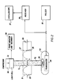
- the details of the compressor 30 and the nondestructive evaluator 32 are shown.
- the resonant frequency of the cavity 27 inside chamber 21 is adjusted by moving a slidable rear wall 28 with a handle 29 until a standing microwave field is established with a maximum amplitude of the electric field component at the joint J between samples S 1 and S 2 .
- an acoustic coupling agent e.g. grease
- an acoustic magnifying lens 33 which maximizes the acoustic signal transferred to and from the sample S 2 to and from a transducer 34.
- the transducer 34 converts electric pulses received from a transmitter or pulser 35 into acoustic pulses and sends these acoustic pulses up sample S 2 to the joint J from which the acoustic pulses are reflected back through sample S 2 to the acoustic magnifying lens 33 and the transducer 34. On the return trip, the transducer 34 converts the acoustic pulses back into electric pulses which are sent to a receiver 36. The output of the receiver 36 then is displayed on an oscilloscope 37.
- the compressor 30 and the evaluator 32 are both arranged outside of the chamber 21 which holds the microwaved samples S 1 and S 2 about which measurements are taken accurately without heat and radiation damage to the measuring instruments.
- the elements described above constitute the components of the apparatus for the microwave joining of materials, such as ceramics.
- the process may be explained as follows by referring again to Fig. 1.
- the microwave energy propagates from the generating magnetron 11 along a waveguide schematically shown by the arrows to the chamber 21.
- the standing wave of the microwave field has maximum amplitude at three nearly equally spaced positions.
- the ceramic samples S 1 and S 2 are located so that they may absorb and dissipate as heat nearly all of the available microwave power.
- the iris 23 which allows the microwave energy to enter the chamber 21, acts as a variable impedance transformer and matches the impedance of the cavity 27 to the impedance of the rectangular waveguide which leads the microwaves up to the chamber 21.
- Variable coupling is achieved by adjusting the opening of the iris 23 so as to control the degree of coupling.
- the reason for using a chamber 21 with a cavity 27 which is adjustable in length by a Slidable rear wall 28 is that, as opposed to a terminated waveguide section, the power in the cavity 27 is Q times the power in the propagating microwave field where Q is the quality factor of the cavity 27 defined as the ratio of (2 1T f) x (average energy stored per cycle) to the power lost. Therefore, since Q may be several thousand units, the cavity 27 requires very little incident power to achieve a high level of stored energy and so a high level of energy is available to be dissipated by the samples S 1 and S 2 . Of course, the energy dissipated can never exceed that associated with the microwave being propagated outside the cavity 27.
- thermocouple or thermistor cannot be inserted into the cavity 27 to measure the temperature of the samples S 1 and S 2 because any conducting material introduced therein will behave as an antenna or a section of a coaxial transmission line which could conduct the microwaves outside of the cavity 27.
- this phenomenon is the principle upon which the voltage coupling probes 14 and 24 are based.
- the noninvasive temperature measuring technique of the present invention is used, i.e. measuring the intensity of the infrared radiation emitted from the outer surface of the heated sample S 2 . This intensity is uniquely related, through Planck's radiation law, to the temperature at the surface of the material. Unfortunately, this relationship also depends on the emissivity of the surface.
- This emissivity is a measure of the radiative effectiveness of the surface such that, for a perfectly black surface, all radiation is either emitted or absorbed while, for a perfectly white surface, no radiation is either emitted or absorbed, i.e. it is all reflected internally or externally, respectively.
- the present invention employs a so-called "two-color" pyrometer 19 which causes such errors to be cancelled.
- microwaves were supplied by magnetron 11 and were transmitted through the rectangular waveguide schematically shown by the arrows to the chamber 21 having the cavity 27 in which the samples S 1 and S 2 were arranged.
- the cavity 27 supported a single mode microwave field configuration and had a resonant frequency which was varied by adjusting the rear wall 28 after the microwave field entered the cavity 27 through the iris 23.
- the power absorbed by the samples S 1 and S 2 was measured as the difference between the forward power focused into the cavity 27 and the power reflected back out of the cavity 27.
- the samples S 1 and S 2 were placed at the maximum electric field amplitude of the standing microwave.
- the compressor 30, located outside the chamber 21, provided force to the samples S 1 and S 2 during the joining process.
- a load cell 31 measures the force and transmits its data to a force monitor and recorder 38 which displays the data for the operator. While fabricating the bond, the power absorbed, the temperature reached, and the pressure applied are monitored and recorded appropriately on the recorder 18 of Fig. 1 and the recorder 38 of Fig. 2 as a function of time. These measurements were made to be sure that optimization of the power, temperature, and compression, each as a function of time, occurred during the joining process.
- joints as well as joints made between alumina samples were thermal diffusion bonds.
- the present invention is also capable of handling brazed ceramic to ceramic joints
- the conventional braze joint for ceramic to metal joints, there are two different types of joints possible, namely the conventional braze joint and an indirect braze joint using an interlayer.
- the position of the metal rod or other type of nonceramic specimen must first be carefully adjusted so that the end to be joined to the ceramic rod or specimen coincides with and becomes a part of an interior wall of the cavity 27 inside the chamber 21.
- the metal rod can then be inserted slightly through the top or bottom openings in the chamber 21.
- the metal rod inserted into the cavity 27 essentially serves as a capacitive post, and the electrical reactance of this post as well as its effect on the heating process can be computed with a high degree of accuracy.
- the ceramic specimen can then be brought into contact with the metal specimen and heated in exactly the same manner as in the ceramic to ceramic bonding process because the bond will still be formed at the maximum electric field position of the cavity 27 which will have been retuned for the metal to ceramic joining process. Note that the electric field is constant along the longitudinal axis of the cylindrical samples S 1 and S 2 . Also, calculations of the temperature/time profile for a metal to ceramic joining process can still be made.
Landscapes
- Chemical & Material Sciences (AREA)
- Engineering & Computer Science (AREA)
- Ceramic Engineering (AREA)
- Materials Engineering (AREA)
- Structural Engineering (AREA)
- Organic Chemistry (AREA)
- Manufacturing & Machinery (AREA)
- Physics & Mathematics (AREA)
- Electromagnetism (AREA)
- Inorganic Chemistry (AREA)
- Ceramic Products (AREA)
- Physical Or Chemical Processes And Apparatus (AREA)
Applications Claiming Priority (2)
| Application Number | Priority Date | Filing Date | Title |
|---|---|---|---|
| US06/910,984 US4767902A (en) | 1986-09-24 | 1986-09-24 | Method and apparatus for the microwave joining of ceramic items |
| US910984 | 1986-09-24 |
Publications (3)
| Publication Number | Publication Date |
|---|---|
| EP0261928A2 EP0261928A2 (en) | 1988-03-30 |
| EP0261928A3 EP0261928A3 (en) | 1989-10-04 |
| EP0261928B1 true EP0261928B1 (en) | 1992-03-11 |
Family
ID=25429609
Family Applications (1)
| Application Number | Title | Priority Date | Filing Date |
|---|---|---|---|
| EP87308375A Expired - Lifetime EP0261928B1 (en) | 1986-09-24 | 1987-09-22 | Method and apparatus for the microwave joining of ceramic items |
Country Status (5)
| Country | Link |
|---|---|
| US (1) | US4767902A (enExample) |
| EP (1) | EP0261928B1 (enExample) |
| JP (1) | JPS6389473A (enExample) |
| CA (1) | CA1297166C (enExample) |
| DE (1) | DE3777301D1 (enExample) |
Families Citing this family (20)
| Publication number | Priority date | Publication date | Assignee | Title |
|---|---|---|---|---|
| US4757172A (en) * | 1986-09-24 | 1988-07-12 | Questech Inc. | Method and apparatus for the microwave joining of nonoxide ceramic items |
| US5164130A (en) * | 1990-04-20 | 1992-11-17 | Martin Marietta Energy Systems, Inc. | Method of sintering ceramic materials |
| US5154779A (en) * | 1990-04-20 | 1992-10-13 | Martin Marietta Energy Systems, Inc. | Method of nitriding, carburizing, or oxidizing refractory metal articles using microwaves |
| JPH05506066A (ja) * | 1990-04-20 | 1993-09-02 | マーチン・マリエッタ・エナジー・システムズ・インク | 耐熱性金属物品の窒化方法 |
| US5241040A (en) * | 1990-07-11 | 1993-08-31 | International Business Machines Corporation | Microwave processing |
| US5191182A (en) * | 1990-07-11 | 1993-03-02 | International Business Machines Corporation | Tuneable apparatus for microwave processing |
| US5648038A (en) * | 1995-09-20 | 1997-07-15 | Lambda Technologies | Systems and methods for monitoring material properties using microwave energy |
| US6054700A (en) * | 1997-04-10 | 2000-04-25 | Nucon Systems | Process and apparatus for joining thick-walled ceramic parts |
| US6644536B2 (en) * | 2001-12-28 | 2003-11-11 | Intel Corporation | Solder reflow with microwave energy |
| US7560657B2 (en) | 2002-05-08 | 2009-07-14 | Btu International Inc. | Plasma-assisted processing in a manufacturing line |
| US7498066B2 (en) | 2002-05-08 | 2009-03-03 | Btu International Inc. | Plasma-assisted enhanced coating |
| WO2003095130A1 (en) | 2002-05-08 | 2003-11-20 | Dana Corporation | Plasma-assisted sintering |
| US7465362B2 (en) | 2002-05-08 | 2008-12-16 | Btu International, Inc. | Plasma-assisted nitrogen surface-treatment |
| US7445817B2 (en) | 2002-05-08 | 2008-11-04 | Btu International Inc. | Plasma-assisted formation of carbon structures |
| US7497922B2 (en) | 2002-05-08 | 2009-03-03 | Btu International, Inc. | Plasma-assisted gas production |
| US7494904B2 (en) | 2002-05-08 | 2009-02-24 | Btu International, Inc. | Plasma-assisted doping |
| US7638727B2 (en) | 2002-05-08 | 2009-12-29 | Btu International Inc. | Plasma-assisted heat treatment |
| US7432470B2 (en) | 2002-05-08 | 2008-10-07 | Btu International, Inc. | Surface cleaning and sterilization |
| US7189940B2 (en) | 2002-12-04 | 2007-03-13 | Btu International Inc. | Plasma-assisted melting |
| US7022198B2 (en) * | 2003-03-07 | 2006-04-04 | The United States Of America As Represented By The Secretary Of The Navy | Microwave assisted reactive brazing of ceramic materials |
Family Cites Families (19)
| Publication number | Priority date | Publication date | Assignee | Title |
|---|---|---|---|---|
| US3469053A (en) * | 1965-10-19 | 1969-09-23 | Melvin L Levinson | Microwave kiln |
| US3520055A (en) * | 1967-04-26 | 1970-07-14 | Western Electric Co | Method for holding workpieces for radiant energy bonding |
| FR2079945A5 (enExample) * | 1970-02-18 | 1971-11-12 | Materiel Telephonique | |
| US3755065A (en) * | 1971-05-11 | 1973-08-28 | Owens Illinois Inc | Oxidic solder sealing compositions and their use in forming laminates |
| US3998632A (en) * | 1972-04-27 | 1976-12-21 | Valentin Petrovich Kosteruk | Metal alloy |
| US3841870A (en) * | 1973-03-07 | 1974-10-15 | Carpenter Technology Corp | Method of making articles from powdered material requiring forming at high temperature |
| US4003368A (en) * | 1974-06-27 | 1977-01-18 | Armco Steel Corporation | Article transparent to microwaves and process for making same |
| US3953703A (en) * | 1974-10-03 | 1976-04-27 | Materials Research Corporation | Method for drying ceramic tape |
| JPS5823349B2 (ja) * | 1975-08-11 | 1983-05-14 | 新日本製鐵株式会社 | タイカブツノシヨウケツホウホウ |
| US4179596A (en) * | 1978-04-27 | 1979-12-18 | Litton Systems, Inc. | Method for processing fiberoptic electronic components of electronic vacuum devices |
| US4219361A (en) * | 1978-06-09 | 1980-08-26 | Special Metals Corporation | Method of improving the susceptibility of a material to microwave energy heating |
| US4307277A (en) * | 1978-08-03 | 1981-12-22 | Mitsubishi Denki Kabushiki Kaisha | Microwave heating oven |
| US4273950A (en) * | 1979-05-29 | 1981-06-16 | Photowatt International, Inc. | Solar cell and fabrication thereof using microwaves |
| US4292262A (en) * | 1979-06-28 | 1981-09-29 | Tobin Jr Leo W | Ceramic material processing |
| US4347089A (en) * | 1981-07-29 | 1982-08-31 | Sri International | Method for bonding silicon nitride |
| US4384909A (en) * | 1981-11-16 | 1983-05-24 | United Technologies Corporation | Bonding Si3 N4 ceramics |
| US4529856A (en) * | 1983-10-04 | 1985-07-16 | The United States Of America As Represented By The United States Department Of Energy | Ceramic-glass-metal seal by microwave heating |
| US4529857A (en) * | 1983-10-04 | 1985-07-16 | The United States Of America As Represented By The United States Department Of Energy | Ceramic-glass-ceramic seal by microwave heating |
| JPS6311580A (ja) * | 1986-06-30 | 1988-01-19 | 株式会社豊田中央研究所 | セラミツクスの接合装置 |
-
1986
- 1986-09-24 US US06/910,984 patent/US4767902A/en not_active Expired - Fee Related
-
1987
- 1987-09-21 CA CA000547437A patent/CA1297166C/en not_active Expired - Lifetime
- 1987-09-22 EP EP87308375A patent/EP0261928B1/en not_active Expired - Lifetime
- 1987-09-22 DE DE8787308375T patent/DE3777301D1/de not_active Expired - Fee Related
- 1987-09-24 JP JP62239889A patent/JPS6389473A/ja active Granted
Also Published As
| Publication number | Publication date |
|---|---|
| EP0261928A3 (en) | 1989-10-04 |
| DE3777301D1 (de) | 1992-04-16 |
| EP0261928A2 (en) | 1988-03-30 |
| US4767902A (en) | 1988-08-30 |
| CA1297166C (en) | 1992-03-10 |
| JPH0367984B2 (enExample) | 1991-10-24 |
| JPS6389473A (ja) | 1988-04-20 |
Similar Documents
| Publication | Publication Date | Title |
|---|---|---|
| EP0261928B1 (en) | Method and apparatus for the microwave joining of ceramic items | |
| EP0308593B1 (en) | Method and apparatus for the microwave joining of nonoxide ceramic items | |
| Favro et al. | Infrared imaging of defects heated by a sonic pulse | |
| Eyerer | Thermal wave remote and nondestructive inspection of polymers. | |
| Hartley et al. | Measurement of the temperature profile during shear band formation in steels deforming at high strain rates | |
| Balasubramaniam et al. | High temperature ultrasonic sensor for the simultaneous measurement of viscosity and temperature of melts | |
| US7716987B2 (en) | Non-contact thermo-elastic property measurement and imaging system for quantitative nondestructive evaluation of materials | |
| US5469742A (en) | Acoustic temperature and film thickness monitor and method | |
| JP2001242110A (ja) | 圧電セラミック素子の検査方法 | |
| Partouche-Sebban et al. | An investigation of shock induced temperature rise and melting of bismuth using high-speed optical pyrometry | |
| CN111157617B (zh) | 一种测量固体材料温度相关杨氏模量的系统及方法 | |
| Palaith et al. | Microwave joining of ceramics | |
| Tittmann et al. | Ultrasonic sensors for high temperature applications | |
| JPH0318745A (ja) | 超高温物質の電磁特性測定用装置 | |
| US5374122A (en) | Method for quantifying porosity of parts of simple and complex geometries | |
| EP0165213B1 (en) | Process and device for the non-destructive test of a joint between sheets made by electric spot welding | |
| Yarlagadda et al. | Characterisation of materials behaviour in microwave joining of ceramics | |
| Ihara et al. | Materials evaluation using long clad buffer rods | |
| JPH0518833A (ja) | 残留応力測定方法およびそれに用いるレンズ | |
| JPH08313497A (ja) | 接合装置 | |
| Siu et al. | Variable Frequency Microwaves (VFM) for Non-Destructive Testing and Evaluation of Adhesively Bonded Polymers | |
| MacLachlan et al. | Characterization of ceramic coatings by advanced nondestructive evaluation methods | |
| JPH02231547A (ja) | セラミックスコーティング製品の耐熱性検査方法 | |
| Gondard et al. | Three ultrasonic devices for the elastic moduli determination at high temperatures | |
| Boyd | Pulsed EMAT (Electromagnetic Acoustic Transducer) acoustic measurements on a horizontal continuous caster for internal temperature determination |
Legal Events
| Date | Code | Title | Description |
|---|---|---|---|
| PUAI | Public reference made under article 153(3) epc to a published international application that has entered the european phase |
Free format text: ORIGINAL CODE: 0009012 |
|
| AK | Designated contracting states |
Kind code of ref document: A2 Designated state(s): DE FR GB IT SE |
|
| RAP1 | Party data changed (applicant data changed or rights of an application transferred) |
Owner name: QUESTECH INC. |
|
| PUAL | Search report despatched |
Free format text: ORIGINAL CODE: 0009013 |
|
| AK | Designated contracting states |
Kind code of ref document: A3 Designated state(s): DE FR GB IT SE |
|
| 17P | Request for examination filed |
Effective date: 19900403 |
|
| RAP3 | Party data changed (applicant data changed or rights of an application transferred) |
Owner name: QUESTECH INC. |
|
| 17Q | First examination report despatched |
Effective date: 19910314 |
|
| GRAA | (expected) grant |
Free format text: ORIGINAL CODE: 0009210 |
|
| AK | Designated contracting states |
Kind code of ref document: B1 Designated state(s): DE FR GB IT SE |
|
| ITF | It: translation for a ep patent filed | ||
| REF | Corresponds to: |
Ref document number: 3777301 Country of ref document: DE Date of ref document: 19920416 |
|
| ET | Fr: translation filed | ||
| PLBE | No opposition filed within time limit |
Free format text: ORIGINAL CODE: 0009261 |
|
| STAA | Information on the status of an ep patent application or granted ep patent |
Free format text: STATUS: NO OPPOSITION FILED WITHIN TIME LIMIT |
|
| 26N | No opposition filed | ||
| EAL | Se: european patent in force in sweden |
Ref document number: 87308375.2 |
|
| PGFP | Annual fee paid to national office [announced via postgrant information from national office to epo] |
Ref country code: SE Payment date: 19950831 Year of fee payment: 9 |
|
| PG25 | Lapsed in a contracting state [announced via postgrant information from national office to epo] |
Ref country code: SE Effective date: 19960923 |
|
| REG | Reference to a national code |
Ref country code: FR Ref legal event code: D6 |
|
| PGFP | Annual fee paid to national office [announced via postgrant information from national office to epo] |
Ref country code: DE Payment date: 19970113 Year of fee payment: 10 |
|
| EUG | Se: european patent has lapsed |
Ref document number: 87308375.2 |
|
| PGFP | Annual fee paid to national office [announced via postgrant information from national office to epo] |
Ref country code: GB Payment date: 19970916 Year of fee payment: 11 |
|
| PGFP | Annual fee paid to national office [announced via postgrant information from national office to epo] |
Ref country code: FR Payment date: 19970930 Year of fee payment: 11 |
|
| PG25 | Lapsed in a contracting state [announced via postgrant information from national office to epo] |
Ref country code: DE Free format text: LAPSE BECAUSE OF NON-PAYMENT OF DUE FEES Effective date: 19980603 |
|
| PG25 | Lapsed in a contracting state [announced via postgrant information from national office to epo] |
Ref country code: GB Free format text: LAPSE BECAUSE OF NON-PAYMENT OF DUE FEES Effective date: 19980922 |
|
| GBPC | Gb: european patent ceased through non-payment of renewal fee |
Effective date: 19980922 |
|
| PG25 | Lapsed in a contracting state [announced via postgrant information from national office to epo] |
Ref country code: FR Free format text: LAPSE BECAUSE OF NON-PAYMENT OF DUE FEES Effective date: 19990531 |
|
| REG | Reference to a national code |
Ref country code: FR Ref legal event code: ST |
|
| PG25 | Lapsed in a contracting state [announced via postgrant information from national office to epo] |
Ref country code: IT Free format text: LAPSE BECAUSE OF NON-PAYMENT OF DUE FEES;WARNING: LAPSES OF ITALIAN PATENTS WITH EFFECTIVE DATE BEFORE 2007 MAY HAVE OCCURRED AT ANY TIME BEFORE 2007. THE CORRECT EFFECTIVE DATE MAY BE DIFFERENT FROM THE ONE RECORDED. Effective date: 20050922 |