EP0261272B1 - Air-driven dental scaler - Google Patents
Air-driven dental scaler Download PDFInfo
- Publication number
- EP0261272B1 EP0261272B1 EP86113258A EP86113258A EP0261272B1 EP 0261272 B1 EP0261272 B1 EP 0261272B1 EP 86113258 A EP86113258 A EP 86113258A EP 86113258 A EP86113258 A EP 86113258A EP 0261272 B1 EP0261272 B1 EP 0261272B1
- Authority
- EP
- European Patent Office
- Prior art keywords
- casing
- chamber
- scaler
- vibrator
- air
- Prior art date
- Legal status (The legal status is an assumption and is not a legal conclusion. Google has not performed a legal analysis and makes no representation as to the accuracy of the status listed.)
- Expired
Links
- 230000004323 axial length Effects 0.000 claims description 5
- 238000007599 discharging Methods 0.000 claims 3
- YUBJPYNSGLJZPQ-UHFFFAOYSA-N Dithiopyr Chemical compound CSC(=O)C1=C(C(F)F)N=C(C(F)(F)F)C(C(=O)SC)=C1CC(C)C YUBJPYNSGLJZPQ-UHFFFAOYSA-N 0.000 claims 2
- 208000036366 Sensation of pressure Diseases 0.000 claims 2
- XLYOFNOQVPJJNP-UHFFFAOYSA-N water Substances O XLYOFNOQVPJJNP-UHFFFAOYSA-N 0.000 description 11
- 230000008878 coupling Effects 0.000 description 5
- 238000010168 coupling process Methods 0.000 description 5
- 238000005859 coupling reaction Methods 0.000 description 5
- 230000009467 reduction Effects 0.000 description 4
- 125000006850 spacer group Chemical group 0.000 description 4
- 230000008901 benefit Effects 0.000 description 3
- 238000004804 winding Methods 0.000 description 3
- 229910000497 Amalgam Inorganic materials 0.000 description 2
- 230000015572 biosynthetic process Effects 0.000 description 2
- 238000005259 measurement Methods 0.000 description 2
- 239000003595 mist Substances 0.000 description 2
- 230000010355 oscillation Effects 0.000 description 2
- 230000001105 regulatory effect Effects 0.000 description 2
- 230000004044 response Effects 0.000 description 2
- 238000009987 spinning Methods 0.000 description 2
- 229910000997 High-speed steel Inorganic materials 0.000 description 1
- 230000002411 adverse Effects 0.000 description 1
- 229910045601 alloy Inorganic materials 0.000 description 1
- 239000000956 alloy Substances 0.000 description 1
- 230000005540 biological transmission Effects 0.000 description 1
- 239000007943 implant Substances 0.000 description 1
- 238000002347 injection Methods 0.000 description 1
- 239000007924 injection Substances 0.000 description 1
- 230000007246 mechanism Effects 0.000 description 1
- 230000003534 oscillatory effect Effects 0.000 description 1
- 230000000737 periodic effect Effects 0.000 description 1
- 230000000644 propagated effect Effects 0.000 description 1
- 229910001256 stainless steel alloy Inorganic materials 0.000 description 1
Images


Classifications
-
- A—HUMAN NECESSITIES
- A61—MEDICAL OR VETERINARY SCIENCE; HYGIENE
- A61C—DENTISTRY; APPARATUS OR METHODS FOR ORAL OR DENTAL HYGIENE
- A61C17/00—Devices for cleaning, polishing, rinsing or drying teeth, teeth cavities or prostheses; Saliva removers; Dental appliances for receiving spittle
- A61C17/16—Power-driven cleaning or polishing devices
- A61C17/20—Power-driven cleaning or polishing devices using ultrasonics
-
- B—PERFORMING OPERATIONS; TRANSPORTING
- B06—GENERATING OR TRANSMITTING MECHANICAL VIBRATIONS IN GENERAL
- B06B—METHODS OR APPARATUS FOR GENERATING OR TRANSMITTING MECHANICAL VIBRATIONS OF INFRASONIC, SONIC, OR ULTRASONIC FREQUENCY, e.g. FOR PERFORMING MECHANICAL WORK IN GENERAL
- B06B1/00—Methods or apparatus for generating mechanical vibrations of infrasonic, sonic, or ultrasonic frequency
- B06B1/18—Methods or apparatus for generating mechanical vibrations of infrasonic, sonic, or ultrasonic frequency wherein the vibrator is actuated by pressure fluid
- B06B1/186—Methods or apparatus for generating mechanical vibrations of infrasonic, sonic, or ultrasonic frequency wherein the vibrator is actuated by pressure fluid operating with rotary unbalanced masses
-
- B—PERFORMING OPERATIONS; TRANSPORTING
- B23—MACHINE TOOLS; METAL-WORKING NOT OTHERWISE PROVIDED FOR
- B23Q—DETAILS, COMPONENTS, OR ACCESSORIES FOR MACHINE TOOLS, e.g. ARRANGEMENTS FOR COPYING OR CONTROLLING; MACHINE TOOLS IN GENERAL CHARACTERISED BY THE CONSTRUCTION OF PARTICULAR DETAILS OR COMPONENTS; COMBINATIONS OR ASSOCIATIONS OF METAL-WORKING MACHINES, NOT DIRECTED TO A PARTICULAR RESULT
- B23Q1/00—Members which are comprised in the general build-up of a form of machine, particularly relatively large fixed members
- B23Q1/0009—Energy-transferring means or control lines for movable machine parts; Control panels or boxes; Control parts
- B23Q1/0018—Energy-transferring means or control lines for movable machine parts; Control panels or boxes; Control parts comprising hydraulic means
- B23Q1/0027—Energy-transferring means or control lines for movable machine parts; Control panels or boxes; Control parts comprising hydraulic means between moving parts between which an uninterrupted energy-transfer connection is maintained
- B23Q1/0036—Energy-transferring means or control lines for movable machine parts; Control panels or boxes; Control parts comprising hydraulic means between moving parts between which an uninterrupted energy-transfer connection is maintained one of those parts being a tool
-
- B—PERFORMING OPERATIONS; TRANSPORTING
- B23—MACHINE TOOLS; METAL-WORKING NOT OTHERWISE PROVIDED FOR
- B23Q—DETAILS, COMPONENTS, OR ACCESSORIES FOR MACHINE TOOLS, e.g. ARRANGEMENTS FOR COPYING OR CONTROLLING; MACHINE TOOLS IN GENERAL CHARACTERISED BY THE CONSTRUCTION OF PARTICULAR DETAILS OR COMPONENTS; COMBINATIONS OR ASSOCIATIONS OF METAL-WORKING MACHINES, NOT DIRECTED TO A PARTICULAR RESULT
- B23Q5/00—Driving or feeding mechanisms; Control arrangements therefor
- B23Q5/02—Driving main working members
- B23Q5/027—Driving main working members reciprocating members
Definitions
- This invention relates generally to a powered dental instrument and, more particularly, to an air-driven dental scaler for removing calculus or plaque from teeth.
- Powered dental scalers commercially available on the market may generally be classified into two categories; electromechanical ultrasonic scalers, and air-driven subsonic scalers.
- the scalers of the former category may be grouped into those having magnetorestrictive oscillators and those having piezoelectric oscillators.
- Japanese Unexamined Patent Publication No. 59-25738, published February 9, 1984; Japanese Unexamined Patent Publication No. 60-55941, published April 1, 1985; and, Japanese Unexamined Utility Model Publication No. 53-71992 published June 16, 1978 disclose examples of the prior art ultrasonic dental scalers with magnetorestrictive oscillators.
- the magnetorestrictive oscillator includes a coil winding and a magnetorestrictive transducer disposed within the winding.
- a high-frequency alternating current having a frequency in the range of about 20 to 40 kHz is supplied from a control unit to the coil winding to generate high-frequency alternating magnetic fields which induce ultrasonic acoustic vibrations in the magnetorestrictive transducer.
- the ultrasonic vibrations are transmitted through an acoustic coupling to a scaler tip to cause the tip to vibrate at an ultrasonic frequency.
- the piezoelectric oscillator includes a piezoelectric transducer which is oscillated by a similar high-frequency alternating current applied thereon from a control unit.
- the nature of the vibrations as generated in the transducer is acoustic, so that the sound waves or elastic waves generated therein are propagated axially through the transducer and through the acoustic coupling to the scaler tip to cause the scaler tip to vibrate at an ultrasonic frequency.
- the primary advantage of such electromechanical ultrasonic dental scalers is that they are operable without producing an audible keen noise which would normally be encountered when the dentist is operating a turbine driven instrument, and which generally would have a considerably adverse affect on the feeling of a patient.
- the electromechanical scalers have a disadvantage in that the control unit must be installed on or in the neighbourhood of the dental unit. The provision for such control unit also entails extra cost for the dentists.
- Air-driven dental scalers are generally designed to be driven by a source of compressed air provided in an existing dental unit which is standard equipment in almost all dental clinics and, thus, have the advantage of being interchangeably usable in place of turbine-driven dental instruments by a simple connection to a flexible hose extending from the dental unit. Thus, there is no need for a separate control unit.
- Air-driven dental scalers includes various types of vibrators or oscillators. For example, United States Patent No. Re. 29,687 reissued July 4, 1978, describes a dental scaler having a central shaft resiliently supported adjacent both ends thereof by a casing.
- a sleeve-like rotor is rotatably mounted around the shaft at the center thereof and is adapted to be rotated by an offset jet of air to cause subsonic vibration of the shaft.
- Japanese Unexamined Patent Publication No. 56-166842 illustrates an air-driven dental scaler with another type of vibrator having an air turbine, the rotation of which is transformed by an eccentric to an oscillatory movement of a shaft coupled to the scaler tip.
- the mode of vibration of the vibrator shaft to which the scaler tip is mounted is entirely different from the mode of vibration encountered in the electromechanical dental scalers, wherein elastic waves oscillating at ultrasonic frequencies are generated in the magnetorestrictive or piezoelectric transducer and are axially transmitted to the scaler tip.
- elastic waves oscillating at ultrasonic frequencies are generated in the magnetorestrictive or piezoelectric transducer and are axially transmitted to the scaler tip.
- the vibrator shaft carrying the scaler tip is resiliently supported adjacent the ends thereof by the casing of the scaler, and an external vibratory force is imparted from the rotating sleeve-like rotor at about the center of the shaft, so that the vibrator shaft undergoes flexural forced vibration, as opposed to elastic vibration, with the nodes of flexural vibration located at the points at which the shaft is supported by the casing.
- the flexural nature of the mode of vibration has made it necessary to design the vibrator shaft to be long enough to cause the scaler tip to vibrate with a sufficient amplitude of vibration required for scaling.
- This dental scaler comprises a unique air vibrator having a vibrator body defining a disk-like chamber in which a disk-like rotor is received. Compressed air from a source in the dental unit is injected into the chamber through tangential inlet ports or nozzles to generate in the chamber a swirling air stream that causes the rotor to rotate.
- Compressed air from a source in the dental unit is injected into the chamber through tangential inlet ports or nozzles to generate in the chamber a swirling air stream that causes the rotor to rotate.
- Takeshita provides an elongated shaft connected at an end to the vibrator body and at the other end to the scaler tip to transmit the vibration generated in the vibrator body to the scaler tip.
- the shaft is resiliently supported by the casing of the scaler at a point where the node of flexural vibration is located.
- the vibrator, together with the vibration transmission shaft and the scaler tip, make up a vibration system which undergoes subsonic vibration in response to vibration generated in the vibrator.
- the air-driven dental scaler of Takeshita is very effective in removing calculus from teeth and enjoys the advantage of being readily connected to the hose from the dental unit interchangeably with the turbine handpieces, the problem which must be overcome in the design of the Takeshita scaler is that it still generates an audible keen sound or noise which is commonly encountered in the various types of air-driven dental scalers.
- the primary object of the present invention is to improve the air-driven dental scaler described in U.S. Patent No. 4,453,919 to Takeshita in such a manner that the noise or audible sound is substantially eliminated or at least reduced by increasing the frequency of vibration to approach the ultrasonic range.
- the delivery pressure of the air compressor incorporated in dental units is regulated by a pressure relief valve.
- it is a standard practice to regulate the delivery pressure to about 5 kg/cm2 so that the air pressure at the inlet of the turbine handpieces is about 2 kg/cm2.
- a further object of the invention is to provide an air-driven dental scaler having an improved scaling capability.
- the present invention provides an air-driven dental scaler comprising a tubular casing, a scaler tip diposed adjacent the distal end of the casing, and an air-driven vibrator received in the casing.
- the vibrator is substantially the same as that described in U.S. 4,453,919 to Takeshita and comprises a rigid vibrator body having a disk-shaped chamber formed therein. A disk-like rotor, slightly smaller in size than the chamber, is received in the chamber for free movement and is rotated by a swirling air stream injected into the chamber through air injection means.
- the vibrator is positioned immediately adjacent the distal end of the scaler casing and the scaler tip is mounted directly to the vibrator body without the intervention of a shaft or other member therebetween.
- the scaler is designed in such a manner that the scaler tip is unsupported by and vibrationally isolated from the casing, to enable the scaler tip to oscillate without interference by the casing.
- this arrangement is successful in considerably reducing the audible sound of the dental scaler, without sacrificing the scaling capability thereof.
- this is partly because this arrangement enables the vibration system, consisting of the vibrator and the scaler tip mounted thereto, to vibrate proportionally more in the elastic vibration mode than in the flexural vibration mode, and, more importantly, because the frequency of the flexural vibration is itself substantially increased.
- the present inventor has found that, unlike the other types of conventional air-driven dental scalers having sleeve-like rotors, as disclosed, for example, in U.S. Re. 29,687, the dental scaler according to the invention and incorporating the air-driven vibrator of Takeshita undergoes two major different modes of vibration, in addition to the small magnitude of torsional vibration mode; the acoustic or elastic vibration imparted to the vibrator body as a result of the rotor striking the wall of the rotor chamber, and the flexural vibration developed in the vibration system including the vibrator and the scaler tip.
- the frequency of acoustic vibration which is believed to be proportional to the rotational speed of the rotor, may be increased by reducing the size of the components of the vibrator, particularly of the rotor, or by increasing the pressure of the compressed air supplied from the dental unit, or by a combination thereof.
- To reduce the vibrator size will necessarily result in a reduction in the output power or vibratory energy of the vibrator.
- the scaler tip is directly mounted to the vibrator body, the acoustic vibration energy is transmitted straight to the scaler tip without loss, because of the absence of an intervening shaft that would otherwise add an extra length to the vibration system, which would tend to induce in the vibration system an excessive flexural movement that would be apt to absorb the vibratory energy produced by the vibrator.
- This enables the size of the vibrator to be reduced in such a manner that the frequency of acoustic vibration can be increased to near the ultrasonic range, while retaining the scaling capability of the scaler.
- the frequency of flexural vibration of the vibration system is believed to be another important factor in noise reduction. Namely, it is believed that, by directly mounting the scaler tip to the vibrator body according to the invention, the flexural rigidity of the vibration system comprising the scaler tip as mounted to the vibrator body is increased and the effective length of the system is reduced to a greater degree, thereby increasing the frequency of the flexural vibration. In this manner, the frequencies of both the acoustic and flexural modes of vibration may be increased to near the ultrasonic range, thereby suppressing or at least subdueing audible noise that is annoying to the patient.
- the vibration system comprised of the vibrator and the scaler tip as assembled thereto, must be designed such that the scaler tip is oscillated with a maximum amplitude of vibration.
- the dental scaler be operable at the rated air pressure of the existing dental units. This limits the air pressure to be supplied to the vibrator.
- the present inventor has conducted extensive experiments in an attempt to develop a dental scaler which is operable at the rated pressure of the dental units, without generating annoying audible noise, and yet has a satisfactory scaling capability.
- the inventor has empirically discovered the optimal dimensions for the vibrator and the scaler tip required to cause the resonant frequency of the vibration system to match the frequency of the periodic external force by the vibrator, so that the scaler tip is oscillated with a maximum amplitude.
- the scaler tip has a length, as measured in a straightened state thereof and exclusive of the threaded portion thereof, of from 30 to 50 mm, preferably about 40 mm.
- the body of the vibrator as measured from the center of the rotor chamber to the front end of the body, has an axial length of from 5 to 30 mm, preferably from 10 to 20 mm.
- the rotor chamber formed in the vibrator body has an inner diameter of from 5.5 to 8.5 mm, preferably about 7 mm, and an axial thickness of from 0.8 to 1.4 mm, preferably about 1.1 mm.
- the rotor of the vibrator has an outer diameter of from 5.0 to 8.0 mm, preferably about 6.5 mm, and an axial thickness of from 0.4 to 0.8 mm, preferably about 0.65 mm.
- FIG. 1 illustrates the air-driven dental scaler according to the invention.
- the dental scaler 10 comprises a tubular casing 12 split into a front section 14 and a rear section 16, which are coupled together by a threaded joint 18.
- the rear or proximal end 20 of the casing 12 is adapted to be detachably connected by a conventional hose coupling (not shown) to a flexible multiplechannel hose extending from a dental unit.
- the flexible hose has an air passage and a water passage connected, respectively, to a source of compressed air such as an air compressor, with a pressure relief valve, and to a source of water under pressure such as a water pump provided in the dental unit.
- An air-driven vibrator 22 in the form of a replace able cartridge is accommodated within the casing 12 immediately adjacent the distal or front end 24 thereof.
- the vibrator 22 is the same in principle and operation as that disclosed in U.S. Patent No. 4,453,919 to Takeshita, the disclosure of which is incorporated by reference herein.
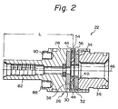
- the vibrator 22 comprises a vibrator body 26 which is resiliently supported, through elastomeric rings described later, by the casing 12 for vibratory movement with respect thereto. As shown in greater detail in FIG.
- the vibrator body 26 includes, in the illustrated embodiment, a generally cylindrical recessed housing 28, a pair of side plates 30 and 32 accommodated in the housing 28, a spacer ring or air-ejection ring 34 sandwiched between the side plates, and a backup ring 36 screwed into the housing 28 to air-tightly hold the members 30, 32, and 34 together.
- the front side plate 30, the intermediate spacer ring 34, and the rear side plate 32 together define a disk-like rotor chamber 38 in which is received a disk-shaped rotor 40 having a size slightly smaller than that of the chamber 38.
- the edges of the rotor 40 are preferably chamfered as described in U. S. Patent 4,453,919.
- the members 28, 30, 32, 36 and 40 are provided with aligned central apertures for passing a water pipe 42 (FIG. 1) therethrough.
- the apertures in the rear side plate 32 and the backup ring 36 also serve as exhaust ports for the air exhausted from the chamber 38.
- the ejection ring or spacer ring 34 is provided with a plurality of air nozzles 44. Although, for simplicity, these nozzles 44 are shown in FIGS. 1 and 2 as extending in the radial direction, actually they are offset with respect to the axis 46 (FIG. 2) of the chamber 38 as shown in FIG. 3 in such a manner that air under pressure is ejected therethrough substantially tangentially into the chamber 38 to generate a swirling stream of air therein. Compressed air from the dental unit is supplied to the air nozzles 44 through an air pipe 48 (FIG. 1), an air passage 50 in the joint 18, an annular air plenum 52 defined between the casing front piece 14 and the vibrator body 26, radial passages 54 in the housing 28 (FIG.
- the swirling air in the chamber 38 causes the rotor 40 to rotate about the axis of the chamber.
- the rotor 40 rotates, it wobbles like a coin spinning on a table and strikes the side plates 30 and 32 to impart vibration to the vibrator body 26.
- Resilient supports such as O-rings 70, 72, 74, and 76 are fitted around the vibrator body 26 to isolate the casing 12 from the vibration induced in the vibrator body 26, and to ensure vibratory movement of the body 26 with respect to the casing.
- the vibration generated in the vibrator body 26 is transmitted to a scaler tip 78 mounted to the vibrator body 26.
- the scaler tip 78 has a threaded portion 80 for connection to a threaded coupling section 82 of the vibrator housing 28.
- a pair of parallel pins 84 and 86 are provided to prevent the housing 28 from being rotated as the scaler tip 78 is screwed into the housing 28.
- the front ends of these pins are 84, 86 fixed to the casing front section 14 and the rear ends thereof are engaged through O-rings or elastomeric bushings within corresponding bores 88 and 90 in the housing 28.
- the scaler tip 78 has a straight shank section 94 and an inclined blade section 96. As the vibrator is operated, the vibration transmitted to the scaler tip causes the blade section 96 to oscillate with any points thereof oscillating along a generally circular or oval trajectory. Upon engagement with tooth surface, the oscillating blade section 96 imparts impact to accumulated calculus and removes it instantaneously from the tooth surface.
- the scaler tip 78 also has a water passage 98 for receiving a water supply from the water pipe 42. The water flowing out of the passage 98 is pulverized due to oscillation of the blade section 96 and cools the blade and the teeth and washes away the removed debris.
- a dental scaler as shown in FIGS. 1 and 2 was prepared.
- the rotor chamber 38 had an inner diameter of 7 mm and an axial thickness of 1.1 mm.
- the rotor 40 had an outer diameter of 6.5 mm and an axial thickness of 0.65 mm, with the diameter of inner aperture being 3.0 mm.
- the rotor 40 was made from a high speed steel alloy and was suitably heat treated.
- the scaler tip 78 had a length of 37 mm in the straightened state, excluding the length of the threaded section 80.
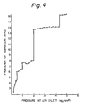
- the air inlet of the dental scaler was connected to an air compressor and the dental scaler was operated under varying air pressures. The air pressure was measured at the air inlet.
- the scaler tip was magnetized and the frequency of vibration of the scaler tip was measured by detecting the vibration of the magnetized tip via a magnetic pickup.
- the results were plotted in the gragh of FIG. 4, wherein the ordinate represents the frequency of vibration as detected and the abscissa indicates the air pressure at the air inlet of the dental scaler. From the graph, it will be appreciated that the scaler tip vibrates at frequencies roughly equal to or greater than 14 kHz when the air pressure at the air inlet of the dental scaler is greater than about 2 kg/cm2.
- the air pressure as measured at the inlet of the dental scaler is not equal to the supply pressure from the air compressor as regulated by the pressure relief valve.
- the rated supply pressure suitable to drive a turbine handpieces is about 5 kg/cm2 in a standard dental unit.
- the pressure at the air inlet of the dental scaler becomes about 3.5 kg/cm2.
- the pressure value of 3.5 kg/cm2 at the inlet of the scaler is equivalent to the rated supply pressure of 5 kg/cm2.
- the frequency developed with the inlet air pressure of 3.5 kg/cm2 is about 14 kHz.
- the dental scaler according to the invention is operable at the rated supply pressure of most dental units to generate vibration having a frequency which is very close to the lower boundary of ultrasonic range, i.e., 15 kHz.
- the only audible sound issuing from the dental scaler was the sound caused by flowing exhaust air. No perceptible level of annoying noise was observed.
- the scaling capability of the dental scaler which is considered to be represented by the amplitude of vibration of the scaler tip, was assessed by observing the formation of mist that resulted from water being pulverized due to high frequency oscillation of the blade section 96 of the scaler tip. Water supplied through the water passage 98 and flowing along the blade section 96 will be pulverized by cavitation if the scaler tip oscillates with an adequate amplitude.
- the tested dental scaler was operated under the inlet air pressures of around 3.5 kg/cm2, a good formation of mist was observed. This means that the dental scaler according to the invention exhibits a satisfactory scaling capability.
- the dental scaler of Takeshita as shown in FIG. 3 of U.S. Patent 4,453,919 was tested.
- the rotor chamber of the vibrator had an inner diameter of 7 mm and an axial thickness of 1.8 mm.
- the rotor had an outer diameter of 6.5 mm and an axial thickness of 1.1 mm.
- a similar scaler tip was used and the vibration was measured in a similar manner by making use of the same magnetic pickup. The results are plotted in the graph of FIG. 5.
- the frequency of vibration of this dental scaler was at maximum about 7 kHz, which is far lower than the ultrasonic range.
- a plurality of straight scaler tips having different length were prepared.
- These scaler tips were mounted to the dental scaler of Example 1 and the scaler was operated under an inlet air pressure of 3.5 kg/cm2.
- the frequency of vibration of the various scaler tips was measured in the same manner as in Example 1 and the results are plotted in the graph of FIG. 6.
- the dental scaler with scaler tips having effective lengths of from 33 to 40 mm operated at a frequency of vibration equal to or greater than 16 kHz. With the scaler tips having the effective length shorter than 33 mm, measurement was not possible because the amplitude of vibration was too small to be detected by the magnetic pickup.
- FIG. 7 Another vibrator having a vibrator housing shown in FIG. 7 was prepared.
- the housing 128 of FIG. 7 differed from the housing 28 of FIG. 2 in that the threaded coupling section for mounting the scaler tip was enlarged and stubbed and that the axial length L, as measured from the center of rotor chamber to the front end of the housing was 11.0 mm.
- Other components of the vibrator were the same as those used in Example 1.
- the sizes of the rotor chamber and the rotor were the same as those of Example 1.
- the assembled vibrator was mounted within a casing similar to that shown in FIG. 1 and the scaler tips used in Example 2 were mounted thereto.
- the dental scaler was operated and tested in the same manner as in Example 2. The results are shown in the graph of FIG. 8.
- the frequency of vibration generated by the dental scaler was about 15 kHz.
- the amplitude of vibration was too small to enable frequency measurement.
- the present invention has been described herein particularly with relation to an air-driven dental scaler, it is contemplated that the present invention is not limited thereby.
- the present invention is also applicable to air-driven dental instruments for condensing amalgam or for removing crown or other implants from teeth.
- the scaler tip 78 may be replaced with a suitable tool such as a crown remover or an amalgam condenser.
Landscapes
- Engineering & Computer Science (AREA)
- Mechanical Engineering (AREA)
- Health & Medical Sciences (AREA)
- Dentistry (AREA)
- Epidemiology (AREA)
- Life Sciences & Earth Sciences (AREA)
- Animal Behavior & Ethology (AREA)
- General Health & Medical Sciences (AREA)
- Public Health (AREA)
- Veterinary Medicine (AREA)
- Dental Tools And Instruments Or Auxiliary Dental Instruments (AREA)
- Medicines Containing Material From Animals Or Micro-Organisms (AREA)
Priority Applications (5)
| Application Number | Priority Date | Filing Date | Title |
|---|---|---|---|
| DE8686113258T DE3677225D1 (de) | 1986-09-26 | 1986-09-26 | Luftbetriebener zahnsteinentferner. |
| AT86113258T ATE60212T1 (de) | 1986-09-26 | 1986-09-26 | Luftbetriebener zahnsteinentferner. |
| EP86113258A EP0261272B1 (en) | 1986-09-26 | 1986-09-26 | Air-driven dental scaler |
| JP62234236A JPH0628669B2 (ja) | 1986-09-26 | 1987-09-18 | エア駆動式歯科用歯石除去装置 |
| US07/887,660 US5190456A (en) | 1986-09-26 | 1992-05-26 | Air-driven dental scaler |
Applications Claiming Priority (1)
| Application Number | Priority Date | Filing Date | Title |
|---|---|---|---|
| EP86113258A EP0261272B1 (en) | 1986-09-26 | 1986-09-26 | Air-driven dental scaler |
Publications (2)
| Publication Number | Publication Date |
|---|---|
| EP0261272A1 EP0261272A1 (en) | 1988-03-30 |
| EP0261272B1 true EP0261272B1 (en) | 1991-01-23 |
Family
ID=8195451
Family Applications (1)
| Application Number | Title | Priority Date | Filing Date |
|---|---|---|---|
| EP86113258A Expired EP0261272B1 (en) | 1986-09-26 | 1986-09-26 | Air-driven dental scaler |
Country Status (4)
| Country | Link |
|---|---|
| EP (1) | EP0261272B1 (ja) |
| JP (1) | JPH0628669B2 (ja) |
| AT (1) | ATE60212T1 (ja) |
| DE (1) | DE3677225D1 (ja) |
Families Citing this family (9)
| Publication number | Priority date | Publication date | Assignee | Title |
|---|---|---|---|---|
| US5749727A (en) * | 1994-06-30 | 1998-05-12 | Dentsply Research & Development Corp. | Transducer activated subgingival tool tip |
| DK0877579T3 (da) * | 1996-01-31 | 2004-03-22 | Dentsply Int Inc | Transduceraktiveret, subgingival værktøjsspids |
| JP3712829B2 (ja) * | 1997-05-15 | 2005-11-02 | 株式会社ミクロン | 空気動式バイブレータ |
| DE60045099D1 (de) | 1999-06-04 | 2010-11-25 | Dentsply Int Inc | Mikroendodontisches ultraschallwerkzeug mit einem g |
| DE102005028925A1 (de) * | 2005-06-22 | 2007-01-04 | Kaltenbach & Voigt Gmbh | Handgerät, insbesondere für dentale Zwecke, zur Abgabe einer pastösen Füllmasse |
| FR2972917B1 (fr) * | 2011-03-23 | 2013-04-05 | Jeremie Trommer | Piece a main dentaire et instrument dentaire, a interruption d'ecoulement |
| CN107662293A (zh) * | 2017-10-28 | 2018-02-06 | 东莞市优超精密技术有限公司 | Iso25‑sk06超声波刀柄结构 |
| CN107662288A (zh) * | 2017-10-28 | 2018-02-06 | 东莞市优超精密技术有限公司 | Hsk32‑er16超声波刀柄 |
| CN107695368A (zh) * | 2017-10-28 | 2018-02-16 | 东莞市优超精密技术有限公司 | Hsk32‑sk06超声波刀柄 |
Family Cites Families (2)
| Publication number | Priority date | Publication date | Assignee | Title |
|---|---|---|---|---|
| US4453919A (en) * | 1981-04-24 | 1984-06-12 | Micron Co., Ltd. | Dental scaler |
| US4427384A (en) * | 1982-07-22 | 1984-01-24 | Sertich Anthony T | Vibratory dental scaler |
-
1986
- 1986-09-26 AT AT86113258T patent/ATE60212T1/de not_active IP Right Cessation
- 1986-09-26 DE DE8686113258T patent/DE3677225D1/de not_active Expired - Fee Related
- 1986-09-26 EP EP86113258A patent/EP0261272B1/en not_active Expired
-
1987
- 1987-09-18 JP JP62234236A patent/JPH0628669B2/ja not_active Expired - Fee Related
Also Published As
| Publication number | Publication date |
|---|---|
| JPH0628669B2 (ja) | 1994-04-20 |
| JPS6399855A (ja) | 1988-05-02 |
| DE3677225D1 (de) | 1991-02-28 |
| EP0261272A1 (en) | 1988-03-30 |
| ATE60212T1 (de) | 1991-02-15 |
Similar Documents
| Publication | Publication Date | Title |
|---|---|---|
| US5190456A (en) | Air-driven dental scaler | |
| CA1231859A (en) | Endodontic unit | |
| US5531597A (en) | Transducer activated tool tip | |
| CA1160080A (en) | Dental scaler having scaling tip with rounded edge work surfaces particularly suitable for circular or ellipsoidal patterns of vibration | |
| US4283174A (en) | Dental scaler having scaling tip particularly suitable for circular or ellipsoidal patterns of vibration | |
| USRE30536E (en) | Ultrasonic device and method | |
| EP0261272B1 (en) | Air-driven dental scaler | |
| CA2397556A1 (en) | Torsional ultrasonic handpiece | |
| CA2323468A1 (en) | Torsional ultrasound handpiece | |
| JPS6410223B2 (ja) | ||
| US5749727A (en) | Transducer activated subgingival tool tip | |
| US4260380A (en) | Vibratory device with fluid transport means | |
| EP1234551A2 (en) | Air driven dental vibratory instrument with a replaceable vibrator module | |
| JP3703838B2 (ja) | 変換器作動のツール・チップ | |
| EP4096567B1 (en) | Tool for a medical treatment, preferably a dental treatment, and method for operating such a tool | |
| AU719732B2 (en) | Transducer activated subgingival tool tip | |
| JP2010042123A (ja) | 歯科用超音波振動治療装置 | |
| JP4048264B2 (ja) | 交換容易なバイブレータを備えた空気動式歯科用振動装置 | |
| US4527977A (en) | Gas-driven dental scaler having torque reaction means | |
| JP2003250814A (ja) | 振動付加型歯科用ハンドピース | |
| JPH022020B2 (ja) | ||
| JP2003284728A (ja) | 口腔洗浄器 | |
| JP4168420B2 (ja) | 交換容易なバイブレータを備えた空気動式歯科用振動ハンドピース | |
| CN117917230A (zh) | 梢部保持器、工具梢部和医疗工具 | |
| RU19259U1 (ru) | Наконечник стоматологический для удаления зубного камня |
Legal Events
| Date | Code | Title | Description |
|---|---|---|---|
| PUAI | Public reference made under article 153(3) epc to a published international application that has entered the european phase |
Free format text: ORIGINAL CODE: 0009012 |
|
| AK | Designated contracting states |
Kind code of ref document: A1 Designated state(s): AT CH DE FR GB IT LI |
|
| 17P | Request for examination filed |
Effective date: 19880521 |
|
| 17Q | First examination report despatched |
Effective date: 19890925 |
|
| GRAA | (expected) grant |
Free format text: ORIGINAL CODE: 0009210 |
|
| AK | Designated contracting states |
Kind code of ref document: B1 Designated state(s): AT CH DE FR GB IT LI |
|
| REF | Corresponds to: |
Ref document number: 60212 Country of ref document: AT Date of ref document: 19910215 Kind code of ref document: T |
|
| ET | Fr: translation filed | ||
| REF | Corresponds to: |
Ref document number: 3677225 Country of ref document: DE Date of ref document: 19910228 |
|
| ITF | It: translation for a ep patent filed | ||
| PLBE | No opposition filed within time limit |
Free format text: ORIGINAL CODE: 0009261 |
|
| STAA | Information on the status of an ep patent application or granted ep patent |
Free format text: STATUS: NO OPPOSITION FILED WITHIN TIME LIMIT |
|
| 26N | No opposition filed | ||
| REG | Reference to a national code |
Ref country code: GB Ref legal event code: IF02 |
|
| PGFP | Annual fee paid to national office [announced via postgrant information from national office to epo] |
Ref country code: FR Payment date: 20040908 Year of fee payment: 19 |
|
| PGFP | Annual fee paid to national office [announced via postgrant information from national office to epo] |
Ref country code: AT Payment date: 20040913 Year of fee payment: 19 |
|
| PGFP | Annual fee paid to national office [announced via postgrant information from national office to epo] |
Ref country code: GB Payment date: 20040922 Year of fee payment: 19 |
|
| PGFP | Annual fee paid to national office [announced via postgrant information from national office to epo] |
Ref country code: DE Payment date: 20040923 Year of fee payment: 19 |
|
| PGFP | Annual fee paid to national office [announced via postgrant information from national office to epo] |
Ref country code: CH Payment date: 20040929 Year of fee payment: 19 |
|
| PG25 | Lapsed in a contracting state [announced via postgrant information from national office to epo] |
Ref country code: IT Free format text: LAPSE BECAUSE OF NON-PAYMENT OF DUE FEES;WARNING: LAPSES OF ITALIAN PATENTS WITH EFFECTIVE DATE BEFORE 2007 MAY HAVE OCCURRED AT ANY TIME BEFORE 2007. THE CORRECT EFFECTIVE DATE MAY BE DIFFERENT FROM THE ONE RECORDED. Effective date: 20050926 Ref country code: GB Free format text: LAPSE BECAUSE OF NON-PAYMENT OF DUE FEES Effective date: 20050926 Ref country code: AT Free format text: LAPSE BECAUSE OF NON-PAYMENT OF DUE FEES Effective date: 20050926 |
|
| PG25 | Lapsed in a contracting state [announced via postgrant information from national office to epo] |
Ref country code: LI Free format text: LAPSE BECAUSE OF NON-PAYMENT OF DUE FEES Effective date: 20050930 Ref country code: CH Free format text: LAPSE BECAUSE OF NON-PAYMENT OF DUE FEES Effective date: 20050930 |
|
| PG25 | Lapsed in a contracting state [announced via postgrant information from national office to epo] |
Ref country code: DE Free format text: LAPSE BECAUSE OF NON-PAYMENT OF DUE FEES Effective date: 20060401 |
|
| REG | Reference to a national code |
Ref country code: CH Ref legal event code: PL |
|
| GBPC | Gb: european patent ceased through non-payment of renewal fee |
Effective date: 20050926 |
|
| PG25 | Lapsed in a contracting state [announced via postgrant information from national office to epo] |
Ref country code: FR Free format text: LAPSE BECAUSE OF NON-PAYMENT OF DUE FEES Effective date: 20060531 |
|
| REG | Reference to a national code |
Ref country code: FR Ref legal event code: ST Effective date: 20060531 |