EP0260993B1 - Farbfernseh-Dekoder - Google Patents
Farbfernseh-Dekoder Download PDFInfo
- Publication number
- EP0260993B1 EP0260993B1 EP87308302A EP87308302A EP0260993B1 EP 0260993 B1 EP0260993 B1 EP 0260993B1 EP 87308302 A EP87308302 A EP 87308302A EP 87308302 A EP87308302 A EP 87308302A EP 0260993 B1 EP0260993 B1 EP 0260993B1
- Authority
- EP
- European Patent Office
- Prior art keywords
- output
- decoder
- variable
- signal
- dimensional
- Prior art date
- Legal status (The legal status is an assumption and is not a legal conclusion. Google has not performed a legal analysis and makes no representation as to the accuracy of the status listed.)
- Expired
Links
- 230000001419 dependent effect Effects 0.000 claims 2
- 230000001934 delay Effects 0.000 description 11
- 230000001965 increasing effect Effects 0.000 description 8
- 238000010586 diagram Methods 0.000 description 5
- 238000001228 spectrum Methods 0.000 description 5
- 238000000034 method Methods 0.000 description 4
- 238000012545 processing Methods 0.000 description 3
- 230000003044 adaptive effect Effects 0.000 description 2
- 230000003111 delayed effect Effects 0.000 description 2
- 230000000694 effects Effects 0.000 description 2
- 230000001939 inductive effect Effects 0.000 description 2
- 238000012935 Averaging Methods 0.000 description 1
- 238000004458 analytical method Methods 0.000 description 1
- 238000013461 design Methods 0.000 description 1
- 238000001514 detection method Methods 0.000 description 1
- 230000002708 enhancing effect Effects 0.000 description 1
- 238000001914 filtration Methods 0.000 description 1
- 230000001771 impaired effect Effects 0.000 description 1
- 230000010363 phase shift Effects 0.000 description 1
- 238000000926 separation method Methods 0.000 description 1
- 230000001629 suppression Effects 0.000 description 1
- 230000001360 synchronised effect Effects 0.000 description 1
- 238000012546 transfer Methods 0.000 description 1
Images


Classifications
-
- H—ELECTRICITY
- H04—ELECTRIC COMMUNICATION TECHNIQUE
- H04N—PICTORIAL COMMUNICATION, e.g. TELEVISION
- H04N9/00—Details of colour television systems
- H04N9/77—Circuits for processing the brightness signal and the chrominance signal relative to each other, e.g. adjusting the phase of the brightness signal relative to the colour signal, correcting differential gain or differential phase
- H04N9/78—Circuits for processing the brightness signal and the chrominance signal relative to each other, e.g. adjusting the phase of the brightness signal relative to the colour signal, correcting differential gain or differential phase for separating the brightness signal or the chrominance signal from the colour television signal, e.g. using comb filter
Definitions
- the present invention relates to a colour television decoder.
- a decoder may be used for decoding PAL and NTSC colour television signals to provide separate colour components, i.e. either red green and blue (RGB) or luminance (Y) and R-Y (V) and B-Y (U) colour difference signals, for the purpose of direct display of a television picture or for the purpose of processing the decoded signal, possibly before re-encoding into a similar or different system such as PAL, NTSC, SECAM, C-MAC or other format.
- the colour information in the PAL or NTSC system is transmitted as modulation of a subcarrier signal added to the luminance signal.
- the modulated colour subcarrier is herein referred to as the chrominance signal.
- the chrominance signal is removed from the input signal to provide luminance by the use of a notch (band-stop) filter designed to suppress the colour subcarrier frequency and also reduce the amplitude of the side-bands generated as a result of its modulation.
- a notch band-stop filter designed to suppress the colour subcarrier frequency and also reduce the amplitude of the side-bands generated as a result of its modulation.
- this band-stop filter is a poor compromise between adequately suppressing the unwanted chrominance and undesirably suppressing the wanted luminance information at frequencies near to the subcarrier. Inadequate suppression of the chrominance signal results in a fine dot pattern on the displayed luminance signal commonly known as cross-luminance.
- the chrominance information in such a conventional decoder is separated from the input signal by a band-pass filter designed to select the colour subcarrier and its associated side-bands but reject as far as possible the luminance signal. Again the compromise is unsatisfactory and much unwanted luminance information passes into the chrominance path where it is decoded to produce spurious colour effects commonly known as cross-colour.
- a commonly used technique to reduce cross-colour in a PAL decoder is known as delay line decoding.
- the chrominance signal on one line is combined with the chrominance from the previous line which has been delayed by a period of one line plus or minus a period of one quarter of a subcarrier cycle.
- This technique reduces cross-colour but because of the line averaging also reduces vertical colour resolution.
- horizontal colour resolution is also reduced.
- cross-colour may be reduced and loss of resolution in vertical luminance is also improved.
- the comb filter decoder however produces unsatisfactory decoding where the picture contains significant colour changes from one television line to the next. The colour subcarrier is then not adequately suppressed in the luminance output and the vertical resolution of the chrominance outputs is impaired.
- Adaptive decoders of the type described in U.K. Patent Application GB-A-2153624 attempt to overcome these limitations by changing the response of the decoder from a comb filter to one incorporating a notch filter if a change in colour from one line to the next exceeds a fixed threshhold. This technique improves the decoder performance where distinct colour changes occur as in some electronically generated pictures, but frequently fails to operate adequately on picutres containing more random changes in luminance information or where a more gradual change in picture colour occurs in a scene.
- a colour television decoder comprising a continuously variable two dimensional finite impulse response filter having: an input for receiving an input colour video signal representing picture information; an output for supplying chrominance signals; first delay means coupled to said input for providing a plurality of signals; and first variable combining means for combining the plurality of signals and said decoder further comprising first control means for continuously controlling the first variable combining means by determining the proportions of the plurality of signals to be combined in accordance with the picture information, characterised in that the plurality of signals provided by said first delay means represent a two dimensional pattern of picture points and said first variable combining means combines said plurality of signals linearly.
- the output of the variable filter is connected to a first input of first subtracting means whose second input is connected to the output of second delay means for delaying the input colour video signal so as to provide a luminance signal at the output of the first subtracting means.
- the first delay means includes a first delaying circuit for receiving the input colour video signal and for providing a delay equal to one line period of the input colour video signal, and a second delaying circuit for receiving the output of the first delaying circuit and for providing a delay equal to one line period of the input colour video signal, the decoder further comprising second subtracting means for subtracting the output of the second delaying circuit from the input colour video signal, second and third variable combining means for linearly combining the output of the variable filter with the output of the second subtracting means in variable proportions, and second control means for controlling the variable proportions of the second and third variable combining means in accordance with picture information represented by the input colour video signal.
- phase shifting means is provided between the second subtracting means and the second and third variable combining means.
- the first control means comprises a first two dimensional bandpass filter having a first pass band centred on predetermined horizontal and vertical spatial frequencies, and having an output connected to a first rectifier.
- the first control means further comprises a quadruple two dimensional bandpass filter having second, third, and fourth and fifth pass bands and having an output connected to a second rectifier, and third subtracting means for subtracting the output of the second rectifier from the output of the first rectifier, the second and third pass bands having a horizontal centre frequency less than that of the first pass band and the fourth and fifth pass bands having a horizontal centre frequency greater than that of the first pass band, the second and fourth pass bands having a vertical centre frequency less than that of the first pass band and the third and fifth pass bands having a vertical centre frequency greater than that of the first passband.
- the second control means comprises a second two dimensional bandpass filter having a sixth pass band centred on a predetermined horizontal spatial frequency and zero vertical spatial frequency, and having an output connected to a third rectifier.
- the second control means further comprises a double two dimensional bandpass filter having seventh and eighth pass bands and having an output connected to a fourth rectifier, and fourth subtracting means for subtracting the output of the fourth rectifier from the output of the third rectifier, the seventh and eighth pass bands having a non zero vertical centre frequency, the seventh pass band having a horizontal centre frequency less than that of the sixth pass band filter and the eighth pass band having a horizontal centre frequency greater than that of the sixth pass band.
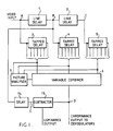
- Figure 1 shows a colour television decoder for separating the chrominance and luminance signals from a video input signal of the type in which the chrominance signal shares the frequency spectrum occupied by the luminance signal.
- Conventional video signals of this type employ an interleaving technique such that a subcarrier frequency is quadrature-modulated by two colour difference signals with the frequency components of the modulated signal being interleaved with the frequency components of the luminance signal.
- NTSC NTSC
- PAL PAL
- the decoder may be provided in a colour television receiver or monitor with the video input signal being supplied from a vision detector, the luminance signal being supplied to a matrixing circuit, and the chrominance signal being supplied to synchronous demodulators for supplying the colour difference signals to the matrixing circuit.
- the decoder may be used in other applications for processing, for instance prior to re-encoding in a different format.
- the decoder may be used for any of these.
- the commonest NTSC encoding format operates at 60 fields per second interlaced to provide 30 frames per second with 525 lines in each frame.
- the commonest PAL encoding format uses 50 fields per second interlaced to provide 25 frames per second with 625 lines in each frame. For the purposes of illustration only, the following description will refer to the latter format.
- the input video signal A is supplied to the input of a line delay 1 which provides a delay equal to one line period of the picture (64 micro seconds).
- the output B of the line delay 1 is supplied to the input of a second line delay 2 of identical type providing an output C.
- the signals A, B, and C thus refer to three picture points arranged vertically in three consecutive lines of the picture.
- the signals A, B and C are supplied to the inputs of tapped delays 3, 4, and 5, respectively, each having a delay of between 0.5 and 2 micro seconds.
- the signals at the output taps of the delays 3, 4, and 5 represent picture points horizontally displaced along a displayed picture line and the immediately preceding and succeeding lines.
- the signals represent a two-dimensional pattern or array of picture points with the currently displayed picture point being substantially at the centre of the array.
- variable combiner 6 having an output for providing the output chrominance signal D of the decoder.
- the variable combiner 6 linearly combines the signals from the output taps of the tapped delays 3, 4 and 5 such that each signal is multiplied by a variable positive or negative coefficient and the resulting products are summed.
- the arrangement of delay lines and the variable combiner thus forms a variable two-dimensional finite impulse response filter.
- the response of the filter can be changed by varying the coefficient relating to each delay output to alter the amplitude and polarity thereof.
- the filter is normally used with a bandpass response to pass the chrominance signal while substantially rejecting the luminance signal.
- the variable combiner 6 can be controlled in such a way as to change the vertical, horizontal, or diagonal resolution of the chrominance signal.
- the output taps of the tapped delays 3, 4, and 5 are also supplied to the inputs of a picture analyser 7.
- the picture analyser 7 is arranged to determine the picture content of the picture area represented by the array of picture points. For instance, the analyser can detect picture information such as vertical luminance information, the presence of colour, vertical or horizontal colour changes, and the like.
- the picture analyser 7 analyses this information and supplies suitable coefficient control signals to the variable combiner 6 so as to change the response of the filter in order to provide optimum separation of luminance and chrominance signals for each picture point.
- the signal B is supplied to a delay 14 arranged to provide a delay time so that the output signal E corresponds to the picture point currently being displayed, i.e. the centre of the array of picture points.
- a delay 14 arranged to provide a delay time so that the output signal E corresponds to the picture point currently being displayed, i.e. the centre of the array of picture points.
- one of the output taps of the tapped delay 4 may be able to provide the signal E.
- the signal E is supplied to one input of a subtractor 15, whose other input receives the chrominance signal D from the variable combiner 6.
- the subtractor 15 thus provides the luminance signal at its output.
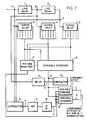
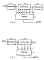
- the decoder shown in Figure 2 comprises line delays 1 and 2, tapped delays 3, 4 and 5, a variable combiner 6, a picture analyser 7, a delay 14 and a subtractor 15 identical to or corresponding to those parts in Figure 1. Accordingly, these parts will not be further described.
- the decoder of Figure 2 is intended for use with PAL encoded signals, and further comprises a subtractor 8 have first and second inputs which receive the signals A and C, respectively.
- the subtractor 8 forms the difference H between these signals and supplies this via a 90° phase shifter 9 to the input of a bandpass filter 10.
- the output G of the filter 10 is supplied to first inputs of variable combiners 11 and 12.
- the output D of the variable combiner 6 is supplied to second inputs of the variable combiners 11 and 12.
- the variable combiners are controlled by a control signal supplied by the picture analyser 7.
- the signal H from the subtractor 8 contains chrominance information which is shifted in phase by 90° in the phase shifter 9 and filtered in the bandpass filter 10 to provide a chrominance only signal G.
- the variable combiner 11 adds together the signals D and G in variable proportions, under control of the picture analyser, to provide an output signal J equal to x D + (1 - x) G, where x is a variable coefficient between zero and one depending on the value of the control signals from the picture analyser 7.
- the variable combiner 12 subtracts the input signals D and G to produce an output signal K equal to x D - (1 - x) G.
- the output signals J and K from the variable combiners 11 and 12 are the chrominance colour difference signals and may be supplied to conventional R - Y and B - Y demodulaters.
- the variable combiners 11 and 12 may be controlled so as to allow the vertical chrominance response to be varied in accordance with the picture content.
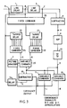
- the decoder shown in Figure 3 is similar to that shown in Figure 2 but the tapped delays 3, 4 and 5 and the variable combiner 6 of Figure 2 are replaced by a fixed combiner 20, tapped delays 21 and 23, fixed combiners 22 and 24, and a variable combiner 25.
- the other parts of the decoder of Figure 3 correspond to parts in Figure 2 and will not be described further.
- the signals A, B, and C are supplied to the inputs of the fixed combiner 20 where they are linearly combined with predetermined signs and in predetermined proportions.
- the output of the fixed combiner 20 is supplied to the input of the tapped delay 21, whose output taps are connected to the inputs of the input combiner 22 and to the picture analyser 7 (the input connections with the picture analyser 7 are not shown in Figure 3 for the sake of clarity).
- the signal B is supplied to the input of the tapped delay 23, whose output taps are connected to the inputs of the fixed combiner 24 and to the picture analyser 7.
- the output signals R and S of the fixed combiners 22 and 24 are supplied to the variable combiner 25, whose output signal T is supplied to the subtractor 15 and to the variable combiners 11 and 12.
- the fixed combiner 20, the tapped delay 21, and the fixed combiner 22 provide a fixed two-dimensional filter arranged to pass the chrominance signals.
- the tapped delay 23 and the fixed combiner 24 provide a one-dimensional (horizontal) chrominance filter.
- the variable combiner combines the signals R and S in accordance with the ratio p R + (1 - p) S, where p is a variable coefficient between 0 and 1 controlled by the picture analyser 7.
- the chrominance signal T is substantially free from luminance information, and the effective horizontal and vertical resolutions of this signal are defined by the fixed combiners 22 and 24 and the variable combiner 25.
- the decoder of Figure 3 is shown with the variable combiners 11 and 12 for use with a PAL encoded signal, the signal T may be used as the chrominance signal directly, for instance for NTSC encoded signals.
- the fixed combiner 20 would combine proportions of the signals A, B, and C so that the output signal has a minimum response to vertical luminance signals and a maximum response to diagonal picture information. This may be achieved by forming the output signal equal to B - 1 ⁇ 2 A - 1 ⁇ 2 C.
- the delays provided by the tapped delay output taps and the linear combination formed by the combiner 22 are chosen to provide the signal R with a maximum response at the colour subcarrier frequency and a band width substantially equal to the band width of the chrominance signal.
- the tapped delay 23 and the fixed combiner 24 are arranged to provide the signal S with a maximum response at the colour subcarrier frequency and a band width substantially equal to that of the chrominance signal.
- the band width of the tapped delay 23 and the fixed combiner 24 is lower than that of the tapped delay 21 and the combiner 22.
- the signals R and S constitute two separated chrominance signals.
- the vertical response of the signal R is reduced because of the action of the vertical filter comprising the fixed combiner 20.
- the vertical response or resolution of the signal S is not restricted, but its horizontal response or resolution may be chosen to be restricted.
- the variable combiner 25 combines different proportions of the signals R and S so as to adjust the horizontal and vertical response of the chrominance output T in accordance with the control signal supplied by the picture analyser 7. Because the signal T is subtracted from the signal E, the luminance signal at the output of the subtractor 15 is also a function of the control signal of the picture analyser 7.
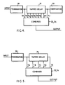
- the tapped delays 21 and 23 may be provided by a conventional type of inductive delay line of the type shown in Figure 4.
- the input is connected via a suitable termination impedance 30 to the tapped delay line 31, whose output is similarly provided with a suitable termination impedance 32.
- the impedances of the termination impedances 30 and 32 are matched to the impedance of the delay line 31 so as to avoid reflections.
- the outputs TA to TJ are connected to the inputs of the fixed combiner 22 or 24.
- the tapped delay line 31 conveniently provides a delay equal to a multiple of the period of the subcarrier frequency and the taps are conveniently spaced at multiplies of half this period.
- the coefficients of the linear combination in the combiner 22 or 24 are made symmetrical about the centre of the delay line so that the output of the combiner is equal to a A + b B + c C + d D + e E + d F + c G + b H + a J, where a, b, c, d, and e are fixed positive or negative constants defining the filter.
- the tapped delay can be simplified as shown in Figure 5 by using a delay line of half the length of that in Figure 4 and terminating the output of the delay line in a high impedance instead of the characteristic impedance of the delay line, for instance by leaving the output open circuit.
- the signal is then reflected at the mis-matched impedance and, by providing the coefficients a, b, c, d, and e in the combiner, the same transfer function as that of the arrangement of Figure 4 is provided by the arrangement of Figure 5.
- the phase shifter 9 and the filter 10 of the decoders shown in Figures 2 and 3 may be constituted by the arrangement shown in Figure 6, which comprises input and output termination impedances 40 and 41, a tapped inductive delay line 42, and a fixed combiner 43.
- the delay line 42 has an even number of taps spaced by multiples of half the period of the subcarrier frequency.
- coefficients a, b, c, and d are suitably choosen and the combiner performs the combination a A + b B + c C + d D - d E - c F - b G - a H, the coefficients thus being anti-symmetric with respect to magnitude and polarity about the centre of the delay line.
- Figure 7 illustrates an alternative arrangement to that of Figure 6 allowing the use of a shorter delay line 44.
- the delay line taps are spaced by half the period of the subcarrier frequency with the final tap being spaced by a period of a quarter of the subcarrier frequency from the end of the delay line.
- the end of the delay line is terminated by a low impedance or short circuit 45 so that signals travelling down the delay line are reflected with inversion.
- the picture analyser may comprise one or more comb filters or two-dimensional spacial filters, together with rectifiers for measuring the outputs of the filter or filters.
- the purpose of the filters is to separate vertical and diagonal picture information at frequencies near to that of the colour subcarrier.
- the rectified outputs of the filters provide control signals to the variable combiner 25 depending on the picture information contained in the picture area covered by the array of picture points.
- the rise and fall times of the control signals are similar to the rise and fall times of the chrominance signal.
- the output of the picture analyser is arranged such that an increase in the amount of diagonal picture information, corresponding to frequencies near to (n + 1 ⁇ 2) fh where fh is the line frequency and n is a positive integer, increases the proportion of the signal S and correspondingly reduces the proportion of the signal R making up the signal T. Conversely, signals containing vertical picture information, corresponding to frequencies near to nfh, cause the proportion of the signal S to be reduced and the proportion of the signal R to be increased.
- the response of the control signal to the picture information at different angles may be modified by the use of two or more filters and rectifiers with the outputs of the rectifiers combined, for instance added or subtracted, to form the final control signal for the variable combiner 25.
- Figure 8 shows a form of the picture analyser 7 which is particularly suitable for use in the decoder of Figure 3.
- the analyser receives at its input the signals A, B, and C and the signals from the output taps of the tapped delays 21 and 23 at an input 50.
- the input 50 is connected to first, second, and third filters 51 to 53 respectively.
- Each of the filters 51 to 53 comprises a two-dimensional finite impulse response filter provided by a fixed combiner similar to the fixed combiners 22 and 24, with coefficients selected so as to provide the desired response.
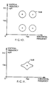
- the first filter 51 has a two dimensional bandpass response of the type illustrated in Figure 9, which is a graph of vertical spacial frequency in cycles per picture height against horizontal frequency in megahertz.
- the first filter 51 has a peak response or centre frequency at a horizontal frequency near to the subcarrier frequency and a vertical frequency of about 156 cycles per picture height. This corresponds to diagonal picture information.
- the output of the filter 51 is rectified by a rectifier 55. Although this signal could be used to control the variable combiner 25, it is preferred to subject it to further processing as follows.
- the filter 52 is a quadruple bandpass filter having four peaks as illustrated in Figure 10.
- the centre frequencies of the four peaks are offset from the centre frequency of the filter 51 horizontally by + and - one megahertz, and are located approximately at 78 and 235 cycles per picture height.
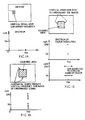
- the output of the filter 52 is rectified by a rectifier 56 and supplied to one input of a subtractor 57 whose other input is connected to the output of the rectifier 55. The effect of this is to modify the response shown in Figure 9 to the response shown in Figure 11, which improves the control of the variable combiner by enhancing the detection of vertical and horizontal edges of coloured picture areas.
- variable combiners 11 and 12 The action of the variable combiners 11 and 12 is to modify further the vertical and horizontal response of the decoder to PAL encoded signals.
- the vertical band width of the chrominance signal is reduced as the contribution from the signal G to the output signals J and K is increased.
- the filter 10 may be designed such that, as the vertical band width is reduced, the horizontal band width increases.
- variable combiner 25 and the picture analyser 7 cooperate such that, in the presence of vertical picture information, the contribution of the signal T to the signals J and K is increased whereas, as diagonal picture information increases, the contribution of signal G increases.
- the control signal for instance at the output of the rectifier 55 or at the output of the subtractor 57, for the variable combiner 25 may be also be used to control the variable combiners 11 and 12.
- the filter 53 has a bandpass response with a peak response or centre frequency at a horizontal frequency near to the subcarrier frequency and a vertical frequency of zero, as shown in Figure 12.
- the output of the filter 53 is rectified by a rectifier 58, whose output signal may be used to control the variable combiners 11 and 12 so as to increase the contribution of the signal T.
- Figures 14 to 16 illustrate the operation of the decoder of Figure 3 incorporating the picture analyser 7 of Figure 8 and serve to illustrate operation in response to certain picture configurations.
- the upper part of Figure 14 illustrates a picture having vertical detail at near to the subcarrier frequency, and the lower part of Figure 14 shows the spectrum of this signal.
- the filter response shown in Figure 11 is such that the control signal from the subtractor 57 is low.
- the variable combiner 25 therefore mainly passes the signal R to form the signal T.
- the signals A, B, and C are substantially equal, and the vertical filtering action of the combiner 20 provides a substantially zero signal R.
- the luminance signal from the subtractor 15 is therefore substantially equal to the signal E, which is the delayed signal B.
- Figure 15 illustrates horizontal scanning through a coloured area encountering vertical edges of this coloured area.
- the middle part of Figure 15 shows the spectrum of the signal from the coloured area itself, comprising two discreet signals of the same horizontal frequency.
- the lower part of Figure 15 shows the spectrum for the vertical edges which provide side band signals displaced vertically.
- the side bands fall within the pass band of the filter response of Figure 10 which reduces the level of the control signal from the subtractor 57 to the variable combiner 20.
- the contribution of the signal R to the signal T is increased, thus increasing the horizontal chrominance band width.
- the control signal at the output of the subtractor 59 is reduced, thus increasing the contribution of the signal G to the signals J and K, providing maximum horizontal chrominance band width and reduced vertical band width.
- the upper part of Figure 16 illustrates a similar coloured area to that shown in Figure 15 but this time with respect to the horizontal edges.
- scanning of the horizontal edges produces vertical side bands of the chrominance signal falling within the pass bands of the filters 51 and 52 ( Figures 9 and 11).
- the contribution of the signal S to the signal T is therefore increased and the vertical response of the chrominance signal is enhanced, thus giving improved vertical band width of the chrominance signal.
- the subtractor 15 removes the vertical side bands from the luminance signal. Also, the contribution of the signal T to the signals J and K is increased so as to improve the vertical chrominance resolution.
Landscapes
- Engineering & Computer Science (AREA)
- Multimedia (AREA)
- Signal Processing (AREA)
- Processing Of Color Television Signals (AREA)
Claims (18)
- Farbfernseh-Dekoder, der einen kontinuierlich variablen zweidimensionalen, finiten Impulsausschlagsfilter beinhaltet (1-6, 20-25; 1, 2, 20-25) und aufweist:
Einen Input, um ein Inputcolor-Videosignal (A) aufzunehmen, das Bildinformation darstellt;
einen Output, um Chrominanzsignale (D) zu liefern;
erste Verzögerungsvorrichtungen (1-5; 1, 2), die mit besagtem Input gekoppelt sind, um eine Vielzahl von Signalen bereitzustellen; und erste variable Verbindungseinrichtungen (6; 25), um die Vielzahl von Signalen zu kombinieren, und wobei besagter Dekoder weiterhin eine erste Steuereinrichtung (7) umfaßt, um kontinuierlich die erste variable Verbindungseinrichtung zu steuern, indem die Proportionen der Vielfalt der Signale bestimmt werden, die in Übereinstimmung mit der Bildinformation kombiniert werden sollen, dadurch gekennzeichnet, daß die Vielzahl von Signalen, die durch besagte erste Verzögerungseinrichtung bereitgestellt wird, eine zweidimensionale Anordnung von Bildpunkten repräsentiert und daß besagte erste variable Verbindungseinrichtung besagte Vielzahl von Signalen linear kombiniert. - Dekoder gemäß Anspruch 1, dadurch gekennzeichnet, daß die erste Verzögerungsvorrichtung einen ersten Verzögerungskreis (1) mit einschließt, um eine Verzögerung zu schaffen, die gleich einer Leitungsperiodendauer des Input-Color-Videosignals ist, und einen zweiten Verzögerungskreis (2), um eine Verzögerung zu schaffen, die gleich einer Leitungsperiodendauer des Input-Color-Videosignales ist und mit dem Output (B) des ersten Verzögerungskreises (1) verbunden ist.
- Dekoder gemäß Anspruch 2, der weiterhin eine zweite Verzögerungseinrichtung (14) umfaßt, um den Output (B) des ersten Verzögerungskreises (1) zu verzögern und eine erste Subtraktionseinrichtung (15) mit einem ersten Input, der mit der ersten variablen Verbindungseinrichtung (6; 25) verbunden ist und einen zweiten Input, der mit der besagten zweiten Verzögerungsvorrichtung (14) verbunden ist, und einen Output für die Lieferung eines Luminanzsignals.
- Dekoder gemäß Anspruch 3, der weiterhin eine zweite Subtraktionseinrichtung (8) umfaßt, um das Input-Color-Videosignal (A) zu subtrahieren, und den Output (C) des zweiten Verzögerungskreises (2), eine Einrichtung zur Phasenverschiebung (9) zur Phasenverschiebung des Outputs (H) der zweiten Subtraktionseinrichtung (8).
- Dekoder gemäß Anspruch 4, wobei besagte Einrichtung zur Phasenverschiebung (9) einen 90°-Phasenverschieber aufweist, der in Serie von einem Bandpaßfilter (10) gefolgt wird.
- Dekoder gemäß Anspruch 4 oder 5, der weiterhin zweite und dritte variable Verbindungseinrichtungen (11, 12) zum linearen Kombinieren des Outputs (D; T) der ersten variablen Verbindungseinrichtungen (6; 25) mit dem Output (G) der Einrichtung zur Phasenverschiebung (9) in variable Proportionen aufweist, und eine zweite Steuereinrichtung (7) zur Steuerung der zweiten und dritten variablen Verbindungseinrichtung (11, 12) in Übereinstimmung mit der Bildinformation.
- Dekoder gemäß einem der Ansprüche 2 bis 6, wobei besagter erster Verzögerungskreis (1) weiterhin umfaßt:
Erste, zweite und dritte abgegriffene Verzögerungsleitungen (3, 4, 5), die Inputs haben, die jeweils verbunden sind mit besagtem Input-Color-Videosignal (A), dem Output (B) des besagten ersten Verzögerungskreises (1) und dem Output (C) des besagten zweiten Verzögerungskreises (2); jede besagte abgegriffene Verzögerungsleitung hat eine Vielzahl von Output-Abgriffen; und besagte variable Verbindungseinrichtung (6) weist einen variablen Verbindungskreis auf, der eine Vielzahl von Inputs hat, die mit besagten Output-Abgriffen der besagten ersten, zweiten und dritten abgegriffenen Verzögerungsleitungen (3, 4, 5) verbunden sind, und einen Output (D, E), der besagten Output des variablen, zweidimensionalen finiten Impulsausschlagfilters versorgt. - Dekoder gemäß Anspruch 7, wobei besagte erste Steuereinrichtung (7) einen Bild-Analysator aufweist, der eine Vielzahl von Inputs hat, die mit besagten Output-Abgriffen der besagten ersten, zweiten und dritten abgegriffenen Verzögerungsleitungen verbunden sind und einen Output, der ein Steuersignal zum kontinuierlichen Steuern besagter erster variabler Verbindungseinrichtung (6) bereitstellt, um den vertikalen Ausschlag des zweidimensionalen Filters zu verändern.
- Dekoder gemäß einem der Ansprüche 2 bis 6, wobei besagte erste Verzögerungsvorrichtung weiterhin umfaßt:
einen ersten festen Verbindungskreis (20), der Inputs hat, die jeweils verbunden sind mit besagtem Input-Color-Videosignal (A), dem Output (B) von besagtem ersten Verzögerungskreis (1) und dem Output (C) von besagtem zweiten Verzögerungskreis (2);
erste und zweite abgegriffene Verzögerungsleitungen (23, 21), die jeweils besagten Output (B) von besagtem ersten Verzögerungskreis (1) und besagten Output von besagtem ersten festen Verbindungskreis (20) aufnehmen; jede der besagten ersten und zweiten abgegriffenen Verzögerungsleitungen haben eine Vielzahl von Output-Abgriffen;
zweite und dritte feste Verbindungskreise (24, 22), wobei jeder eine Vielzahl von Inputs hat, die jeweils mit besagten Mehrzahlen von Output-Abgriffen von besagten ersten und zweiten abgegriffenen Verzögerungsleitungen (23, 21) und jeweils Outputs (S, R) hat; und
besagte erste variable Verbindungseinrichtung (25), die besagte Outputs (S, R) von besagten festen Verbindungskreisen (24, 22) linear verbindet und besagten Output (T) des variablen zweidimensionalen finiten Impulsausschlagfilters schafft. - Dekoder gemäß einem der vorhergehenden Ansprüche, wobei besagte erste Steuereinrichtung (7) zumindest diagonal Bildinformation in besagter Vielzahl der Signale mißt, die die besagte zweidimensionale Anordnung von Bildpunkten darstellt, um die erste variable Verbindungseinrichtung (6, 25) zu steuern.
- Dekoder gemäß Anspruch 10, wobei besagte erste Steuereinrichtung (7) besagte diagonale Bildinformation ermittelt und die vertikale Bandbreite des variablen zweidimensionalen Filters reduziert.
- Dekoder gemäß Anspruch 11, wobei besagte erste Steuereinrichtung (7) simultan die horizontale Bandbreite des variablen zweidimensionalen Filters erhöht.
- Dekoder gemäß einem der vorhergehenden Ansprüche, dadurch gekennzeichnet, daß die erste Steuervorrichtung (7) einen ersten zweidimensionalen Bandpaßfilter (51) enthält, der einen ersten Durchlaßbereich hat, der auf vorbestimmte horizontale und vertikale räumliche Frequenzen gerichtet ist, und einen ersten Demodulator (55) (rectifier), der mit dem ersten zweidimensionalen Bandpaßfilter (51) verbunden ist.
- Dekoder gemäß Anspruch 13, wenn dieser von Anspruch 4 abhängig ist, dadurch gekennzeichnet, daß die erste Steuervorrichtung (7) weiterhin einen vierfachen zweidimensionalen Bandpaßfilter (52) enthält, der zweite, dritte, vierte und fünfte Durchlaßbereiche hat, einen zweiten Demodulator (56), der mit dem vierfachen zweidimensionalen Bandpaßfilter (52) verbunden ist und dritte Subtraktionseinrichtungen (57), um die Outputs des ersten und zweiten Demodulators (55, 56) zu subtrahieren, wobei die zweiten und dritten Durchlaßbereiche eine geringere horizontale Mittelfrequenz haben als der erste Durchlaßbereich und die vierten und fünften Durchlaßbereiche haben eine größere horizontale Mittelfrequenz als der erste Durchlaßbereich, die zweiten und vierten Durchlaßbereiche haben eine geringere vertikale Mittelfrequenz als der erste Durchlaßbereich und der dritte und fünfte Durchlaßbereich haben eine größere vertikale Mittelfrequenz der erste Durchlaßbereich.
- Dekoder gemäß Anspruch 14, wenn dieser von Anspruch 6 abhängig ist, dadurch gekennzeichnet, daß die zweite Steuereinrichtung (7) einen zweiten zweidimensionalen Bandpaßfilter (53) enthält, der einen sechsten Durchlaßbereich hat, der auf eine vorher bestimmte horizontale räumliche Frequenz und auf eine null-vertikale räumliche Frequenz gerichtet ist und einen dritten Demodulator (58), der mit dem zweiten 2-dimensionalen Bandpaßfilter (53) verbunden ist.
- Dekoder gemäß Anspruch 15, dadurch gekennzeichnet, daß die zweite Steuereinrichtung (7) weiterhin einen doppelten zweidimensionalen Bandpaßfilter (52) enthält, der siebte und achte Durchlaßbereiche hat, einen vierten Demodulator (56), der mit dem doppelten zweidimensionalen Bandpaßfilter (52) verbunden ist und vierte Subtraktionseinrichtungen (59), um die Outputs des dritten und vierten Demodulators (56, 58) zu subtrahieren, wobei die siebten und achten Durchlaßbereiche eine vertikale Mittelfrequenz ungleich Null haben, der siebte Durchlaßbereich hat eine geringere horizontale Mittelfrequenz als der sechste Durchlaßbereich und der achte Durchlaßbereich hat eine größere horizontale Mittelfrequenz als der sechste Durchlaßbereich.
- Dekoder gemäß Anspruch 16, in dem der Output von besagtem ersten Demodulator (55) oder der Output von besagter dritter Subtraktionseinrichtung besagtes Steuersignal zu der besagten ersten variablen Verbindungseinrichtung (6; 25) liefert und/oder zu besagter zweiter und dritter variabler Verbindungseinrichtung (11, 12).
- Dekoder gemäß Anspruch 16 oder 17, in dem der Output von besagtem dritten Demodulator (58) oder der Output von besagtem vierten Subtraktor (59) besagtes Steuersignal an besagte zweite und dritte variable Verbindungseinrichtung (11, 12) liefert.
Applications Claiming Priority (2)
| Application Number | Priority Date | Filing Date | Title |
|---|---|---|---|
| GB868622680A GB8622680D0 (en) | 1986-09-19 | 1986-09-19 | Decoder |
| GB8622680 | 1986-09-19 |
Publications (2)
| Publication Number | Publication Date |
|---|---|
| EP0260993A1 EP0260993A1 (de) | 1988-03-23 |
| EP0260993B1 true EP0260993B1 (de) | 1992-06-03 |
Family
ID=10604503
Family Applications (1)
| Application Number | Title | Priority Date | Filing Date |
|---|---|---|---|
| EP87308302A Expired EP0260993B1 (de) | 1986-09-19 | 1987-09-18 | Farbfernseh-Dekoder |
Country Status (4)
| Country | Link |
|---|---|
| US (1) | US4992856A (de) |
| EP (1) | EP0260993B1 (de) |
| DE (1) | DE3779533T2 (de) |
| GB (1) | GB8622680D0 (de) |
Families Citing this family (7)
| Publication number | Priority date | Publication date | Assignee | Title |
|---|---|---|---|---|
| US5430497A (en) * | 1990-08-06 | 1995-07-04 | Samsung Electronics Co., Ltd. | Removal of the folding carrier and sidebands from an unfolded video signal |
| US5231478A (en) * | 1991-12-26 | 1993-07-27 | The Grass Valley Group, Inc. | Adaptive control signal generator for an adaptive luminance/chrominance separator |
| US6469741B2 (en) | 1993-07-26 | 2002-10-22 | Pixel Instruments Corp. | Apparatus and method for processing television signals |
| DE19609193A1 (de) * | 1996-03-09 | 1997-09-11 | Thomson Brandt Gmbh | Verfahren und Schaltungsanordnung zum Trennen von Luminanz- und Chrominanzsignalen eines FBAS-Signals |
| US20040155983A1 (en) * | 2003-02-10 | 2004-08-12 | Topper Robert J. | Reduced artifact luminance/chrominance (Y/C) separator for use in an NTSC decoder |
| US20040179141A1 (en) * | 2003-03-10 | 2004-09-16 | Topper Robert J. | Method, apparatus, and system for reducing cross-color distortion in a composite video signal decoder |
| US7376277B2 (en) * | 2004-06-15 | 2008-05-20 | Pegasus Imaging Corporation | Data transform for improved compression of multicomponent images |
Family Cites Families (20)
| Publication number | Priority date | Publication date | Assignee | Title |
|---|---|---|---|---|
| US4141035A (en) * | 1977-10-20 | 1979-02-20 | Bell Telephone Laboratories, Incorporated | Technique for separating composite video signals |
| DE2810697C2 (de) * | 1978-03-11 | 1987-01-08 | Robert Bosch Gmbh, 7000 Stuttgart | Verfahren zur Trennung des Farbartsignals vom Leuchtdichtesignal bei Farbfernsehsignalen mit quadraturmodulierten Farbhilfsträgern |
| EP0004457B2 (de) * | 1978-03-29 | 1988-09-21 | British Broadcasting Corporation | Verfahren und Schaltung zur Verarbeitung von PAL-Farbfernsehsignalen |
| GB2067872B (en) * | 1979-12-11 | 1984-10-24 | Questech Ltd | Colour television decoding apparatus |
| GB2078054B (en) * | 1980-06-02 | 1985-03-06 | British Broadcasting Corp | Pal decoding |
| GB2079091B (en) * | 1980-06-02 | 1984-02-01 | British Broadcasting Corp | Decoding and filtering of colour television signals |
| ES524522A0 (es) * | 1982-08-04 | 1984-10-01 | Rca Corp | Perfeccionamientos introducidos en un filtro de respuesta finita de impulsos de datos muestreados |
| JPS5977782A (ja) * | 1982-10-25 | 1984-05-04 | Sony Corp | Y/c分離回路 |
| JPS58129892A (ja) * | 1983-01-28 | 1983-08-03 | Hitachi Ltd | 輝度・色信号分離回路 |
| JPH0632448B2 (ja) * | 1983-09-14 | 1994-04-27 | ソニー株式会社 | Y/c分離回路 |
| JP2557039B2 (ja) * | 1983-12-27 | 1996-11-27 | ソニー株式会社 | Y/c分離フイルタ |
| EP0153034B1 (de) * | 1984-01-31 | 1992-04-08 | Mitsubishi Denki Kabushiki Kaisha | Trennfilter für Leuchtdichte-Farbsignale |
| EP0161923B1 (de) * | 1984-05-11 | 1994-03-30 | Mitsubishi Denki Kabushiki Kaisha | Trennungsfilter von Leuchtdichte- und Farbensignalen eines PAL-Systems |
| JPS612488A (ja) * | 1984-06-15 | 1986-01-08 | Matsushita Electric Ind Co Ltd | 輝度信号搬送色信号分離装置 |
| JPS6118285A (ja) * | 1984-07-04 | 1986-01-27 | Mitsubishi Electric Corp | 輝度信号色信号分離フイルタ |
| JPS6141290A (ja) * | 1984-07-31 | 1986-02-27 | Nec Home Electronics Ltd | カラ−テレビジヨン信号のy/c分離装置 |
| JPS61141294A (ja) * | 1984-12-14 | 1986-06-28 | Toshiba Corp | デジタルテレビジヨン回路 |
| CA1243398A (en) * | 1985-01-14 | 1988-10-18 | Nec Corporation | Luminance/chrominance separating apparatus |
| US4688080A (en) * | 1985-09-27 | 1987-08-18 | Ampex Corporation | Multi-standard adaptive chrominance separator |
| JPS62133886A (ja) * | 1985-12-06 | 1987-06-17 | Hitachi Ltd | 輝度・色度信号分離回路 |
-
1986
- 1986-09-19 GB GB868622680A patent/GB8622680D0/en active Pending
-
1987
- 1987-09-18 EP EP87308302A patent/EP0260993B1/de not_active Expired
- 1987-09-18 DE DE8787308302T patent/DE3779533T2/de not_active Expired - Fee Related
-
1989
- 1989-07-10 US US07/378,438 patent/US4992856A/en not_active Expired - Lifetime
Also Published As
| Publication number | Publication date |
|---|---|
| GB8622680D0 (en) | 1986-10-22 |
| DE3779533D1 (de) | 1992-07-09 |
| US4992856A (en) | 1991-02-12 |
| DE3779533T2 (de) | 1993-02-11 |
| EP0260993A1 (de) | 1988-03-23 |
Similar Documents
| Publication | Publication Date | Title |
|---|---|---|
| KR100388579B1 (ko) | 공통지연소자를갖는휘도/색차를분리시키기위한방법및장치 | |
| US4551753A (en) | Picture signal processing system including spatio-temporal filter | |
| US4670773A (en) | Method for compatible increase in resolution for color television transmission systems with reduction of cross-talk noise in motion adaptive picture processing | |
| US5006927A (en) | Apparatus and method for separating a component of a composite digital video signal | |
| EP0153757A2 (de) | Digitale Fernsehsignal-Verarbeitungsschaltung | |
| EP0549174B1 (de) | Steuerung für adaptive Chromafilterung | |
| US4683490A (en) | Video signal processing apparatus | |
| EP0260993B1 (de) | Farbfernseh-Dekoder | |
| US5097322A (en) | Video encoding using adaptive filters and variable threshold | |
| US4697206A (en) | Method and apparatus for enhancing vertical chrominance resolution | |
| US7304688B1 (en) | Adaptive Y/C separator | |
| US5517255A (en) | Luminance/chrominance separating filter | |
| US5150203A (en) | Variable chrominance filtering for encoding television signals | |
| GB2072991A (en) | Coding and decoding of NTSC colour television signals | |
| JPH0779476B2 (ja) | 輝度信号色信号分離回路 | |
| US5103296A (en) | Color television system having adaptive filters in the transmitter encoder and in the receiver decoder | |
| KR0126472B1 (ko) | 색도 및 휘도 비디오 신호 분리용 적응성 콤필터 및 신호 분리 방법 | |
| JPH0314312A (ja) | 適応型輝度信号色信号分離装置 | |
| US20060125965A1 (en) | Method and device for separating a chrominance signal from a composite video baseband signal | |
| JPH09506482A (ja) | カラーテレビジョン信号処理 | |
| JP2794156B2 (ja) | くし形フィルタ | |
| KR0158665B1 (ko) | 확장된 복합 텔레비젼 시스템 | |
| JPS63141490A (ja) | 適応型y/c分離回路 | |
| JPH0716255B2 (ja) | 動き適応型輝度信号色信号分離装置 | |
| KR950005666B1 (ko) | 영상 신호 처리 회로 및 신호 처리 장치 |
Legal Events
| Date | Code | Title | Description |
|---|---|---|---|
| PUAI | Public reference made under article 153(3) epc to a published international application that has entered the european phase |
Free format text: ORIGINAL CODE: 0009012 |
|
| AK | Designated contracting states |
Kind code of ref document: A1 Designated state(s): DE FR GB IT NL |
|
| 17P | Request for examination filed |
Effective date: 19880824 |
|
| 17Q | First examination report despatched |
Effective date: 19901008 |
|
| GRAA | (expected) grant |
Free format text: ORIGINAL CODE: 0009210 |
|
| AK | Designated contracting states |
Kind code of ref document: B1 Designated state(s): DE FR GB IT NL |
|
| PG25 | Lapsed in a contracting state [announced via postgrant information from national office to epo] |
Ref country code: IT Free format text: LAPSE BECAUSE OF FAILURE TO SUBMIT A TRANSLATION OF THE DESCRIPTION OR TO PAY THE FEE WITHIN THE PRESCRIBED TIME-LIMIT;WARNING: LAPSES OF ITALIAN PATENTS WITH EFFECTIVE DATE BEFORE 2007 MAY HAVE OCCURRED AT ANY TIME BEFORE 2007. THE CORRECT EFFECTIVE DATE MAY BE DIFFERENT FROM THE ONE RECORDED. Effective date: 19920603 Ref country code: NL Effective date: 19920603 |
|
| REF | Corresponds to: |
Ref document number: 3779533 Country of ref document: DE Date of ref document: 19920709 |
|
| ET | Fr: translation filed | ||
| NLV1 | Nl: lapsed or annulled due to failure to fulfill the requirements of art. 29p and 29m of the patents act | ||
| PLBE | No opposition filed within time limit |
Free format text: ORIGINAL CODE: 0009261 |
|
| STAA | Information on the status of an ep patent application or granted ep patent |
Free format text: STATUS: NO OPPOSITION FILED WITHIN TIME LIMIT |
|
| 26N | No opposition filed | ||
| REG | Reference to a national code |
Ref country code: GB Ref legal event code: IF02 |
|
| PGFP | Annual fee paid to national office [announced via postgrant information from national office to epo] |
Ref country code: DE Payment date: 20030930 Year of fee payment: 17 Ref country code: FR Payment date: 20030930 Year of fee payment: 17 |
|
| PG25 | Lapsed in a contracting state [announced via postgrant information from national office to epo] |
Ref country code: DE Free format text: LAPSE BECAUSE OF NON-PAYMENT OF DUE FEES Effective date: 20050401 |
|
| PG25 | Lapsed in a contracting state [announced via postgrant information from national office to epo] |
Ref country code: FR Free format text: LAPSE BECAUSE OF NON-PAYMENT OF DUE FEES Effective date: 20050531 |
|
| REG | Reference to a national code |
Ref country code: FR Ref legal event code: ST |
|
| PGFP | Annual fee paid to national office [announced via postgrant information from national office to epo] |
Ref country code: GB Payment date: 20050909 Year of fee payment: 19 |
|
| GBPC | Gb: european patent ceased through non-payment of renewal fee |
Effective date: 20060918 |
|
| PG25 | Lapsed in a contracting state [announced via postgrant information from national office to epo] |
Ref country code: GB Free format text: LAPSE BECAUSE OF NON-PAYMENT OF DUE FEES Effective date: 20060918 |