EP0260907B1 - Sich hin- und herbewegender Wärmeaustauscher - Google Patents
Sich hin- und herbewegender Wärmeaustauscher Download PDFInfo
- Publication number
- EP0260907B1 EP0260907B1 EP87308093A EP87308093A EP0260907B1 EP 0260907 B1 EP0260907 B1 EP 0260907B1 EP 87308093 A EP87308093 A EP 87308093A EP 87308093 A EP87308093 A EP 87308093A EP 0260907 B1 EP0260907 B1 EP 0260907B1
- Authority
- EP
- European Patent Office
- Prior art keywords
- airstream
- reclaiming
- air
- porous element
- exhaust
- Prior art date
- Legal status (The legal status is an assumption and is not a legal conclusion. Google has not performed a legal analysis and makes no representation as to the accuracy of the status listed.)
- Expired - Lifetime
Links
- 229910052751 metal Inorganic materials 0.000 claims abstract description 39
- 239000002184 metal Substances 0.000 claims abstract description 39
- 239000007789 gas Substances 0.000 claims description 30
- 238000010926 purge Methods 0.000 claims description 12
- 238000010438 heat treatment Methods 0.000 claims description 10
- 238000002485 combustion reaction Methods 0.000 claims description 6
- 238000005192 partition Methods 0.000 claims description 5
- 239000000567 combustion gas Substances 0.000 claims description 3
- 239000003570 air Substances 0.000 description 45
- 238000011084 recovery Methods 0.000 description 9
- 239000011358 absorbing material Substances 0.000 description 2
- 230000004888 barrier function Effects 0.000 description 2
- 238000004140 cleaning Methods 0.000 description 2
- 241000894006 Bacteria Species 0.000 description 1
- WYTGDNHDOZPMIW-RCBQFDQVSA-N alstonine Natural products C1=CC2=C3C=CC=CC3=NC2=C2N1C[C@H]1[C@H](C)OC=C(C(=O)OC)[C@H]1C2 WYTGDNHDOZPMIW-RCBQFDQVSA-N 0.000 description 1
- 239000004411 aluminium Substances 0.000 description 1
- 229910052782 aluminium Inorganic materials 0.000 description 1
- XAGFODPZIPBFFR-UHFFFAOYSA-N aluminium Chemical compound [Al] XAGFODPZIPBFFR-UHFFFAOYSA-N 0.000 description 1
- 239000012080 ambient air Substances 0.000 description 1
- 230000001143 conditioned effect Effects 0.000 description 1
- 230000009977 dual effect Effects 0.000 description 1
- 230000005611 electricity Effects 0.000 description 1
- 238000004134 energy conservation Methods 0.000 description 1
- 239000000446 fuel Substances 0.000 description 1
- 239000003517 fume Substances 0.000 description 1
- 230000000977 initiatory effect Effects 0.000 description 1
- 238000009434 installation Methods 0.000 description 1
- VNWKTOKETHGBQD-UHFFFAOYSA-N methane Natural products C VNWKTOKETHGBQD-UHFFFAOYSA-N 0.000 description 1
- 238000004806 packaging method and process Methods 0.000 description 1
- 235000020030 perry Nutrition 0.000 description 1
- 229920001296 polysiloxane Polymers 0.000 description 1
- 238000005086 pumping Methods 0.000 description 1
- 230000000630 rising effect Effects 0.000 description 1
- 238000000926 separation method Methods 0.000 description 1
- 239000004071 soot Substances 0.000 description 1
- 231100000331 toxic Toxicity 0.000 description 1
- 230000002588 toxic effect Effects 0.000 description 1
- 239000002918 waste heat Substances 0.000 description 1
Images

Classifications
-
- F—MECHANICAL ENGINEERING; LIGHTING; HEATING; WEAPONS; BLASTING
- F23—COMBUSTION APPARATUS; COMBUSTION PROCESSES
- F23L—SUPPLYING AIR OR NON-COMBUSTIBLE LIQUIDS OR GASES TO COMBUSTION APPARATUS IN GENERAL ; VALVES OR DAMPERS SPECIALLY ADAPTED FOR CONTROLLING AIR SUPPLY OR DRAUGHT IN COMBUSTION APPARATUS; INDUCING DRAUGHT IN COMBUSTION APPARATUS; TOPS FOR CHIMNEYS OR VENTILATING SHAFTS; TERMINALS FOR FLUES
- F23L15/00—Heating of air supplied for combustion
- F23L15/02—Arrangements of regenerators
-
- F—MECHANICAL ENGINEERING; LIGHTING; HEATING; WEAPONS; BLASTING
- F28—HEAT EXCHANGE IN GENERAL
- F28D—HEAT-EXCHANGE APPARATUS, NOT PROVIDED FOR IN ANOTHER SUBCLASS, IN WHICH THE HEAT-EXCHANGE MEDIA DO NOT COME INTO DIRECT CONTACT
- F28D19/00—Regenerative heat-exchange apparatus in which the intermediate heat-transfer medium or body is moved successively into contact with each heat-exchange medium
- F28D19/04—Regenerative heat-exchange apparatus in which the intermediate heat-transfer medium or body is moved successively into contact with each heat-exchange medium using rigid bodies, e.g. mounted on a movable carrier
-
- Y—GENERAL TAGGING OF NEW TECHNOLOGICAL DEVELOPMENTS; GENERAL TAGGING OF CROSS-SECTIONAL TECHNOLOGIES SPANNING OVER SEVERAL SECTIONS OF THE IPC; TECHNICAL SUBJECTS COVERED BY FORMER USPC CROSS-REFERENCE ART COLLECTIONS [XRACs] AND DIGESTS
- Y02—TECHNOLOGIES OR APPLICATIONS FOR MITIGATION OR ADAPTATION AGAINST CLIMATE CHANGE
- Y02E—REDUCTION OF GREENHOUSE GAS [GHG] EMISSIONS, RELATED TO ENERGY GENERATION, TRANSMISSION OR DISTRIBUTION
- Y02E20/00—Combustion technologies with mitigation potential
- Y02E20/34—Indirect CO2mitigation, i.e. by acting on non CO2directly related matters of the process, e.g. pre-heating or heat recovery
-
- Y—GENERAL TAGGING OF NEW TECHNOLOGICAL DEVELOPMENTS; GENERAL TAGGING OF CROSS-SECTIONAL TECHNOLOGIES SPANNING OVER SEVERAL SECTIONS OF THE IPC; TECHNICAL SUBJECTS COVERED BY FORMER USPC CROSS-REFERENCE ART COLLECTIONS [XRACs] AND DIGESTS
- Y10—TECHNICAL SUBJECTS COVERED BY FORMER USPC
- Y10S—TECHNICAL SUBJECTS COVERED BY FORMER USPC CROSS-REFERENCE ART COLLECTIONS [XRACs] AND DIGESTS
- Y10S165/00—Heat exchange
- Y10S165/009—Heat exchange having a solid heat storage mass for absorbing heat from one fluid and releasing it to another, i.e. regenerator
- Y10S165/013—Movable heat storage mass with enclosure
- Y10S165/014—Reciprocated linearly
-
- Y—GENERAL TAGGING OF NEW TECHNOLOGICAL DEVELOPMENTS; GENERAL TAGGING OF CROSS-SECTIONAL TECHNOLOGIES SPANNING OVER SEVERAL SECTIONS OF THE IPC; TECHNICAL SUBJECTS COVERED BY FORMER USPC CROSS-REFERENCE ART COLLECTIONS [XRACs] AND DIGESTS
- Y10—TECHNICAL SUBJECTS COVERED BY FORMER USPC
- Y10S—TECHNICAL SUBJECTS COVERED BY FORMER USPC CROSS-REFERENCE ART COLLECTIONS [XRACs] AND DIGESTS
- Y10S165/00—Heat exchange
- Y10S165/901—Heat savers
Definitions
- the invention relates to an air-to-air heat exchanger according to the first part of claim 1 .
- Such air-to-air heat exchangers reclaim energy from, e.g. the air exhausted from heated or cooled buildings.
- the exhaust from a typical combustion furnace or other heating unit may contain of the order of one third of the energy supplied to the furnace; thus, tremendous losses of energy occur unless energy is reclaimed from the exhaust airstream.
- a heat recovery wheel has been known since the 1970s from Energy Conservation Through Heat Recovery (NORTHERN NATURAL GAS CO.), passing the exhaust airstream through one half of said porous heat-absorbing wheel; incoming air is passed through the other half; the wheel slowly turns, transferring heat from the exhaust airstream to the incoming air.
- Such wheels tend to be very large in size and are typically used in balanced systems where the incoming air stream has the same volumetric flow rate as the exhaust airstream (e.g. the airtight building example).
- a pie-shaped purging section at the boundary between the exhaust airstream and the incoming airstream has been employed, in combination with pie-shaped compartments in the wheel, to redirect back through the heat recovery wheel and into the outgoing exhaust incoming air that flows into the pie-shaped section.
- a heat exchanger according to the first part of claim 1 is described in GB -A- 220 867 (PERRY) (of 1924 ), namely a regenerator which is particularly applicable for the pre-heating of air to be used in the combustion of fuel in furnaces, the pre-heating of the air being effected by the waste heat from the furnace in which the pre-heated air is employed.
- the regenerator has an inlet for hot air from a furnace and which exits through an outlet. An inlet is provided for air to be heated which passes into an outlet.
- the hot air and air to be heated both pass through hollow rectangular casings, which are divided into a plurality of vertical compartments by partitions which are parallel to the direction of flow of the air and heating medium.
- the vertical compartments are filled with heat absorbing material, such as corrugated metal plates or sheets that extend from top to bottom of the casings and are placed parallel to the partitions.
- Additional rectangular casings are provided which are jarred or shaped by the movement of the casing so that any soot that has settled on any filling is taken off and falls into a receiver, the casings being open at their upper and lower parts for this purpose.
- packaging such as a metal brush
- the technical p r o b l e m of the invention regarding this prior art is mainly to insure the separation of first airstream and reclaiming streaming air along the movement of the heat absorbing means so that mixing of the two different airs is prevented.
- the invention provides improved energy recovery in a compact, easily manufactured, easily serviced device.
- the improvements make energy recovery from exhaust gases suitable for applications for which prior exhaust gas reclaimers were impractical, e. g. on the exhaust of overhead heaters in industrial buildings, and on home furnaces. Alignment and balancing difficulties that can result with the heat recovery wheel are avoided.
- the heat exchanger according to the invention can be installed in any orientation (although power is minimized if the support rods are horizontal); by contrast, the heat recovery wheel is installed in a vertical orientation.
- the heat exchanger according to the invention also provides better uniformity of airflow through the porous element because the compartments can be rectangular; in the heat recovery wheel, the compartments are pie shaped, and flow is limited through the narrow portions of the compartments near the axis of rotation.
- the invention has application in summer as well as winter; energy can be reclaimed from cooled air exhausted from air conditioned buildings.
- the invention also has application to exhaust airstreams from hospital environments where it is necessary to purge bacteria from the exhaust.
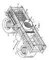
- a reciprocating energy reclaimer with exhaust inlet duct 8 (6" (15 cm) diameter) for receiving heated exhaust gases from a gas furnace or other clean-burning heating unit.
- the exhaust gases pass through porous metal member 20 supported in surrounding frame, which is divided into twelve identical compartments 24 by metal partitions 25; each compartment is 1.5" (3.8 cm) wide, 2 7/8" (7.3 cm) deep, and filled with 1.5 oz. (42 g) of a heat-absorbing, porous metal mesh.
- the mesh is 2.5" (6.4 cm) wide tubular, knitted aluminium, crimped at a 45° angle (available from ACS Industries, Woonsocket, R.I., U.S.A.), and folded in serpentine fashion inside each compartment.
- the exhaust gases transfer their heat to the porous metal member 20, and exit through outlet duct 10 in which there is located exhaust fan 22 driven by motor 23.
- the porous metal member 20 and frame are supported for reciprocating motion by four linear ball bearing assembles 12, two at each end (only two of four show in Figure 1), that ride on linear rods 14.
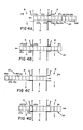
- Movement of the porous member 20 is controlled by gear-drive motor 16, which drives continuous chain 17 around sprockets 18, 19 ( Figures 1 and 3A-3C).
- Cam-follower 30, which is attached to chain 17, drives U channel 32, which is securely fastened to porous metal member 20.
- the porous metal member 20 is moved to one extremity of its traverse ( Figure 3A).
- the cam-follower reaches the extremity of its travel on the chain 17, the cam-follower repositions itself in the U channel to drive the porous member 20 in the opposite direction ( Figures 3B and 3C).
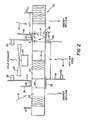
- Reclaiming air blowers 34 direct reclaiming air through ducts 36 (3.5" (8.9 cm) wide) into the porous metal member.
- the reclaiming air ducts 36 are separated from the exhaust outlet duct 10 by a plate 38 (1.0" (2.5 cm) wide) in the plane of the cross section of Figure 2).
- Another plate 28 (1.75" (4.4 cm) wide) in the plane of the cross section of Figure 2) positioned on the opposite side of the porous member 20 acts as an air barrier, and in conjunction with plate 38 accomplishes purging of combustion gases from each compartment prior to energy reclaim.
- the reciprocating member is divided into twelve compartment 24 so that each compartment, as it passes from the exhaust airstream into a reclaim airstream, temporarily occupies the position shown at 26 in Figure 2.
- One side of the compartment straddles the discharge of the reclaim blower and the exhaust duct, while the other side of the compartment is sealed off by air barrier 28.
- purge air P moving from the reclaim blower through the compartment to the exhaust.
- High temperature silicone seals are installed around the porous metal member to prevent leakage between the member and walls 28, 38.
- Exhaust fan 22 simultaneously draws hot exhaust gases into the metal mesh 20 and draws low temperature toxic fumes out the exhaust flue.
- FIGs 4A to 4D illustrate the reciprocating movement of the porous metal member 20.
- the left-most four compartments 24a-24d are being heated by exhaust gases H.
- these compartments have moved out of the path of the exhaust gases H; compartments 24a has already fully passed once through the reclaiming airstream R, compartments 24b and 24c are in the reclaiming airstream, and compartment 24d is in the purging position.
- all four of compartments 24a-24d have made one pass through the reclaiming airstream.
- Figure 4D the same four compartments are making their second pass through the reclaiming airstream.
- All of the compartments, except the middle two, 24f, 24g, make two complete passes through a reclaiming airstream R for each pass through the heated exhaust gases H.
- the middle compartments 24f, 24g make a single pass, but they pause while exposed to the reclaiming air when the porous member 20 reversed direction, thus lengthening their exposure to the reclaiming air.
- Home and industrial combustion heating units typically exhaust to the atmosphere approximately one third of all input energy (BTUs or kJ) fed the heating unit. That lost energy is recovered by passing reciprocating porous metal member 20 through the heated exhaust airstream H, and reclaiming the heat from the porous metal member by passing reclaiming air R through the member.
- a positive exhaust fan 22 is positioned on the discharge side of the exhaust airstream (200 cfm (6.0 m/min) for a 100,000 BTU/hour (29 KW) furnace).
- the front portions of the porous metal member 20 i.e. the portions nearest the feed of heated gases
- the metal member is then subjected to a high volume-high velocity (465 cfm or 13 m/min) r eclaim blower forcing reclaiming air R through the porous member.
- the reclaiming air causes the temperature of the porous member on the exhaust side to be maintained equal to the temperature of the air discharged by the reclaim blower (typically room temperature).
- the reclaim airflow for each reclaim airstream be from 1 to 4 times the exhaust airflow, and most preferably 2 to 2.50 times. Because the majority of compartments 24 are exposed twice to reclaim air for each pass through the exhaust airstream, the ratio of total reclaim airflow to exhaust airflow for these compartments is twice the numbers just given, i.e. preferably from 2 to 8 or most preferably 4 to 5.
- the invention allows up to 95% of the exhaust energy (BTUs or kJ) to be reclaimed from any hot exhaust stack. Installation requires removing a small section of the exhaust duct and securely fastening the remaining ducts to the inlet and outlet ducts 8, 10 of the heat exchanging apparatus.
- the porous metal member is preferably constructed of mesh of such weight and density that the area and thickness of the mesh directly in front of inlet 8 has the capacity to absorb all exhaust heat rising into it.
- Both reclaim blowers should have a capacity of counterflowing sufficient air (460 cfm or 13 m/min) to reduce the metal mesh temperature to the reclaim blower discharge temperature.
- the porous metal member is preferably cycled at 13 cycles per minute. This frequency is based on tests which have shown that 10 cycles/minute should occur for every 50,000 BTU/hour (5.3 ⁇ 104 kJ/h) of energy in the exhaust airstream. For a 200,000 BTU/hour (2.1 x 10⁵ kJ/h) furnace, which sends one third of its energy up the exhaust flue, the frequency is 13 cycles/minute.
- the total weight of the porous metal mesh traversing through the hot gaseous airstream in any given period should equal at least the weight of the air passing through the metal mesh for the same period.
- the weight of the porous mesh traversing through the hot gaseous exhaust airstream be from one to four times (most preferably two to four times) the weight of the hot gaseous exhaust airstream flow for any given period of time.
- the reclaiming apparatus remains inactivated until an on/off heat sensor 50 located in the hot air feed duct 8 is heated to 210°F to 240°F (99° to 116°C) by the furnace turning on (the sensor would preferably be located closer to the furnace than shown in the drawing).
- this sensor detects a temperature of 210°F to 240°F (99° to 116°C)
- motors 16, 23 and both reclaim blowers 34 thus initiating reciprocating movement of porous metal member 20, and positive pumping of the exhaust airstream through porous metal element 20.
- a normally-closed thermal time-delay relay in the circuit to the furnace gas valve is activated, giving the apparatus approximately twenty seconds in which to raise the pressure in the exhaust duct 10, and thereby close the normally-open contacts of a pressure switch 52 connected in series with the gas valve. If the exhaust is not functioning properly (e.g. because fan 22 or motor 23 are not functioning, or flow through porous element 23 is blocked), the circuit to the gas valve would be opened resulting in shutdown of the fur nace as well as the reclaiming apparatus.
- thermal protection switch 54 is of the automatic reset (at 160°F or 71°C) type.
- thermal switch in exhaust motor 23 that will also trip and shut off exhaust motor 23, resulting in shut off or both the gas valve and the reclaiming apparatus. Should any electrical component have a fault, an electrical fuse built into the reciprocating energy reclaiming apparatus would blow, shutting off the gas valve and apparatus.
- a second safety feature on the on/off control is the fact that there would be no pressure to the exhaust pressure switch, and once twenty seconds have past the gas valve would be shut off.
- the described reciprocating energy reclaiming apparatus is simple to fabricate (e.g. it can be made with 18 or 20 gauge sheet metal and electric spotwelding).
- the porous metal member 20 can be quickly removed for access and cleaning; two horseshoe clips on either end of the dual traverse rods 14 are removed, and the rods pulled out through the linear bearings and framework; allowing the porous metal member 20 to drop out easily.
- Cleaning of member 20 should ordinarily not be necessary except at multi-year intervals because of the continuous exposure of the member to counterflowing air currents H, R.
- the monetary savings achievable by installing the unit is between ten to fifteen times the expense of electricity to operate the unit (primarily to operate the reclaim blowers 34).
Landscapes
- Engineering & Computer Science (AREA)
- Mechanical Engineering (AREA)
- General Engineering & Computer Science (AREA)
- Chemical & Material Sciences (AREA)
- Combustion & Propulsion (AREA)
- Physics & Mathematics (AREA)
- Thermal Sciences (AREA)
- Heat-Exchange Devices With Radiators And Conduit Assemblies (AREA)
- Air Supply (AREA)
- Non-Silver Salt Photosensitive Materials And Non-Silver Salt Photography (AREA)
- Compression-Type Refrigeration Machines With Reversible Cycles (AREA)
- Gas Separation By Absorption (AREA)
Claims (10)
- Luft-Luft- Wärme - Tauscher- zur Energie-Rückgewinnung aus einem ersten Luftstrom (H)- durch Übertragung auf eine Regenerativ-Luftströmung (R),
mit- einem Wärme-Absorber- zum Absorbieren von Wärme aus dem ersten Luftstrom (H),- der gekammert ist in Kammern durch Trennwände und- hin-und herbeweglich ist quer zum ersten Luftstrom (H); und- einem Zuluft-Kanal (8) zum- Aufnehmen des ersten Luftstroms (H) und- zu seinem Führen durch den Wärme-Absorber zu- einem Abluft-Kanal (10);
gekennzeichnet durch- ein poröses Element (20),- das den Wärme-Absorber bildet,- einen Abluft-Lüfter (22, Fig. 2)- im Strömungsweg des ersten Luftstroms (H),- um ihn durch das poröse Element(20) abzuziehen,- ein Regenerativ-Luft-Gebläse (34)- zur Abgabe der Regenerativ-Luftströmung (R),- wobei der erste Luftstrom (H) und die Regenerativ-Luftströmung (R) ausreichend in Bewegungsrichtung des porösen Elements (20) beabstandet sind,
so daß strömende Luft zwischen
dem ersten Luftstrom (H) und der Regenerativ-Luftströmung (R) vermieden wird. - Wärme-Tauscher nach Anspruch 1,
gekennzeichnet dadurch, daß- die Regenerativ-Luftströmung (R) so angeordnet und- die Hin-und Herbewegung des porösen Elements (20) ausreichend lang ist,- daß der größte Teil des porösen Elements (20)- zweimal die Regenerativ-Luftströmung (R) durchläuft- bei jedem einzelnen Durchlaufen des ersten Luftstroms (H). - Wärme-Tauscher nach Anspruch 1 oder 2,
gekennzeichnet dadurch, daß- die Bewegung des porösen Elements (20)- auf einer Geraden erfolgt. - Wärme-Tauscher nach einem der vorhergehenden Ansprüche,
gekennzeichnet dadurch, daß- die Regenerativ-Luftströmung (R)- entgegengesetzt zum ersten Luftstrom (H) strömt. - Wärme-Tauscher nach einem der vorhergehenden Ansprüche,
gekennzeichnet durch- eine Einrichtung zum Hin- und Herbewegen des porösen Elements (20)- mit- einer oder mehreren Stangen (14),- die in Richtung der Hin-und Herbewegung verlaufen, und- einem linearen Lager (12),- das das poröse Element (20) auf den Stäben (14) lagert, und- das das poröse Element (20) reibungs-und verschleißarm lagert. - Wärme-Tauscher nach einem der vorhergehenden Ansprüche,
gekennzeichnet dadurch, daß- das poröse Element besitzt- ein Metall-Gitter (20),- das ausreichend porös ist für den Durchtritt des ersten Luftstroms (H). - Wärme-Tauscher nach einem der vorhergehenden Ansprüche,
gekennzeichnet dadurch, daß- die Regenerativ-Luftströmung (R) so angeordnet und- die Hin-und Herbewegung des porösen Elements (20) ausreichend lang ist,- daß bei jedem Bewegungs-Takt des porösen Elements (20)- der größte Teil des porösen Elements (20)- eine längere Verweildauer- in der Regenerativ-Luftströmung (R) als im ersten Luftstrom (H) hat. - Wärme-Tauscher nach einem der vorhergehenden Ansprüche,- wobei- der erste Luftstrom (H)- verunreinigte Gasegekennzeichnet durch
wie Brenngase aus einer Verbrennungs-Heizung enthält,- eine Reinigungs-Einrichtung (25,28,38, Fig. 2)- zum Führen einer Reinigungs-Luftstroms (P) durch Teile des porösen Elements (20),- die aus dem Abluft-Strom austreten,- so daß die verunreingten Gase nicht in die Regenerativ-Luftströmung (R) eintreten. - Wärme-Tauscher nach Anspruch 8,
gekennzeichnet dadurch, daß- die Reinigungs-Einrichtung (25,28,38, Fig. 2) besitzt- eine Einrichtung zum Führen des Reinigungs-Luftstroms (P) nicht verunreinigt- auf einem Strömungsweg,- der durch die austretenden Teile des porösen Elements (20) verläuft und- in den ersten Luftstrom (H) an der Abluft-Seite des porösen Elements (20) mündet. - Wärme-Tauscher nach einem der Ansprüche 6 - 9,
gekennzeichnet dadurch, daß- das Gesamtgewicht des porösen Metall-Gitters (20),- das den ersten Luftstrom (H) durchläuft,- gleich dem oder größer, vorzugsweise zwei-bis vierfach, als das Gewicht des ersten Luftstroms (H) für dieselbe Periode ist.
Priority Applications (1)
| Application Number | Priority Date | Filing Date | Title |
|---|---|---|---|
| AT87308093T ATE80219T1 (de) | 1986-09-12 | 1987-09-14 | Sich hin- und herbewegender waermeaustauscher. |
Applications Claiming Priority (2)
| Application Number | Priority Date | Filing Date | Title |
|---|---|---|---|
| US06/907,049 US4754806A (en) | 1986-09-12 | 1986-09-12 | Reciprocating heat exchanger |
| US907049 | 1986-09-12 |
Publications (2)
| Publication Number | Publication Date |
|---|---|
| EP0260907A1 EP0260907A1 (de) | 1988-03-23 |
| EP0260907B1 true EP0260907B1 (de) | 1992-09-02 |
Family
ID=25423436
Family Applications (1)
| Application Number | Title | Priority Date | Filing Date |
|---|---|---|---|
| EP87308093A Expired - Lifetime EP0260907B1 (de) | 1986-09-12 | 1987-09-14 | Sich hin- und herbewegender Wärmeaustauscher |
Country Status (8)
| Country | Link |
|---|---|
| US (1) | US4754806A (de) |
| EP (1) | EP0260907B1 (de) |
| JP (1) | JPS63140289A (de) |
| AT (1) | ATE80219T1 (de) |
| AU (1) | AU7779387A (de) |
| CA (1) | CA1297094C (de) |
| DE (1) | DE3781487T2 (de) |
| ES (1) | ES2035074T3 (de) |
Families Citing this family (22)
| Publication number | Priority date | Publication date | Assignee | Title |
|---|---|---|---|---|
| US5184600A (en) * | 1989-06-08 | 1993-02-09 | Astle Jr William B | Regulating the humidity of a heated space by varying the amount of moisture transferred from the combustion gases |
| US5005556A (en) * | 1989-06-08 | 1991-04-09 | Astle Jr William B | Efficient gas hot-air furnace and heating process |
| GB9027184D0 (en) * | 1990-12-14 | 1991-02-06 | Ettinger George M | Heat transport apparatus |
| JP2627373B2 (ja) * | 1991-07-08 | 1997-07-02 | 金井 宏之 | 高強度極細金属線 |
| US5134945A (en) * | 1992-01-06 | 1992-08-04 | Reimlinger Richard G | Regenerative thermal oxidizer with gate manifold system |
| US5273106A (en) * | 1992-07-21 | 1993-12-28 | Mechanical Technology Inc. | Self-defrosting recuperative air-to-air heat exchanger |
| WO1994010509A1 (en) * | 1992-10-27 | 1994-05-11 | Astle William B Jr | Humidity control: moisture transfer from combustion gases |
| US5309851A (en) * | 1993-07-15 | 1994-05-10 | Reimlinger Richard G | Regenerative thermal oxidizer with gate manifold pressurization |
| US5293827A (en) * | 1993-07-15 | 1994-03-15 | Nester James L | Regenerative thermal oxidizer with gate manifolds including purges |
| US5562089A (en) * | 1994-06-07 | 1996-10-08 | Astle, Jr; William B. | Heating with a moving heat sink |
| GB2296966A (en) * | 1995-01-06 | 1996-07-17 | Andrew Bell | Regenerative heat exchanger with reciprocating elements |
| US6257317B1 (en) | 1997-07-11 | 2001-07-10 | Elastek | Integrated heat recovery ventilator-hepa filter |
| US6289974B1 (en) | 1997-07-11 | 2001-09-18 | Elastek, Inc. | Integrated heat recovery ventilator HEPA filter using a HEPA filter material regenerative heat exchanger |
| US7150314B2 (en) * | 2001-09-17 | 2006-12-19 | American Standard International Inc. | Dual exhaust energy recovery system |
| DE10321646A1 (de) * | 2002-06-03 | 2004-07-15 | Rubitherm Gmbh | Verfahren zur Wärme- und Kälteversorgung eines Raumes und Gebäude mit einer Mehrzahl mit einer Mehrzahl von Räumen |
| US20060054301A1 (en) * | 2004-02-19 | 2006-03-16 | Mcray Richard F | Variable area mass or area and mass species transfer device and method |
| KR100584306B1 (ko) * | 2004-05-21 | 2006-05-26 | 엘지전자 주식회사 | 가습 및 제습장치 |
| JP2009047407A (ja) * | 2007-07-23 | 2009-03-05 | Panasonic Corp | 調湿装置とその調湿装置を備えた空気調和機 |
| US8973649B2 (en) * | 2008-12-23 | 2015-03-10 | Tai-Her Yang | Heat exchange apparatus with a rotating disk and automatic control of heat exchange between two fluid streams by modulation of disk rotating speed and/or flow rate |
| US8794601B2 (en) | 2010-12-16 | 2014-08-05 | Carrier Corporation | Humidifier |
| US8978639B2 (en) * | 2011-10-14 | 2015-03-17 | Hearth & Home Technologies, Inc. | Secondary room air heat exchanger and method of heating secondary room air |
| CN117537612A (zh) * | 2023-01-31 | 2024-02-09 | 宜兴爱宜艺术陶瓷有限公司 | 一种紫砂壶烧制炉窑及工艺 |
Family Cites Families (3)
| Publication number | Priority date | Publication date | Assignee | Title |
|---|---|---|---|---|
| GB220867A (en) * | 1923-12-13 | 1924-08-28 | Henry Harold Perry | Improvements in regenerators for air and gases |
| DE1108371B (de) * | 1958-02-21 | 1961-06-08 | Schmidt Sche Heissdampf | Regenerativ-Luft- oder Gasvorwaermer, dessen Waermespeichermassen parallel zueinander und quer durch Kanaele verfahrbar angeordnet sind |
| US3823766A (en) * | 1971-04-22 | 1974-07-16 | Garrett Corp | Dynamic regenerative heat exchanger |
-
1986
- 1986-09-12 US US06/907,049 patent/US4754806A/en not_active Expired - Fee Related
-
1987
- 1987-09-03 AU AU77793/87A patent/AU7779387A/en not_active Abandoned
- 1987-09-10 CA CA000546547A patent/CA1297094C/en not_active Expired - Lifetime
- 1987-09-11 JP JP62228220A patent/JPS63140289A/ja active Pending
- 1987-09-14 AT AT87308093T patent/ATE80219T1/de not_active IP Right Cessation
- 1987-09-14 DE DE8787308093T patent/DE3781487T2/de not_active Expired - Fee Related
- 1987-09-14 EP EP87308093A patent/EP0260907B1/de not_active Expired - Lifetime
- 1987-09-14 ES ES198787308093T patent/ES2035074T3/es not_active Expired - Lifetime
Non-Patent Citations (1)
| Title |
|---|
| Recknagel-Sprenger-Hönmann, "Taschenbuch für Heizung und Klimatechnik", 63.Ausgabe 1985, page 1136 * |
Also Published As
| Publication number | Publication date |
|---|---|
| US4754806A (en) | 1988-07-05 |
| ES2035074T3 (es) | 1993-04-16 |
| EP0260907A1 (de) | 1988-03-23 |
| DE3781487T2 (de) | 1993-04-08 |
| ATE80219T1 (de) | 1992-09-15 |
| DE3781487D1 (de) | 1992-10-08 |
| AU7779387A (en) | 1988-03-17 |
| CA1297094C (en) | 1992-03-10 |
| JPS63140289A (ja) | 1988-06-11 |
Similar Documents
| Publication | Publication Date | Title |
|---|---|---|
| EP0260907B1 (de) | Sich hin- und herbewegender Wärmeaustauscher | |
| US5003961A (en) | Apparatus for ultra high energy efficient heating, cooling and dehumidifying of air | |
| AU742412B2 (en) | Web dryer with fully integrated regenerative heat source | |
| US4650414A (en) | Regenerative heat exchanger apparatus and method of operating the same | |
| US4384850A (en) | Recirculating air heater | |
| JP5408629B2 (ja) | 空気予熱器及び空気予熱器内におけるファウリングを減少せしめる方法 | |
| CA2432109C (en) | Web dryer with fully integrated regenerative heat source and control thereof | |
| RU2119127C1 (ru) | Регенеративный теплообменник и способ его эксплуатации | |
| CA1061303A (en) | Heat recovery apparatus | |
| AU2002219933A1 (en) | Web dryer with fully integrated regenerative heat source and control thereof | |
| EP0343938B1 (de) | Raumheizungs- und -lüftungssystem für Gebäude | |
| US4470806A (en) | Regenerative incinerators | |
| US3634026A (en) | Apparatus and method thermal regenerative gas processing | |
| CN208920096U (zh) | 一种吊篮蓄热式空气预热器 | |
| SU1083925A3 (ru) | Устройство дл термообработки агрегатного материала газовым потоком | |
| US3764259A (en) | Gas treating apparatus | |
| JP3007575B2 (ja) | 白煙防止用空気加熱装置 | |
| NL8201275A (nl) | Werkwijze en inrichting voor het opwekken van warmte. | |
| CN108930976A (zh) | 一种吊篮蓄热式空气预热器 | |
| EP3770542B1 (de) | Wärmerückgewinnungseinheit | |
| CN215327679U (zh) | 一种封闭式干燥箱 | |
| JP3037483U (ja) | 白煙防止用空気加熱装置 | |
| CA1103657A (en) | High energy saving heat exchanger for furnaces | |
| JPH10212529A (ja) | 金属帯の焼鈍炉用熱交換器 | |
| Ee et al. | Heat exchange appartus |
Legal Events
| Date | Code | Title | Description |
|---|---|---|---|
| PUAI | Public reference made under article 153(3) epc to a published international application that has entered the european phase |
Free format text: ORIGINAL CODE: 0009012 |
|
| AK | Designated contracting states |
Kind code of ref document: A1 Designated state(s): AT BE CH DE ES FR GB GR IT LI LU NL SE |
|
| 17P | Request for examination filed |
Effective date: 19880921 |
|
| 17Q | First examination report despatched |
Effective date: 19890706 |
|
| GRAA | (expected) grant |
Free format text: ORIGINAL CODE: 0009210 |
|
| AK | Designated contracting states |
Kind code of ref document: B1 Designated state(s): AT BE CH DE ES FR GB GR IT LI LU NL SE |
|
| PG25 | Lapsed in a contracting state [announced via postgrant information from national office to epo] |
Ref country code: SE Effective date: 19920902 Ref country code: NL Effective date: 19920902 Ref country code: LI Effective date: 19920902 Ref country code: GR Free format text: LAPSE BECAUSE OF FAILURE TO SUBMIT A TRANSLATION OF THE DESCRIPTION OR TO PAY THE FEE WITHIN THE PRESCRIBED TIME-LIMIT Effective date: 19920902 Ref country code: CH Effective date: 19920902 Ref country code: BE Effective date: 19920902 Ref country code: AT Effective date: 19920902 |
|
| REF | Corresponds to: |
Ref document number: 80219 Country of ref document: AT Date of ref document: 19920915 Kind code of ref document: T |
|
| PG25 | Lapsed in a contracting state [announced via postgrant information from national office to epo] |
Ref country code: LU Free format text: LAPSE BECAUSE OF NON-PAYMENT OF DUE FEES Effective date: 19920930 |
|
| REF | Corresponds to: |
Ref document number: 3781487 Country of ref document: DE Date of ref document: 19921008 |
|
| ITF | It: translation for a ep patent filed | ||
| REG | Reference to a national code |
Ref country code: CH Ref legal event code: PL |
|
| ET | Fr: translation filed | ||
| NLV1 | Nl: lapsed or annulled due to failure to fulfill the requirements of art. 29p and 29m of the patents act | ||
| REG | Reference to a national code |
Ref country code: ES Ref legal event code: FG2A Ref document number: 2035074 Country of ref document: ES Kind code of ref document: T3 |
|
| PLBE | No opposition filed within time limit |
Free format text: ORIGINAL CODE: 0009261 |
|
| STAA | Information on the status of an ep patent application or granted ep patent |
Free format text: STATUS: NO OPPOSITION FILED WITHIN TIME LIMIT |
|
| 26N | No opposition filed | ||
| ITTA | It: last paid annual fee | ||
| PGFP | Annual fee paid to national office [announced via postgrant information from national office to epo] |
Ref country code: GB Payment date: 19940225 Year of fee payment: 7 |
|
| PGFP | Annual fee paid to national office [announced via postgrant information from national office to epo] |
Ref country code: ES Payment date: 19940311 Year of fee payment: 7 |
|
| PGFP | Annual fee paid to national office [announced via postgrant information from national office to epo] |
Ref country code: FR Payment date: 19940315 Year of fee payment: 7 |
|
| PGFP | Annual fee paid to national office [announced via postgrant information from national office to epo] |
Ref country code: DE Payment date: 19940324 Year of fee payment: 7 |
|
| PG25 | Lapsed in a contracting state [announced via postgrant information from national office to epo] |
Ref country code: GB Effective date: 19940914 |
|
| PG25 | Lapsed in a contracting state [announced via postgrant information from national office to epo] |
Ref country code: ES Free format text: LAPSE BECAUSE OF EXPIRATION OF PROTECTION Effective date: 19940915 |
|
| GBPC | Gb: european patent ceased through non-payment of renewal fee |
Effective date: 19940914 |
|
| PG25 | Lapsed in a contracting state [announced via postgrant information from national office to epo] |
Ref country code: FR Effective date: 19950531 |
|
| PG25 | Lapsed in a contracting state [announced via postgrant information from national office to epo] |
Ref country code: DE Effective date: 19950601 |
|
| REG | Reference to a national code |
Ref country code: FR Ref legal event code: ST |
|
| REG | Reference to a national code |
Ref country code: ES Ref legal event code: FD2A Effective date: 20010201 |
|
| PG25 | Lapsed in a contracting state [announced via postgrant information from national office to epo] |
Ref country code: IT Free format text: LAPSE BECAUSE OF NON-PAYMENT OF DUE FEES Effective date: 20050914 |