EP0260907A1 - Sich hin- und herbewegender Wärmeaustauscher - Google Patents
Sich hin- und herbewegender Wärmeaustauscher Download PDFInfo
- Publication number
- EP0260907A1 EP0260907A1 EP87308093A EP87308093A EP0260907A1 EP 0260907 A1 EP0260907 A1 EP 0260907A1 EP 87308093 A EP87308093 A EP 87308093A EP 87308093 A EP87308093 A EP 87308093A EP 0260907 A1 EP0260907 A1 EP 0260907A1
- Authority
- EP
- European Patent Office
- Prior art keywords
- airstream
- porous element
- reclaiming
- exhaust
- porous
- Prior art date
- Legal status (The legal status is an assumption and is not a legal conclusion. Google has not performed a legal analysis and makes no representation as to the accuracy of the status listed.)
- Granted
Links
- 229910052751 metal Inorganic materials 0.000 claims abstract description 38
- 239000002184 metal Substances 0.000 claims abstract description 38
- 239000007789 gas Substances 0.000 claims description 35
- 238000010926 purge Methods 0.000 claims description 15
- 238000002485 combustion reaction Methods 0.000 claims description 8
- 238000010438 heat treatment Methods 0.000 claims description 7
- 239000000567 combustion gas Substances 0.000 claims description 4
- 239000003570 air Substances 0.000 description 38
- 238000011084 recovery Methods 0.000 description 9
- 230000004888 barrier function Effects 0.000 description 6
- 238000004140 cleaning Methods 0.000 description 2
- 238000009434 installation Methods 0.000 description 2
- 241000894006 Bacteria Species 0.000 description 1
- 239000011358 absorbing material Substances 0.000 description 1
- WYTGDNHDOZPMIW-RCBQFDQVSA-N alstonine Natural products C1=CC2=C3C=CC=CC3=NC2=C2N1C[C@H]1[C@H](C)OC=C(C(=O)OC)[C@H]1C2 WYTGDNHDOZPMIW-RCBQFDQVSA-N 0.000 description 1
- 239000004411 aluminium Substances 0.000 description 1
- 229910052782 aluminium Inorganic materials 0.000 description 1
- XAGFODPZIPBFFR-UHFFFAOYSA-N aluminium Chemical compound [Al] XAGFODPZIPBFFR-UHFFFAOYSA-N 0.000 description 1
- 239000012080 ambient air Substances 0.000 description 1
- 230000001143 conditioned effect Effects 0.000 description 1
- 230000009977 dual effect Effects 0.000 description 1
- 230000005611 electricity Effects 0.000 description 1
- 238000004134 energy conservation Methods 0.000 description 1
- 239000003517 fume Substances 0.000 description 1
- 230000000977 initiatory effect Effects 0.000 description 1
- VNWKTOKETHGBQD-UHFFFAOYSA-N methane Natural products C VNWKTOKETHGBQD-UHFFFAOYSA-N 0.000 description 1
- 238000005192 partition Methods 0.000 description 1
- 229920001296 polysiloxane Polymers 0.000 description 1
- 238000005086 pumping Methods 0.000 description 1
- 230000000630 rising effect Effects 0.000 description 1
- 231100000331 toxic Toxicity 0.000 description 1
- 230000002588 toxic effect Effects 0.000 description 1
Images


Classifications
-
- F—MECHANICAL ENGINEERING; LIGHTING; HEATING; WEAPONS; BLASTING
- F23—COMBUSTION APPARATUS; COMBUSTION PROCESSES
- F23L—SUPPLYING AIR OR NON-COMBUSTIBLE LIQUIDS OR GASES TO COMBUSTION APPARATUS IN GENERAL ; VALVES OR DAMPERS SPECIALLY ADAPTED FOR CONTROLLING AIR SUPPLY OR DRAUGHT IN COMBUSTION APPARATUS; INDUCING DRAUGHT IN COMBUSTION APPARATUS; TOPS FOR CHIMNEYS OR VENTILATING SHAFTS; TERMINALS FOR FLUES
- F23L15/00—Heating of air supplied for combustion
- F23L15/02—Arrangements of regenerators
-
- F—MECHANICAL ENGINEERING; LIGHTING; HEATING; WEAPONS; BLASTING
- F28—HEAT EXCHANGE IN GENERAL
- F28D—HEAT-EXCHANGE APPARATUS, NOT PROVIDED FOR IN ANOTHER SUBCLASS, IN WHICH THE HEAT-EXCHANGE MEDIA DO NOT COME INTO DIRECT CONTACT
- F28D19/00—Regenerative heat-exchange apparatus in which the intermediate heat-transfer medium or body is moved successively into contact with each heat-exchange medium
- F28D19/04—Regenerative heat-exchange apparatus in which the intermediate heat-transfer medium or body is moved successively into contact with each heat-exchange medium using rigid bodies, e.g. mounted on a movable carrier
-
- Y—GENERAL TAGGING OF NEW TECHNOLOGICAL DEVELOPMENTS; GENERAL TAGGING OF CROSS-SECTIONAL TECHNOLOGIES SPANNING OVER SEVERAL SECTIONS OF THE IPC; TECHNICAL SUBJECTS COVERED BY FORMER USPC CROSS-REFERENCE ART COLLECTIONS [XRACs] AND DIGESTS
- Y02—TECHNOLOGIES OR APPLICATIONS FOR MITIGATION OR ADAPTATION AGAINST CLIMATE CHANGE
- Y02E—REDUCTION OF GREENHOUSE GAS [GHG] EMISSIONS, RELATED TO ENERGY GENERATION, TRANSMISSION OR DISTRIBUTION
- Y02E20/00—Combustion technologies with mitigation potential
- Y02E20/34—Indirect CO2mitigation, i.e. by acting on non CO2directly related matters of the process, e.g. pre-heating or heat recovery
-
- Y—GENERAL TAGGING OF NEW TECHNOLOGICAL DEVELOPMENTS; GENERAL TAGGING OF CROSS-SECTIONAL TECHNOLOGIES SPANNING OVER SEVERAL SECTIONS OF THE IPC; TECHNICAL SUBJECTS COVERED BY FORMER USPC CROSS-REFERENCE ART COLLECTIONS [XRACs] AND DIGESTS
- Y10—TECHNICAL SUBJECTS COVERED BY FORMER USPC
- Y10S—TECHNICAL SUBJECTS COVERED BY FORMER USPC CROSS-REFERENCE ART COLLECTIONS [XRACs] AND DIGESTS
- Y10S165/00—Heat exchange
- Y10S165/009—Heat exchange having a solid heat storage mass for absorbing heat from one fluid and releasing it to another, i.e. regenerator
- Y10S165/013—Movable heat storage mass with enclosure
- Y10S165/014—Reciprocated linearly
-
- Y—GENERAL TAGGING OF NEW TECHNOLOGICAL DEVELOPMENTS; GENERAL TAGGING OF CROSS-SECTIONAL TECHNOLOGIES SPANNING OVER SEVERAL SECTIONS OF THE IPC; TECHNICAL SUBJECTS COVERED BY FORMER USPC CROSS-REFERENCE ART COLLECTIONS [XRACs] AND DIGESTS
- Y10—TECHNICAL SUBJECTS COVERED BY FORMER USPC
- Y10S—TECHNICAL SUBJECTS COVERED BY FORMER USPC CROSS-REFERENCE ART COLLECTIONS [XRACs] AND DIGESTS
- Y10S165/00—Heat exchange
- Y10S165/901—Heat savers
Definitions
- This invention relates to air-to-air heat exchangers for reclaiming energy from, for example, the air exhausted from heated or cooled buildings.
- the exhaust from a typical combustion furnace or other heating unit may contain of the order of one third of the energy supplied to the furnace; thus, tremendous losses of energy occur unless energy is reclaimed from the exhaust airstream.
- a more effective air-to-air heat exchanger to reclaim more of the energy from the exhaust air.
- a pie-shaped purging section at the boundary between the exhaust airstream and the incoming airstream has been employed, in combination with pie-shaped compartments in the wheel, to redirect back through the heat recovery wheel and into the outgoing exhaust incoming air that flows into the pie-shaped section.
- the invention features a heat exchanger for reclaiming energy from a first airstream, which in some embodiments will be an exhaust airstream.
- the exchanger includes a porous metal element suitable for absorbing heat from the exhaust airstream, means for reciprocally moving the porous element back and forth transversely to the exhaust airstream, an inlet duct for receiving the exhaust airstream and directing it through the porous element to an outlet duct, reclaiming air blower means for delivering two heat-reclaiming airstreams through the porous metal element, one on either side of the exhaust airstream, and an air exhaust fan in the path of said exhaust airstream for drawing said airstream through said porous element.
- the heat reclaiming airstreams are so located and the reciprocal movement of the porous element is sufficiently long that most portions of the porous element pass twice through a reclaiming airstream for each single pass through the exhaust airstream.
- An exhaust fan in the exhaust outlet duct draws the exhaust airstream through the porous element.
- the porous element is compartmentalised by transverse barriers, and means are provided for purging each compartment of undesirable gases (e.g. products of combustion) in the exhaust airstream as each compartment passes out of the exhaust airstream.
- the porous element is supported on linear bearings and rods extending along the direction of reciprocal movement. The invention provides improved energy recovery in a compact, easily manufactured, easily serviced device.
- the improvements make energy recovery from exhaust gases suitable for applications for which prior exhaust gas reclaimers were impractical, e.g. on the exhaust of overhead heaters in industrial buildings, and on home furnaces. Alignment and balancing difficulties that can result with the heat recovery wheel are avoided.
- the invention can be installed in any orientation (although power is minimised if the support rods are horizontal); by contrast, the heat rec overy wheel is installed in a vertical orientation.
- the invention also provides better uniformity of airflow through the porous member because the compartments can be rectangular; in the heat recovery wheel, the compartments are pie shaped, and flow is limited through the narrow portions of the compartments near the axis of rotation.
- the invention has application in summer as well as winter; energy can be reclaimed from cooled air exhausted from air conditioned buildings.
- the invention also has application to exhaust airstreams from hospital environments where it is necessary to purge bacteria from the exhaust.
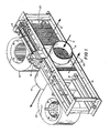
- a reciprocating energy reclaimer with exhaust inlet duct 8 (6" (15 cm) diameter) for receiving heated exhaust gases from a gas furnace or other clean-burning heating unit.
- the exhaust gases pass through porous metal member 20 supported in surrounding frame, which is divided into twelve identical compartments 24 by metal partitions 25; each compartment is 1.5" (3.8 cm) wide, 2 7/8" (7.3 cm) deep, and filled with 1.5 oz. (42 g) of a heat-absorbing, porous metal mesh.
- the mesh is 2.5" (6.4 cm) wide tubular, knitted aluminium, crimped at a 45° angle (available from ACS Industries, Woonsocket, R.I., U.S.A.), and folded in serpentine fashion inside each compartment.
- the exhaust gases transfer their heat to the porous metal member 20, and exit through outlet duct 10 in which there is located exhaust fan 22 driven by motor 23.
- the porous metal member 20 and frame are supported for reciprocating motion by four linear ball bearing assembles 12, two at each end (only two of four show in Figure 1), that ride on linear rods 14.
- Movement of the porous member 20 is controlled by gear-drive motor 16, which drives continuous chain 17 around sprockets 18, 19 ( Figures 1 and 3A-3C).
- Cam-follower 30, which is attached to chain 17, drives U channel 32, which is securely fastened to porous metal member 20.
- the porous metal member 20 is moved to one extremity of its traverse ( Figure 3A).
- the cam-follower reaches the extremity of its travel on the chain 17, the cam-follower repositions itself in the U channel to drive the porous member 20 in the opposite direction ( Figures 3B and 3C).
- Reclaiming air blowers 34 direct reclaiming air through ducts 36 (3.5" (8.9 cm) wide) into the porous metal member.
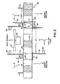
- the reclaiming air ducts 36 are separated from the exhaust outlet duct 10 by a plate 38 (1.0" (2.5 cm) wide) in the plane of the cross section of Figure 2).
- Another plate 28 (1.75" (4.4 cm) wide) in the plane of the cross section of Figure 2) positioned on the opposite side of the porous member 20 acts as an air barrier, and in conjunction with plate 38 accomplishes purging of combustion gases from each compartment prior to energy reclaim.
- the reciprocating member is divided into twelve compartment 24 so that each compartment, as it passes from the exhaust airstream into a reclaim airstream, temporarily occupies the position shown at 26 in Figure 2.
- One side of the compartment straddles the discharge of the reclaim blower and the exhaust duct, while the other side of the compartment is sealed off by air barrier 28.
- purge air P moving from the reclaim blower through the compartment to the exhaust.
- High temperature silicone seals are installed around the porous metal member to prevent leakage between the member and walls 28, 38.
- Exhaust fan 22 simultaneously draws hot exhaust gases into the metal mesh 20 and draws low temperature toxic fumes out the exhaust flue.
- FIGs 4A to 4D illustrate the reciprocating movement of the porous metal member 20.
- the left-most four compartments 24a-24d are being heated by exhaust gases H.
- these compartments have moved out of the path of the exhaust gases H; compartments 24a has already fully passed once through the reclaiming airstream R, compartments 24b and 24c are in the reclaiming airstream, and compartment 24d is in the purging position.
- all four of compartments 24a-24d have made one pass through the reclaiming airstream.
- Figure 4D the same four compartments are making their second pass through the reclaiming airstream.
- All of the compartments, except the middle two, 24f, 24g, make two complete passes through a reclaiming airstream R for each pass through the heated exhaust gases H.
- the middle compartments 24f, 24g make a single pass, but they pause while exposed to the reclaiming air when the porous member 20 reversed direction, thus lengthening their exposure to the reclaiming air.
- Home and industrial combustion heating units typically exhaust to the atmosphere approximately one third of all input energy (BTUs or kJ) fed the heating unit. That lost energy is recovered by passing reciprocating porous metal member 20 through the heated exhaust airstream H, and reclaiming the heat from the porous metal member by passing reclaiming air R through the member.
- a positive exhaust fan 22 is positioned on the discharge side of the exhaust airstream (200 cfm (6.0 m/min) for a 100,000 BTU/hour (29 KW) furnace).
- the front portions of the porous metal member 20 i.e. the portions nearest the feed of heated gases
- the metal member is then subjected to a high volume-high velocity (465 cfm or 13 m/min) r eclaim blower forcing reclaiming air R through the porous member.
- the reclaiming air causes the temperature of the porous member on the exhaust side to be maintained equal to the temperature of the air discharged by the reclaim blower (typically room temperature).
- the reclaim airflow for each reclaim airstream be from 1 to 4 times the exhaust airflow, and most preferably 2 to 2.50 times. Because the majority of compartments 24 are exposed twice to reclaim air for each pass through the exhaust airstream, the ratio of total reclaim airflow to exhaust airflow for these compartments is twice the numbers just given, i.e. preferably from 2 to 8 or most preferably 4 to 5.
- the invention allows up to 95% of the exhaust energy (BTUs or kJ) to be reclaimed from any hot exhaust stack. Installation requires removing a small section of the exhaust duct and securely fastening the remaining ducts to the inlet and outlet ducts 8, 10 of the heat exchanging apparatus.
- the porous metal member is preferably constructed of mesh of such weight and density that the area and thickness of the mesh directly in front of inlet 8 has the capacity to absorb all exhaust heat rising into it.
- Both reclaim blowers should have a capacity of counterflowing sufficient air (460 cfm or 13 m/min) to reduce the metal mesh temperature to the reclaim blower discharge temperature.
- the porous metal member is preferably cycled at 13 cycles per minute. This frequency is based on tests which have shown that 10 cycles/minute should occur for every 50,000 BTU/hour (5.3 ⁇ 104 kJ/h) of energy in the exhaust airstream. For a 200,000 BTU/hour (2.1 x 10⁵ kJ/h) furnace, which sends one third of its energy up the exhaust flue, the frequency is 13 cycles/minute.
- the total weight of the porous metal mesh traversing through the hot gaseous airstream in any given period should equal at least the weight of the air passing through the metal mesh for the same period.
- the weight of the porous mesh traversing through the hot gaseous exhaust airstream be from one to four times (most preferably two to four times) the weight of the hot gaseous exhaust airstream flow for any given period of time.
- the reclaiming apparatus remains inactivated until an on/off heat sensor 50 located in the hot air feed duct 8 is heated to 210°F to 240°F (99° to 116°C) by the furnace turning on (the sensor would preferably be located closer to the furnace than shown in the drawing).
- this sensor detects a temperature of 210°F to 240°F (99° to 116°C)
- motors 16, 23 and both reclaim blowers 34 thus initiating reciprocating movement of porous metal member 20, and positive pumping of the exhaust airstream through porous metal element 20.
- a normally-closed thermal time-delay relay in the circuit to the furnace gas valve is activated, giving the apparatus approximately twenty seconds in which to raise the pressure in the exhaust duct 10, and thereby close the normally-open contacts of a pressure switch 52 connected in series with the gas valve. If the exhaust is not functioning properly (e.g. because fan 22 or motor 23 are not functioning, or flow through porous element 23 is blocked), the circuit to the gas valve would be opened resulting in shutdown of the fur nace as well as the reclaiming apparatus.
- thermal protection switch 54 is of the automatic reset (at 160°F or 71°C) type.
- thermal switch in exhaust motor 23 that will also trip and shut off exhaust motor 23, resulting in shut off or both the gas valve and the reclaiming apparatus. Should any electrical component have a fault, an electrical fuse built into the reciprocating energy reclaiming apparatus would blow, shutting off the gas valve and apparatus.
- a second safety feature on the on/off control is the fact that there would be no pressure to the exhaust pressure switch, and once twenty seconds have past the gas valve would be shut off.
- the described reciprocating energy reclaiming apparatus is simple to fabricate (e.g. it can be made with 18 or 20 gauge sheet metal and electric spotwelding).
- the porous metal member 20 can be quickly removed for access and cleaning; two horseshoe clips on either end of the dual traverse rods 14 are removed, and the rods pulled out through the linear bearings and framework; allowing the porous metal member 20 to drop out easily.
- Cleaning of member 20 should ordinarily not be necessary except at multi-year intervals because of the continuous exposure of the member to counterflowing air currents H, R.
Landscapes
- Engineering & Computer Science (AREA)
- Mechanical Engineering (AREA)
- General Engineering & Computer Science (AREA)
- Chemical & Material Sciences (AREA)
- Combustion & Propulsion (AREA)
- Physics & Mathematics (AREA)
- Thermal Sciences (AREA)
- Heat-Exchange Devices With Radiators And Conduit Assemblies (AREA)
- Air Supply (AREA)
- Non-Silver Salt Photosensitive Materials And Non-Silver Salt Photography (AREA)
- Compression-Type Refrigeration Machines With Reversible Cycles (AREA)
- Gas Separation By Absorption (AREA)
Priority Applications (1)
| Application Number | Priority Date | Filing Date | Title |
|---|---|---|---|
| AT87308093T ATE80219T1 (de) | 1986-09-12 | 1987-09-14 | Sich hin- und herbewegender waermeaustauscher. |
Applications Claiming Priority (2)
| Application Number | Priority Date | Filing Date | Title |
|---|---|---|---|
| US06/907,049 US4754806A (en) | 1986-09-12 | 1986-09-12 | Reciprocating heat exchanger |
| US907049 | 1986-09-12 |
Publications (2)
| Publication Number | Publication Date |
|---|---|
| EP0260907A1 true EP0260907A1 (de) | 1988-03-23 |
| EP0260907B1 EP0260907B1 (de) | 1992-09-02 |
Family
ID=25423436
Family Applications (1)
| Application Number | Title | Priority Date | Filing Date |
|---|---|---|---|
| EP87308093A Expired - Lifetime EP0260907B1 (de) | 1986-09-12 | 1987-09-14 | Sich hin- und herbewegender Wärmeaustauscher |
Country Status (8)
| Country | Link |
|---|---|
| US (1) | US4754806A (de) |
| EP (1) | EP0260907B1 (de) |
| JP (1) | JPS63140289A (de) |
| AT (1) | ATE80219T1 (de) |
| AU (1) | AU7779387A (de) |
| CA (1) | CA1297094C (de) |
| DE (1) | DE3781487T2 (de) |
| ES (1) | ES2035074T3 (de) |
Cited By (4)
| Publication number | Priority date | Publication date | Assignee | Title |
|---|---|---|---|---|
| GB2252817B (en) * | 1990-12-14 | 1995-05-10 | George Michael Ettinger | Heat transport systems |
| GB2296966A (en) * | 1995-01-06 | 1996-07-17 | Andrew Bell | Regenerative heat exchanger with reciprocating elements |
| WO2005083344A3 (en) * | 2004-02-19 | 2006-01-26 | Wilson Turbopower Inc | Variable area or mass or area and mass species transfer device and method |
| EP1598602A3 (de) * | 2004-05-21 | 2006-05-31 | LG Electronics Inc. | Anordnung zum Regeln von Feuchte mittels flüssigen Trocknungsmittels |
Families Citing this family (18)
| Publication number | Priority date | Publication date | Assignee | Title |
|---|---|---|---|---|
| US5184600A (en) * | 1989-06-08 | 1993-02-09 | Astle Jr William B | Regulating the humidity of a heated space by varying the amount of moisture transferred from the combustion gases |
| US5005556A (en) * | 1989-06-08 | 1991-04-09 | Astle Jr William B | Efficient gas hot-air furnace and heating process |
| JP2627373B2 (ja) * | 1991-07-08 | 1997-07-02 | 金井 宏之 | 高強度極細金属線 |
| US5134945A (en) * | 1992-01-06 | 1992-08-04 | Reimlinger Richard G | Regenerative thermal oxidizer with gate manifold system |
| US5273106A (en) * | 1992-07-21 | 1993-12-28 | Mechanical Technology Inc. | Self-defrosting recuperative air-to-air heat exchanger |
| WO1994010509A1 (en) * | 1992-10-27 | 1994-05-11 | Astle William B Jr | Humidity control: moisture transfer from combustion gases |
| US5309851A (en) * | 1993-07-15 | 1994-05-10 | Reimlinger Richard G | Regenerative thermal oxidizer with gate manifold pressurization |
| US5293827A (en) * | 1993-07-15 | 1994-03-15 | Nester James L | Regenerative thermal oxidizer with gate manifolds including purges |
| US5562089A (en) * | 1994-06-07 | 1996-10-08 | Astle, Jr; William B. | Heating with a moving heat sink |
| US6257317B1 (en) | 1997-07-11 | 2001-07-10 | Elastek | Integrated heat recovery ventilator-hepa filter |
| US6289974B1 (en) | 1997-07-11 | 2001-09-18 | Elastek, Inc. | Integrated heat recovery ventilator HEPA filter using a HEPA filter material regenerative heat exchanger |
| US7150314B2 (en) * | 2001-09-17 | 2006-12-19 | American Standard International Inc. | Dual exhaust energy recovery system |
| DE10321646A1 (de) * | 2002-06-03 | 2004-07-15 | Rubitherm Gmbh | Verfahren zur Wärme- und Kälteversorgung eines Raumes und Gebäude mit einer Mehrzahl mit einer Mehrzahl von Räumen |
| JP2009047407A (ja) * | 2007-07-23 | 2009-03-05 | Panasonic Corp | 調湿装置とその調湿装置を備えた空気調和機 |
| US8973649B2 (en) * | 2008-12-23 | 2015-03-10 | Tai-Her Yang | Heat exchange apparatus with a rotating disk and automatic control of heat exchange between two fluid streams by modulation of disk rotating speed and/or flow rate |
| US8794601B2 (en) | 2010-12-16 | 2014-08-05 | Carrier Corporation | Humidifier |
| US8978639B2 (en) * | 2011-10-14 | 2015-03-17 | Hearth & Home Technologies, Inc. | Secondary room air heat exchanger and method of heating secondary room air |
| CN117537612A (zh) * | 2023-01-31 | 2024-02-09 | 宜兴爱宜艺术陶瓷有限公司 | 一种紫砂壶烧制炉窑及工艺 |
Citations (3)
| Publication number | Priority date | Publication date | Assignee | Title |
|---|---|---|---|---|
| GB220867A (en) * | 1923-12-13 | 1924-08-28 | Henry Harold Perry | Improvements in regenerators for air and gases |
| DE1108371B (de) * | 1958-02-21 | 1961-06-08 | Schmidt Sche Heissdampf | Regenerativ-Luft- oder Gasvorwaermer, dessen Waermespeichermassen parallel zueinander und quer durch Kanaele verfahrbar angeordnet sind |
| FR2134006A1 (de) * | 1971-04-22 | 1972-12-01 | Garrett Corp |
-
1986
- 1986-09-12 US US06/907,049 patent/US4754806A/en not_active Expired - Fee Related
-
1987
- 1987-09-03 AU AU77793/87A patent/AU7779387A/en not_active Abandoned
- 1987-09-10 CA CA000546547A patent/CA1297094C/en not_active Expired - Lifetime
- 1987-09-11 JP JP62228220A patent/JPS63140289A/ja active Pending
- 1987-09-14 AT AT87308093T patent/ATE80219T1/de not_active IP Right Cessation
- 1987-09-14 DE DE8787308093T patent/DE3781487T2/de not_active Expired - Fee Related
- 1987-09-14 EP EP87308093A patent/EP0260907B1/de not_active Expired - Lifetime
- 1987-09-14 ES ES198787308093T patent/ES2035074T3/es not_active Expired - Lifetime
Patent Citations (3)
| Publication number | Priority date | Publication date | Assignee | Title |
|---|---|---|---|---|
| GB220867A (en) * | 1923-12-13 | 1924-08-28 | Henry Harold Perry | Improvements in regenerators for air and gases |
| DE1108371B (de) * | 1958-02-21 | 1961-06-08 | Schmidt Sche Heissdampf | Regenerativ-Luft- oder Gasvorwaermer, dessen Waermespeichermassen parallel zueinander und quer durch Kanaele verfahrbar angeordnet sind |
| FR2134006A1 (de) * | 1971-04-22 | 1972-12-01 | Garrett Corp |
Non-Patent Citations (1)
| Title |
|---|
| PATENT ABSTRACTS OF JAPAN, vol. 8, no. 216 (M-329)[1653], 3rd October 1984; & JP-A-59 100 395 (HIROSHI AKASHI) 09-06-1984 * |
Cited By (5)
| Publication number | Priority date | Publication date | Assignee | Title |
|---|---|---|---|---|
| GB2252817B (en) * | 1990-12-14 | 1995-05-10 | George Michael Ettinger | Heat transport systems |
| GB2296966A (en) * | 1995-01-06 | 1996-07-17 | Andrew Bell | Regenerative heat exchanger with reciprocating elements |
| WO2005083344A3 (en) * | 2004-02-19 | 2006-01-26 | Wilson Turbopower Inc | Variable area or mass or area and mass species transfer device and method |
| EP1598602A3 (de) * | 2004-05-21 | 2006-05-31 | LG Electronics Inc. | Anordnung zum Regeln von Feuchte mittels flüssigen Trocknungsmittels |
| US7303611B2 (en) | 2004-05-21 | 2007-12-04 | Lg Electronics Inc. | Humidity adjusting apparatus using desiccant |
Also Published As
| Publication number | Publication date |
|---|---|
| US4754806A (en) | 1988-07-05 |
| ES2035074T3 (es) | 1993-04-16 |
| DE3781487T2 (de) | 1993-04-08 |
| ATE80219T1 (de) | 1992-09-15 |
| EP0260907B1 (de) | 1992-09-02 |
| DE3781487D1 (de) | 1992-10-08 |
| AU7779387A (en) | 1988-03-17 |
| CA1297094C (en) | 1992-03-10 |
| JPS63140289A (ja) | 1988-06-11 |
Similar Documents
| Publication | Publication Date | Title |
|---|---|---|
| EP0260907A1 (de) | Sich hin- und herbewegender Wärmeaustauscher | |
| US5003961A (en) | Apparatus for ultra high energy efficient heating, cooling and dehumidifying of air | |
| US4401261A (en) | Flue gas heat recovery apparatus | |
| US4333517A (en) | Heat exchange method using natural flow of heat exchange medium | |
| US4262608A (en) | Method and apparatus for powered flue products exhaust and preheated combustion air supply | |
| US4295342A (en) | Heat exchange method using natural flow of heat exchange medium | |
| US7231967B2 (en) | Ventilator system and method | |
| US20080003940A1 (en) | Ventilator system and method | |
| US4384850A (en) | Recirculating air heater | |
| CN109813064B (zh) | 智能空气能烘干系统及其烘干方法 | |
| KR101381495B1 (ko) | 클린 오븐 | |
| CA1061303A (en) | Heat recovery apparatus | |
| US20030111219A1 (en) | Air Conditioning System | |
| US4742957A (en) | Heat recovery ventilator | |
| US4947656A (en) | Integrated apparatus for producing warm water | |
| SE450045B (sv) | Frostmotverkande anordning vid frysmobel | |
| US3467176A (en) | Gas conditioning apparatus for controlled environment | |
| US4517809A (en) | Energy conservation system for heating and cooling of structures | |
| NL8201275A (nl) | Werkwijze en inrichting voor het opwekken van warmte. | |
| JP3007575B2 (ja) | 白煙防止用空気加熱装置 | |
| EP3770542B1 (de) | Wärmerückgewinnungseinheit | |
| CN1170089C (zh) | 一种通风设备 | |
| KR102763545B1 (ko) | 그라파이팅 기술을 적용한 에너지 회수 장치 | |
| CA1103657A (en) | High energy saving heat exchanger for furnaces | |
| CN108930976A (zh) | 一种吊篮蓄热式空气预热器 |
Legal Events
| Date | Code | Title | Description |
|---|---|---|---|
| PUAI | Public reference made under article 153(3) epc to a published international application that has entered the european phase |
Free format text: ORIGINAL CODE: 0009012 |
|
| AK | Designated contracting states |
Kind code of ref document: A1 Designated state(s): AT BE CH DE ES FR GB GR IT LI LU NL SE |
|
| 17P | Request for examination filed |
Effective date: 19880921 |
|
| 17Q | First examination report despatched |
Effective date: 19890706 |
|
| GRAA | (expected) grant |
Free format text: ORIGINAL CODE: 0009210 |
|
| AK | Designated contracting states |
Kind code of ref document: B1 Designated state(s): AT BE CH DE ES FR GB GR IT LI LU NL SE |
|
| PG25 | Lapsed in a contracting state [announced via postgrant information from national office to epo] |
Ref country code: SE Effective date: 19920902 Ref country code: NL Effective date: 19920902 Ref country code: LI Effective date: 19920902 Ref country code: GR Free format text: LAPSE BECAUSE OF FAILURE TO SUBMIT A TRANSLATION OF THE DESCRIPTION OR TO PAY THE FEE WITHIN THE PRESCRIBED TIME-LIMIT Effective date: 19920902 Ref country code: CH Effective date: 19920902 Ref country code: BE Effective date: 19920902 Ref country code: AT Effective date: 19920902 |
|
| REF | Corresponds to: |
Ref document number: 80219 Country of ref document: AT Date of ref document: 19920915 Kind code of ref document: T |
|
| PG25 | Lapsed in a contracting state [announced via postgrant information from national office to epo] |
Ref country code: LU Free format text: LAPSE BECAUSE OF NON-PAYMENT OF DUE FEES Effective date: 19920930 |
|
| REF | Corresponds to: |
Ref document number: 3781487 Country of ref document: DE Date of ref document: 19921008 |
|
| ITF | It: translation for a ep patent filed | ||
| REG | Reference to a national code |
Ref country code: CH Ref legal event code: PL |
|
| ET | Fr: translation filed | ||
| NLV1 | Nl: lapsed or annulled due to failure to fulfill the requirements of art. 29p and 29m of the patents act | ||
| REG | Reference to a national code |
Ref country code: ES Ref legal event code: FG2A Ref document number: 2035074 Country of ref document: ES Kind code of ref document: T3 |
|
| PLBE | No opposition filed within time limit |
Free format text: ORIGINAL CODE: 0009261 |
|
| STAA | Information on the status of an ep patent application or granted ep patent |
Free format text: STATUS: NO OPPOSITION FILED WITHIN TIME LIMIT |
|
| 26N | No opposition filed | ||
| ITTA | It: last paid annual fee | ||
| PGFP | Annual fee paid to national office [announced via postgrant information from national office to epo] |
Ref country code: GB Payment date: 19940225 Year of fee payment: 7 |
|
| PGFP | Annual fee paid to national office [announced via postgrant information from national office to epo] |
Ref country code: ES Payment date: 19940311 Year of fee payment: 7 |
|
| PGFP | Annual fee paid to national office [announced via postgrant information from national office to epo] |
Ref country code: FR Payment date: 19940315 Year of fee payment: 7 |
|
| PGFP | Annual fee paid to national office [announced via postgrant information from national office to epo] |
Ref country code: DE Payment date: 19940324 Year of fee payment: 7 |
|
| PG25 | Lapsed in a contracting state [announced via postgrant information from national office to epo] |
Ref country code: GB Effective date: 19940914 |
|
| PG25 | Lapsed in a contracting state [announced via postgrant information from national office to epo] |
Ref country code: ES Free format text: LAPSE BECAUSE OF EXPIRATION OF PROTECTION Effective date: 19940915 |
|
| GBPC | Gb: european patent ceased through non-payment of renewal fee |
Effective date: 19940914 |
|
| PG25 | Lapsed in a contracting state [announced via postgrant information from national office to epo] |
Ref country code: FR Effective date: 19950531 |
|
| PG25 | Lapsed in a contracting state [announced via postgrant information from national office to epo] |
Ref country code: DE Effective date: 19950601 |
|
| REG | Reference to a national code |
Ref country code: FR Ref legal event code: ST |
|
| REG | Reference to a national code |
Ref country code: ES Ref legal event code: FD2A Effective date: 20010201 |
|
| PG25 | Lapsed in a contracting state [announced via postgrant information from national office to epo] |
Ref country code: IT Free format text: LAPSE BECAUSE OF NON-PAYMENT OF DUE FEES Effective date: 20050914 |