EP0260749B1 - Maschine zum Formen von Kartons - Google Patents
Maschine zum Formen von Kartons Download PDFInfo
- Publication number
- EP0260749B1 EP0260749B1 EP87201718A EP87201718A EP0260749B1 EP 0260749 B1 EP0260749 B1 EP 0260749B1 EP 87201718 A EP87201718 A EP 87201718A EP 87201718 A EP87201718 A EP 87201718A EP 0260749 B1 EP0260749 B1 EP 0260749B1
- Authority
- EP
- European Patent Office
- Prior art keywords
- box
- blank
- flaps
- closing
- forming machine
- Prior art date
- Legal status (The legal status is an assumption and is not a legal conclusion. Google has not performed a legal analysis and makes no representation as to the accuracy of the status listed.)
- Expired - Lifetime
Links
Images


Classifications
-
- B—PERFORMING OPERATIONS; TRANSPORTING
- B31—MAKING ARTICLES OF PAPER, CARDBOARD OR MATERIAL WORKED IN A MANNER ANALOGOUS TO PAPER; WORKING PAPER, CARDBOARD OR MATERIAL WORKED IN A MANNER ANALOGOUS TO PAPER
- B31B—MAKING CONTAINERS OF PAPER, CARDBOARD OR MATERIAL WORKED IN A MANNER ANALOGOUS TO PAPER
- B31B50/00—Making rigid or semi-rigid containers, e.g. boxes or cartons
- B31B50/74—Auxiliary operations
- B31B50/76—Opening and distending flattened articles
- B31B50/80—Pneumatically
-
- B—PERFORMING OPERATIONS; TRANSPORTING
- B31—MAKING ARTICLES OF PAPER, CARDBOARD OR MATERIAL WORKED IN A MANNER ANALOGOUS TO PAPER; WORKING PAPER, CARDBOARD OR MATERIAL WORKED IN A MANNER ANALOGOUS TO PAPER
- B31B—MAKING CONTAINERS OF PAPER, CARDBOARD OR MATERIAL WORKED IN A MANNER ANALOGOUS TO PAPER
- B31B2100/00—Rigid or semi-rigid containers made by folding single-piece sheets, blanks or webs
-
- B—PERFORMING OPERATIONS; TRANSPORTING
- B31—MAKING ARTICLES OF PAPER, CARDBOARD OR MATERIAL WORKED IN A MANNER ANALOGOUS TO PAPER; WORKING PAPER, CARDBOARD OR MATERIAL WORKED IN A MANNER ANALOGOUS TO PAPER
- B31B—MAKING CONTAINERS OF PAPER, CARDBOARD OR MATERIAL WORKED IN A MANNER ANALOGOUS TO PAPER
- B31B2120/00—Construction of rigid or semi-rigid containers
- B31B2120/30—Construction of rigid or semi-rigid containers collapsible; temporarily collapsed during manufacturing
-
- B—PERFORMING OPERATIONS; TRANSPORTING
- B31—MAKING ARTICLES OF PAPER, CARDBOARD OR MATERIAL WORKED IN A MANNER ANALOGOUS TO PAPER; WORKING PAPER, CARDBOARD OR MATERIAL WORKED IN A MANNER ANALOGOUS TO PAPER
- B31B—MAKING CONTAINERS OF PAPER, CARDBOARD OR MATERIAL WORKED IN A MANNER ANALOGOUS TO PAPER
- B31B50/00—Making rigid or semi-rigid containers, e.g. boxes or cartons
- B31B50/004—Closing boxes
- B31B50/0044—Closing boxes the boxes having their opening facing upwardly
-
- B—PERFORMING OPERATIONS; TRANSPORTING
- B31—MAKING ARTICLES OF PAPER, CARDBOARD OR MATERIAL WORKED IN A MANNER ANALOGOUS TO PAPER; WORKING PAPER, CARDBOARD OR MATERIAL WORKED IN A MANNER ANALOGOUS TO PAPER
- B31B—MAKING CONTAINERS OF PAPER, CARDBOARD OR MATERIAL WORKED IN A MANNER ANALOGOUS TO PAPER
- B31B50/00—Making rigid or semi-rigid containers, e.g. boxes or cartons
- B31B50/74—Auxiliary operations
- B31B50/76—Opening and distending flattened articles
- B31B50/80—Pneumatically
- B31B50/802—Pneumatically for setting-up boxes having their opening facing upwardly
Definitions
- the present invention relates to a cardboard box forming method and machine.
- Said forming machines comprise a magazine containing a plurality of blanks folded flat, means for withdrawing from said magazine one blank at a time, means for opening and squaring said blank, means for closing the lower end flaps or smaller flaps and means for closing the lower side flaps or larger flaps.
- U.S. patent 3 608 440 there is described a machine equipped with suction cups as members for withdrawing and opening a blank placed in a magazine. Said suction cups grasp the blank along opposite sides and, with a mutual withdrawaL movement of the suction cups, the blank is opened and squared.
- a subsequent step means for closing the smaller flaps operate and then the box advances to a second zone in which is applied glue to the edges of the larger and smaller flaps and sealing thereof is performed.
- U.S. patent 3 739 696 describes a machine in which there are provided suction cups designed to withdraw and open a blank by acting along its opposite sides and means designed to fold the front and rear smaller flaps.
- the folding means for the rear flap operate during the opening of the blank while the means for closing the front flap operate later when the box advances to a subsequent work station.
- the object of the present invention is to achieve a cardboard box forming method and machine in which the folding of the smaller flaps of said blank is performed effectively without interference by said smaller flaps with said larger flaps.
- Said opening means are also preferably arranged in such a manner as to engage opposite walls of the blank and perform the opening thereof by rotating pivot axes around each located in a position adjoining an edge of the box to be formed so that the opening means which engage a first wall of the blank and the opening means which engage the opposite wall exert simultaneously rotation forces which allow the box to open perfectly and free of difficulties for the structure of the box.
- the additional advantage obtained is to considerably reduce the space occupied by the machine since the opening and squaring as well as the closing of the lower smaller flaps take place in a single work station, thus eliminating conveyance of the box to other zones or stations of the machine.
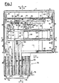
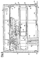
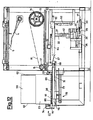
- FIGS. 1, 2, 3 and 4 there is shown a cardboard box forming machine comprising a support frame 1 equipped with a magazine 2 for containing a plurality of blanks 3 arranged one upon the other and folded flat.
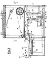
- the machine includes arms 4 (FIGS. 2 and 3) equipped at one end with suction cups 5 and joined at the other end to a shaft 6 induced to rotate in alternating directions by a compressed air piston 8 the rod 9 of which is united with said shaft 6 by a lever 10.
- the shaft 6 bears a sprocket 7 connected by a first chain 11 to a second sprocket 12 which is supported by a shaft 13 on which are keyed two sprockets which in turn drive through chains 16 another pair of sprockets 15 supported by hubs 17 integral with the frame 1 (FIGS. 2 and 3).
- said chains 16 entrain a cursor 18 which slides in lateral guides 19 and is equipped with a plurality of suction cups 20. Said cursor 18, translating forward and backward, ejects the formed boxes as will be described in greater detail below.
- the forming machine is equipped with suction cups 21 and 22 designed to adhere to the opposing smaller side walls 23 and 24 of the blank 3 to which are joined the lower smaller flaps 38 and 39 and upper smaller flaps 56 and 57 (FIGS. 6 and 7).
- the larger side walls 58 and 59 of the blank 3 are equipped with lower larger flaps 60 and 61 and upper larger flaps 62 and 63 (FIGS. 9, 10 and 11).
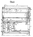
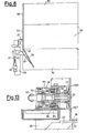
- suction cup 21 (FIG. 4) which goes to adhere to the wall 23 is supported by a first turning arm 25 whose rotation pin 26 positioned next to an edge of the formed box is integral with a lever 27 equipped with a roller 28 which works with a first bar 29 on which are hinged plates 30 which in turn have their fulcrum on a second bar 44 connected to a compressed air piston 31 (FIGS. 1 and 2).
- a recall spring 100 (FIG. 2) stresses the arm 25 in a neutral position.
- the suction cup 22 (FIG. 3) which goes to adhere to the wall 24 of the blank is supported by a second turning arm 32 whose rotation pin 33 is integral with a lever 34 equipped with a roller 35 which works with the bar 29 driven by the compressed air piston 31 (FIG. 1).
- a compressed air piston 36 acts on said lever 34 to take said suction cup 22 into contact with the blank to be opened.
- the turning arms 25 and 32 are equipped with a folding element 37 consisting of a blade designed to engage and fold the lower smaller flaps 38 and 39 of the blank 3.
- Each folding element 37 is integral with an arm 40 which is connected in an articulated manner to the end of the stem 41 of a compressed air piston 42 and can rotate around a pin 43 provided in each of said turning arms 25 and 32.
- Each suction cup 21 and 22 is connected to a compressed air system which creates the necessary vacuum to cause said suction cups to adhere to the surface of the blank.
- the suction cup 21 or (22) is applied to one end of a hollow body 90 which slides horizontally in a housing 91 which is fixed to the turning arm 25 (or 32) and defines abutments 151 for the adjacent carton wall 23 (or 24).
- a front stop 92 and a rear stop 93 are included, whose distance determines the travel of the hollow body 90 within said housing.
- a ring- like cavity 98 which surrounds said hollow body 90 and is in communication with the exterior through an opening 96.
- the internal passage 99 of the hollow body 90 is connected by means of an attachment 97 at the end opposing that to which is applied the suction cup to a means (not shown) designed to create a vacuum in the suction cup.
- Said hollow body also describes in combination with said front stoc 92 a seat 94 for a recall spring 95 which withdraws the suction cup to a neutral position.
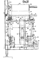
- Said system comprises a carriage 45 equipped with a side support 46 integral with a sleeve 47 which fits over the pin 26 of the first arm 25.
- the carriage 45 consists of a cursor 48 equipped with threaded holes in which are screwed long worm screws 48 integral with sprockets 50 placed at one end thereof and supported by a suitable support 51 (FIGS. 1, 2 and 4).
- the sprockets are connected by a chain 52 to another sprocket 53 (FIG. 2) driven by a crank 54 and supported by a shaft 55 (FIG. 1).
- the chain 52 is sufficiently stretched by means of a chain stretching gear 80.
- a first and a second means which operate immediately after closing of the smaller flaps 38 and 39 respectively and before ejection of the box.
- Said first means consists of a section bar 64 connected by a lever 6 to a compressed air piston 66 and hinged inside supports 82 united to the frame 1 and connected by a roller 81 working with said section bar 64.
- Said second means consists of a plate 67 hinged at 68 to a protruding portion 69 of an ejection bench 70 for the boxes formed and connected to a compressed air piston 71 designed to produce the alternating rotation of said plate 67 around the pin 68.
- a stop member 73 for an ejected formed box which member 73 is preferably in the form of a horizontal bar 74 equipped with at least one pair of suction cups 75, said horizontal bar 74 being adjustable in position to adapt itself to boxes of different sizes.
- said bar 74 is integral with a pair of sliding rods 76 which are connected to a handling unit 78 (FIG. 3) associated with adjusting screws 77 driven by a crank 79 (FIG. 1).
- the forming machine described is d esigned to operate as follows.
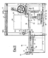
- the forming machine described is shown in the initial position of the forming sequence of a box.
- the arms 4 are rotated in such a manner that the suction cups 5 are in contact with a blank 3 placed on the bottom of the magazine 2.
- the ejection suction cups 20 are in a forward position at the inlet of the ejection bench 70.
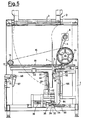
- rotation of the shaft 6 is induced through the lever 10, causing lowering of the arms 4 whose suction cups 5 take a blank 3 from the bottom of the magazine 2 (FIG. 5).
- the sprocket 7 induces rotation of the sprockets 14 and 15, whose connecting chain causes sliding of the cursor 18 supporting the suction cups 20 along the guides 19 away from the bench 70 so that when the arms 4 are in the position rotated downward of FIG. 5 the ejection suction cups 20 have arrived at a backward position beside the suction cups 5 of said arms 4 (FIG. 5).
- the blank 3 will be disposed with the smaller wall 23 against the suction cup 21 and with the adjacent larger side wall 58 against the suction cups 20.
- the compressed air piston 36 acting on the lever 34, induces rotation of the turning arm 35 supporting the suction cup 22, which thus goes to adhere to the smaller wall 24 (FIG. 6).
- FIGS. 6, 7 and 9 for greater drawing clarity the suction cups 5 of the arms 4 and the ejection suction cups 20 along the walls 23 and 58 of the blank have been omitted.
- the larger flap 61 is partially closed first by the lever 67 driven by the piston 71 and then the above closing of the flap 61 is completed simultaneously with the closing of the flap 60 by means of the sectional bar 64 which is rotated by the piston 66.
- the bar 64 rotates until it encounters the stop roller 81 coinciding with a horizontal position under the box almost formed (FIG. 11).
- the compressed air piston 8 is reactivated and rotal:es in the reverse direction the shaft 13, bringing the arms 4 back to the starting position and causing sliding of the cursor 18 toward the bench 70, thus pushing the box, which completes closing of the flap 61, against the suction cups 7S of the stop 73 appropriately positioned on said bench 70; in this step the suction cups 21 and 22 are returned to the retracted position to avoid possible damage to the box, which is hawever held by the suction cups 20 and guided by the abutments 151 of the suction cup housings 91 (Fig. 13).
- the sequence then starts over while the box just formed and ejected is conveyed to a filling station by shifting perpendicularly to the plane of the FIG. 12 sheet using for this purpose means of movement not shown in the drawings.
Landscapes
- Making Paper Articles (AREA)
- Supplying Of Containers To The Packaging Station (AREA)
Claims (12)
Priority Applications (1)
| Application Number | Priority Date | Filing Date | Title |
|---|---|---|---|
| AT87201718T ATE59162T1 (de) | 1986-09-15 | 1987-09-09 | Maschine zum formen von kartons. |
Applications Claiming Priority (2)
| Application Number | Priority Date | Filing Date | Title |
|---|---|---|---|
| IT2301886U | 1986-09-15 | ||
| IT8623018U IT208306Z2 (it) | 1986-09-15 | 1986-09-15 | Formatrice automatica di scatole di cartone. |
Publications (2)
| Publication Number | Publication Date |
|---|---|
| EP0260749A1 EP0260749A1 (de) | 1988-03-23 |
| EP0260749B1 true EP0260749B1 (de) | 1990-12-19 |
Family
ID=11202946
Family Applications (1)
| Application Number | Title | Priority Date | Filing Date |
|---|---|---|---|
| EP87201718A Expired - Lifetime EP0260749B1 (de) | 1986-09-15 | 1987-09-09 | Maschine zum Formen von Kartons |
Country Status (7)
| Country | Link |
|---|---|
| US (1) | US4857038A (de) |
| EP (1) | EP0260749B1 (de) |
| AT (1) | ATE59162T1 (de) |
| CA (1) | CA1273520A (de) |
| DE (1) | DE3766785D1 (de) |
| ES (1) | ES2019092B3 (de) |
| IT (1) | IT208306Z2 (de) |
Families Citing this family (18)
| Publication number | Priority date | Publication date | Assignee | Title |
|---|---|---|---|---|
| IT1236513B (it) * | 1989-10-06 | 1993-03-11 | Augusto Marchetti | Dispositivo per l'alimentazione di cartoni appiattiti e impilati a un magazzino verticale posto sulla sommita' di una macchina formatrice di scatole di cartone. |
| ES2046077B1 (es) * | 1991-07-05 | 1996-11-01 | Boix Maquinaria Sa | Mecanismo regulable para la alimentacoon de planchas de carton en maquinas montadoras de cajas. |
| FR2678580B1 (fr) * | 1991-07-05 | 1994-02-25 | Boix Maquinaria Sa | Perfectionnements sur machines elevatrices de caisses en carton. |
| US5106359A (en) * | 1991-09-16 | 1992-04-21 | Lott Michael E | Carton formation system |
| DE4243139A1 (de) * | 1992-12-19 | 1994-06-23 | Bosch Gmbh Robert | Verfahren und Vorrichtung zum Aufrichten einer Faltschachtel und zum Abkanten deren Verschlußlaschen |
| US5656006A (en) * | 1995-01-13 | 1997-08-12 | Swf Machinery, Inc. | Method and apparatus for forming a work object |
| IT1285518B1 (it) * | 1996-10-01 | 1998-06-08 | Augusto Marchetti | Formatore per scatole parallelepipede di cartone |
| US6070396A (en) * | 1996-11-27 | 2000-06-06 | Specialty Machinery, Inc. | Carton folding apparatus |
| US6669616B1 (en) | 2000-09-26 | 2003-12-30 | Illinois Tool Works Inc. | Compact case forming machine |
| CA2529484C (en) * | 2003-06-17 | 2013-02-19 | Adst Technologies Ltd. | Fluid transfer device having removable needle cartridge |
| US7585265B2 (en) * | 2006-05-15 | 2009-09-08 | Frito-Lay North America, Inc. | Fan-folding mechanism for a case erector |
| CN101730556A (zh) * | 2007-03-06 | 2010-06-09 | Adst技术公司 | 快速注射装置 |
| US7828708B2 (en) * | 2007-10-04 | 2010-11-09 | Wexxar Packaging, Inc. | Case erector and sealer apparatus |
| US10640308B2 (en) | 2014-12-08 | 2020-05-05 | Wexxar Packaging, Inc. | Carton feeding system and method and related carton forming and sealing machine |
| CN106314888A (zh) * | 2016-08-25 | 2017-01-11 | 南通通机股份有限公司 | 一种新型自动开箱机 |
| CN107458659A (zh) * | 2017-07-05 | 2017-12-12 | 成都威斯腾科技实业有限公司 | 一种纸箱智能化自动开箱装置 |
| US11173686B2 (en) | 2017-08-25 | 2021-11-16 | Wexxar Packaging, Inc. | Apparatus and method for accurate carton formation |
| CN111977077A (zh) * | 2020-07-15 | 2020-11-24 | 陶茂龙 | 一种利用激光扫描感应的包装箱自动展开装箱机构 |
Family Cites Families (11)
| Publication number | Priority date | Publication date | Assignee | Title |
|---|---|---|---|---|
| US2289820A (en) * | 1940-03-14 | 1942-07-14 | Standard Knapp Corp | Machine for opening shipping cases from the flat |
| US3040634A (en) * | 1960-04-27 | 1962-06-26 | Fmc Corp | Carton set-up mechanism |
| FR1466367A (fr) * | 1965-10-27 | 1967-01-20 | Seita | Machine à former et présenter les cartons pour alimenter en continu une encartonneuse |
| US3608440A (en) * | 1969-09-17 | 1971-09-28 | Abc Packaging Machine Corp | Machine for opening shipping cases from the flat |
| DE2155230C3 (de) * | 1971-11-06 | 1974-04-18 | Enzinger-Union-Werke Ag, 6800 Mannheim | Kartonauffalter zum Auffalten flacher, vorgefertigter Kartons |
| US3739696A (en) * | 1972-04-21 | 1973-06-19 | R Pearson | Carton delivery and expanding apparatus |
| GB2058706B (en) * | 1979-09-21 | 1983-06-22 | Sm Spa | Carton erecting machines |
| IT1133253B (it) * | 1980-03-18 | 1986-07-09 | Bsp Packaging System | Apparecchiatura per la tramformazione di fustellati in corrispondenti contenitori di forma parallelepipeda |
| US4498893A (en) * | 1982-01-28 | 1985-02-12 | Bemis Company, Inc. | Case erector and bottom sealer apparatus |
| US4632666A (en) * | 1984-03-15 | 1986-12-30 | Durable Packaging | Carton errector apparatus |
| NL8401256A (nl) * | 1984-04-18 | 1985-11-18 | Floraco Bv | Dozenopzet-machine. |
-
1986
- 1986-09-15 IT IT8623018U patent/IT208306Z2/it active
-
1987
- 1987-09-09 ES ES87201718T patent/ES2019092B3/es not_active Expired - Lifetime
- 1987-09-09 EP EP87201718A patent/EP0260749B1/de not_active Expired - Lifetime
- 1987-09-09 AT AT87201718T patent/ATE59162T1/de not_active IP Right Cessation
- 1987-09-09 DE DE8787201718T patent/DE3766785D1/de not_active Expired - Fee Related
- 1987-09-11 CA CA000546719A patent/CA1273520A/en not_active Expired - Fee Related
- 1987-09-15 US US07/096,584 patent/US4857038A/en not_active Expired - Fee Related
Also Published As
| Publication number | Publication date |
|---|---|
| ES2019092B3 (es) | 1991-06-01 |
| IT208306Z2 (it) | 1988-05-28 |
| IT8623018V0 (it) | 1986-09-15 |
| CA1273520A (en) | 1990-09-04 |
| ATE59162T1 (de) | 1991-01-15 |
| US4857038A (en) | 1989-08-15 |
| DE3766785D1 (de) | 1991-01-31 |
| EP0260749A1 (de) | 1988-03-23 |
Similar Documents
| Publication | Publication Date | Title |
|---|---|---|
| EP0260749B1 (de) | Maschine zum Formen von Kartons | |
| EP0766621B1 (de) | Vorrichtung und verfahren zum aufnehmen und aufrichten von kartonzuschnitten | |
| CN1141212C (zh) | 小型箱子成形机 | |
| EP0036399B1 (de) | Vorrichtung zum Transformieren von Zuschnitten in korrespondierende parallelepipedonförmige Behälter | |
| US4170929A (en) | Apparatus for setting up folded cartons | |
| US4807428A (en) | Packing machine for American boxes | |
| EP1357038A1 (de) | Verfahren und Vorrichtung zum Greifen und Öffnen von Schachteln aus ausgestanztem Karton und zum Herstellen von oben offenen Schachteln | |
| USRE30921E (en) | Apparatus for setting up folded cartons | |
| GB1596582A (en) | Wrapping apparatus | |
| US4310323A (en) | Method of manufacture of H-divider containers | |
| EP1584455B1 (de) | Vorrichtung zum Herstellen von Schachteln | |
| CN113479402B (zh) | 一种立式高速开箱机 | |
| US4805380A (en) | Method of and an apparatus for preforming operations in relation to a container sleeve | |
| US3982474A (en) | Case erecting and forming machine | |
| CN212023151U (zh) | 一种高效的新型开箱装置 | |
| US4220076A (en) | Manufacture of H-divider containers | |
| US4315752A (en) | Manufacture of H-dividers | |
| US5664400A (en) | Carton blanks handling mechanism | |
| WO2014066015A1 (en) | Apparatus and methods for folding paper boxes | |
| EP0734952B1 (de) | Vorrichtung zum Entnehmen und Aufrichten von schlauchförmigen Zuschnitten, in Kartoniermaschinen und dergleichen | |
| AU719586B2 (en) | High-speed blank set-up apparatus and methods | |
| CN116476442B (zh) | 一种纸盒冲压成型机 | |
| US4892511A (en) | Method and apparatus for the automatic manufacture of flat bottom bags | |
| US3038388A (en) | Carton folding machines | |
| US5257495A (en) | Automatic packaging machine |
Legal Events
| Date | Code | Title | Description |
|---|---|---|---|
| PUAI | Public reference made under article 153(3) epc to a published international application that has entered the european phase |
Free format text: ORIGINAL CODE: 0009012 |
|
| AK | Designated contracting states |
Kind code of ref document: A1 Designated state(s): AT BE CH DE ES FR GB GR IT LI LU NL SE |
|
| 17P | Request for examination filed |
Effective date: 19880407 |
|
| 17Q | First examination report despatched |
Effective date: 19890421 |
|
| GRAA | (expected) grant |
Free format text: ORIGINAL CODE: 0009210 |
|
| AK | Designated contracting states |
Kind code of ref document: B1 Designated state(s): AT BE CH DE ES FR GB GR IT LI LU NL SE |
|
| PG25 | Lapsed in a contracting state [announced via postgrant information from national office to epo] |
Ref country code: SE Free format text: THE PATENT HAS BEEN ANNULLED BY A DECISION OF A NATIONAL AUTHORITY Effective date: 19901219 Ref country code: GR Free format text: LAPSE BECAUSE OF FAILURE TO SUBMIT A TRANSLATION OF THE DESCRIPTION OR TO PAY THE FEE WITHIN THE PRESCRIBED TIME-LIMIT Effective date: 19901219 Ref country code: BE Effective date: 19901219 Ref country code: AT Effective date: 19901219 |
|
| REF | Corresponds to: |
Ref document number: 59162 Country of ref document: AT Date of ref document: 19910115 Kind code of ref document: T |
|
| ITF | It: translation for a ep patent filed | ||
| REF | Corresponds to: |
Ref document number: 3766785 Country of ref document: DE Date of ref document: 19910131 |
|
| ET | Fr: translation filed | ||
| ITTA | It: last paid annual fee | ||
| PG25 | Lapsed in a contracting state [announced via postgrant information from national office to epo] |
Ref country code: LU Free format text: LAPSE BECAUSE OF NON-PAYMENT OF DUE FEES Effective date: 19910930 |
|
| PLBE | No opposition filed within time limit |
Free format text: ORIGINAL CODE: 0009261 |
|
| STAA | Information on the status of an ep patent application or granted ep patent |
Free format text: STATUS: NO OPPOSITION FILED WITHIN TIME LIMIT |
|
| 26N | No opposition filed | ||
| PGFP | Annual fee paid to national office [announced via postgrant information from national office to epo] |
Ref country code: NL Payment date: 19950929 Year of fee payment: 9 Ref country code: CH Payment date: 19950929 Year of fee payment: 9 |
|
| PG25 | Lapsed in a contracting state [announced via postgrant information from national office to epo] |
Ref country code: LI Effective date: 19960930 Ref country code: CH Effective date: 19960930 |
|
| PG25 | Lapsed in a contracting state [announced via postgrant information from national office to epo] |
Ref country code: NL Effective date: 19970401 |
|
| REG | Reference to a national code |
Ref country code: CH Ref legal event code: PL |
|
| NLV4 | Nl: lapsed or anulled due to non-payment of the annual fee |
Effective date: 19970401 |
|
| PGFP | Annual fee paid to national office [announced via postgrant information from national office to epo] |
Ref country code: FR Payment date: 19970818 Year of fee payment: 11 |
|
| PGFP | Annual fee paid to national office [announced via postgrant information from national office to epo] |
Ref country code: ES Payment date: 19970901 Year of fee payment: 11 |
|
| PG25 | Lapsed in a contracting state [announced via postgrant information from national office to epo] |
Ref country code: ES Free format text: LAPSE BECAUSE OF THE APPLICANT RENOUNCES Effective date: 19980910 |
|
| PG25 | Lapsed in a contracting state [announced via postgrant information from national office to epo] |
Ref country code: FR Free format text: LAPSE BECAUSE OF NON-PAYMENT OF DUE FEES Effective date: 19990531 |
|
| REG | Reference to a national code |
Ref country code: FR Ref legal event code: ST |
|
| REG | Reference to a national code |
Ref country code: ES Ref legal event code: FD2A Effective date: 20001009 |
|
| REG | Reference to a national code |
Ref country code: GB Ref legal event code: IF02 |
|
| PGFP | Annual fee paid to national office [announced via postgrant information from national office to epo] |
Ref country code: GB Payment date: 20030903 Year of fee payment: 17 |
|
| PG25 | Lapsed in a contracting state [announced via postgrant information from national office to epo] |
Ref country code: GB Free format text: LAPSE BECAUSE OF NON-PAYMENT OF DUE FEES Effective date: 20040909 |
|
| PGFP | Annual fee paid to national office [announced via postgrant information from national office to epo] |
Ref country code: DE Payment date: 20040927 Year of fee payment: 18 |
|
| GBPC | Gb: european patent ceased through non-payment of renewal fee |
Effective date: 20040909 |
|
| PG25 | Lapsed in a contracting state [announced via postgrant information from national office to epo] |
Ref country code: IT Free format text: LAPSE BECAUSE OF NON-PAYMENT OF DUE FEES Effective date: 20050909 |
|
| PG25 | Lapsed in a contracting state [announced via postgrant information from national office to epo] |
Ref country code: DE Free format text: LAPSE BECAUSE OF NON-PAYMENT OF DUE FEES Effective date: 20060401 |