EP0259237B1 - Höhenverstellbarer Auflagebock für das Stützen von unter anderem Steinplatten oder Lattenrosten - Google Patents
Höhenverstellbarer Auflagebock für das Stützen von unter anderem Steinplatten oder Lattenrosten Download PDFInfo
- Publication number
- EP0259237B1 EP0259237B1 EP87440050A EP87440050A EP0259237B1 EP 0259237 B1 EP0259237 B1 EP 0259237B1 EP 87440050 A EP87440050 A EP 87440050A EP 87440050 A EP87440050 A EP 87440050A EP 0259237 B1 EP0259237 B1 EP 0259237B1
- Authority
- EP
- European Patent Office
- Prior art keywords
- plate
- height
- base
- stud
- sleeve
- Prior art date
- Legal status (The legal status is an assumption and is not a legal conclusion. Google has not performed a legal analysis and makes no representation as to the accuracy of the status listed.)
- Expired - Lifetime
Links
Images
Classifications
-
- E—FIXED CONSTRUCTIONS
- E04—BUILDING
- E04F—FINISHING WORK ON BUILDINGS, e.g. STAIRS, FLOORS
- E04F15/00—Flooring
- E04F15/02—Flooring or floor layers composed of a number of similar elements
- E04F15/024—Sectional false floors, e.g. computer floors
- E04F15/02447—Supporting structures
- E04F15/02464—Height adjustable elements for supporting the panels or a panel-supporting framework
- E04F15/0247—Screw jacks
- E04F15/02476—Screw jacks height-adjustable from the upper side of the floor
Definitions
- the present invention relates to height-adjustable devices of the type according to the preamble of claim 1 and intended for the support of elements such as slabs or gratings at a certain distance above a laying surface, so as to spare between this surface and these elements a layer of air of variable thickness.
- the present invention also relates to a method of implementing such a device according to claim 2.
- Such devices have been known for a long time in principle, and are generally used on building terraces by being placed for this purpose on the structural slab of a terrace, which is preferably provided with a waterproof coating.
- such studs are generally composed of superimposed and / or nested elements, or comprising adjustment systems by screw, rack or the like.
- the studs formed by interlocking of elements of determined thickness have a height which varies only by discontinuous values, corresponding to the thickness of the element or elements added or removed from the plot. These studs cannot therefore be used when the height between the surface on which the stud rests and the reference support plane for gratings or slabs is set to a value between these discontinuous values and / or which one wishes to compensate for. with precision the variations in parallelism between said surface and said support plane.
- the studs formed by interlocking of elements of determined thickness are increasingly replaced by screw or rack studs, which have a height adjustable continuously between a minimum value and a maximum value.
- the invention makes it possible to overcome these drawbacks of the two types of system by means of a new stud comprising only two elements, namely the fin plate and the base, assembled directly together by a short thread and associated with shims. of calibrated thickness allowing a first rough adjustment of the height, the fine adjustment being obtained by rotation of the base in a smooth bowl practiced in the upper face of the wedge, the plate being immobilized.
- This rotation of the base can be caused by means of a simple screwdriver inserted axially from the top of the stud to a notch provided in the center of the base.
- the pad according to the invention is more particularly defined: by the characterizing part of claim 1. Its method of use is defined: by claim 2.
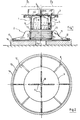
- the pad according to the invention consists of two elements 1 and 2, assembled by screwing.
- the upper element 1 consists of a horizontal plate 3 surmounted by vertical fins 4 intended to be immobilized between the slabs which they support.
- the plate 3 is integral with a sleeve 5 stiffened by external 6 and internal ribs 7.
- the plate 3 is pierced in its center with an oblong hole 8, so as to allow passage for a screwdriver.
- the sleeve 5 has on the outside a series of threads 9.
- Element 2 or base consists of a plate horizontal 12 and a sleeve 10, rigidified together by means of ribs 11.
- the sleeve 10 has internally a thread 13 corresponding to the thread 9.
- the plate 12 has at its center a notch 14 of rectangular shape and into which can be inserted the end of a screwdriver.
- This stud is used in conjunction with a shim 15, chosen from a certain number of calibrated shims, as will be explained in more detail below.
- the device is used in the following manner:
- the total height of the pad 1-2 can vary by approximately 20 mm. If the clearance between the laying surface and the slabs is greater than 20 mm, a shim 15 of the order of 20 mm is placed and it is completed by fine adjustment by rotation of the base 12. It is thus possible, by means of of a stud of simple and robust construction, since involving only a small number of threads 9-13, and of a suitable set of calibrated shims 15, ensuring the maintenance of slabs above a laying surface 16 in a very wide range of thicknesses. Having only one type of stud simplifies and makes the system more economical. Indeed, it is much more economical to provide a series of calibrated shims 15 than a series of screw jacks of different heights, interposed between the two elements 1 and 2 as in the old systems.
Landscapes
- Engineering & Computer Science (AREA)
- Architecture (AREA)
- General Engineering & Computer Science (AREA)
- Civil Engineering (AREA)
- Structural Engineering (AREA)
- Finishing Walls (AREA)
- Road Paving Structures (AREA)
- Polyesters Or Polycarbonates (AREA)
- Led Devices (AREA)
- Semiconductor Lasers (AREA)
- Bidet-Like Cleaning Device And Other Flush Toilet Accessories (AREA)
- A Measuring Device Byusing Mechanical Method (AREA)
- Coupling Device And Connection With Printed Circuit (AREA)
- Forms Removed On Construction Sites Or Auxiliary Members Thereof (AREA)
- Connection Of Plates (AREA)
- Tables And Desks Characterized By Structural Shape (AREA)
- Spinning Or Twisting Of Yarns (AREA)
- Furnace Charging Or Discharging (AREA)
- Conveying And Assembling Of Building Elements In Situ (AREA)
- Floor Finish (AREA)
- Saccharide Compounds (AREA)
Claims (2)
- Höhenverstellbarer Auflagebock zum Abstützen von Platten oder Lattenrosten (D1, D2) über einer Verlegefläche (16), bestehend aus einem oberen Element (1), das von einer Platine (3) gebildet wird, die einstückig zu einer mit einem Außengewinde (9) versehenen Hülse (5) ist, und die mit vertikalen Flügeln (4) ausgestattet ist, die dazu bestimmt sind, zwischen zwei Platten (D1, D2) eingesetzt zu werden, und aus einem unteren Element, dessen Fuß (2) eine horizontale, kreisförmige Platte (12) aufweist, die mit einer mit einem Innengewinde (13) versehenen Hülse (10) ausgestattet ist, das dem Außengewinde (9) des oberen Elements (1) angepaßt ist, wobei die Baueinheitsplatte (12) -hülse (10) verstärkt ist durch Rippen (11), die in gleichmäßigen Abständen am Umfang der Hülse (10) und an der Oberseite der Platte (12) angeordnet sind, wobei dem Auflagebock in der Dicke kalibrierte Unterlagstücke (15) zugeordnet sind, die eine erste Grobeinstellung seiner Höhe ermöglichen, dadurch gekennzeichnet,
daß die Hülse (5) des oberen Elements (1) und die Hülse (10) des Fußes (2) jeweils ein kurzes Gewinde (9,13) aufweisen, die eine Feineinstellung der Höhe des Auflagebocks mittels eines Schraubendrehers, der über eine in der Mitte der Platine (3) angebrachte Bohrung bis zu einer in der Mitte der Platte (12) angebrachten Aussparung (14) eingeführt wird, durch Drehen des Fußes (2) in einer im Unterlagstück (15) angebrachten glatten Schale, ermöglichen. - Verfahren zur Verwendung des höhenverstellbaren Auflagebocks nach Anspruch 1, dadurch gekennzeichnet, daß in einem ersten Schritt eine Grobeinstellung der Höhe mittels in der Dicke kalibrierter Unterlagstücke (15), die man zwischen der Verlegefläche (16) und dem Fuß (2) des Auflagebocks anordnet, durchgeführt wird, und daß man in einem zweiten Schritt eine Feineinstellung dieser Höhe vornimmt, indem man ein Drehen des Fußes (2) in einer im Unterlagstück angebrachten glatten Schale mittels eines Schraubendrehers bewirkt, der axial durch eine in der Mitte der Platine (3) angebrachte Bohrung bis zu einer in der Mitte der Platte (12) angebrachten Aussparung (14) eingeschürt wird.
Priority Applications (1)
| Application Number | Priority Date | Filing Date | Title |
|---|---|---|---|
| AT87440050T ATE65573T1 (de) | 1986-09-04 | 1987-08-14 | Hoehenverstellbarer auflagebock fuer das stuetzen von unter anderem steinplatten oder lattenrosten. |
Applications Claiming Priority (2)
| Application Number | Priority Date | Filing Date | Title |
|---|---|---|---|
| FR8612533A FR2603639B1 (fr) | 1986-09-04 | 1986-09-04 | Plot a hauteur reglable pour le support d'elements tels que dalles ou caillebotis |
| FR8612533 | 1986-09-04 |
Publications (2)
| Publication Number | Publication Date |
|---|---|
| EP0259237A1 EP0259237A1 (de) | 1988-03-09 |
| EP0259237B1 true EP0259237B1 (de) | 1991-07-24 |
Family
ID=9338758
Family Applications (1)
| Application Number | Title | Priority Date | Filing Date |
|---|---|---|---|
| EP87440050A Expired - Lifetime EP0259237B1 (de) | 1986-09-04 | 1987-08-14 | Höhenverstellbarer Auflagebock für das Stützen von unter anderem Steinplatten oder Lattenrosten |
Country Status (9)
| Country | Link |
|---|---|
| EP (1) | EP0259237B1 (de) |
| AT (1) | ATE65573T1 (de) |
| CA (1) | CA1302380C (de) |
| DE (1) | DE3771615D1 (de) |
| DK (1) | DK459887A (de) |
| ES (1) | ES2023937B3 (de) |
| FR (1) | FR2603639B1 (de) |
| GR (1) | GR3002932T3 (de) |
| NO (1) | NO165811C (de) |
Families Citing this family (13)
| Publication number | Priority date | Publication date | Assignee | Title |
|---|---|---|---|---|
| FR2660731B2 (fr) * | 1983-11-23 | 1992-12-11 | Gable Raymond | Dispositif additif au brevet existant permettant une amelioration dans l'utilisation et la pose des dalles au moyen d'une cle speciale. |
| FR2628463B1 (fr) * | 1988-03-10 | 1990-12-07 | Siplast Sa | Plot a hauteur reglable et son application comme support d'elements tels que caillebotis ou dalles |
| GB2227763B (en) * | 1989-02-01 | 1993-09-22 | Tate Access Floors | Self-gridding flooring system |
| FR2658225A1 (fr) * | 1990-02-09 | 1991-08-16 | Soprema Sa | Dallette de matiere plastique destinee au recouvrement des terrasses de batiments. |
| GB2262110B (en) * | 1991-11-11 | 1995-08-09 | Jefferies Robert Clive | A pedestal |
| FR2763506B1 (fr) * | 1997-05-20 | 1999-08-13 | Fabre Pierre Dermo Cosmetique | Composition pour la realisation d'une formulation triphasique emulsionnable, formulation obtenue et association de cyclodextrine et de silice amorphe |
| AT407735B (de) * | 1999-03-17 | 2001-05-25 | Siemens Sgp Verkehrstech Gmbh | Höheneinstellbares auflager für eine bodenplatte eines schienenfahrzeuges |
| FR3026763B1 (fr) | 2014-10-06 | 2017-11-17 | Soprema | Systeme de revetement du type dalles sur plots comprenant au moins un contenant |
| FR3054577B1 (fr) | 2016-08-01 | 2019-08-23 | Soprema | Plot support avec cales integrees |
| FR3096380A1 (fr) | 2019-05-23 | 2020-11-27 | Soprema | Système de revêtement de sol intégrant au moins une bande éclairante ou végétalisée et plateforme circulable le comportant |
| DE102019122783A1 (de) | 2019-08-26 | 2021-03-04 | Kevin Heinrich | Fertigterrasse; Verfahren zur Erstellung einer Fertigterrasse |
| CN113818336B (zh) * | 2021-09-03 | 2023-02-24 | 上海路博减振科技股份有限公司 | 一种调节支座节点位置的方法 |
| CN113897855A (zh) * | 2021-09-08 | 2022-01-07 | 洛阳双瑞特种装备有限公司 | 一种跨座式轨道梁无级调高支座 |
Citations (1)
| Publication number | Priority date | Publication date | Assignee | Title |
|---|---|---|---|---|
| DE1509423A1 (de) * | 1963-05-02 | 1969-01-09 | Hoellfritsch Erich | Aus vorgefertigten Platten zusammengesetzter Estrich |
Family Cites Families (4)
| Publication number | Priority date | Publication date | Assignee | Title |
|---|---|---|---|---|
| DE1509523A1 (de) * | 1962-07-24 | 1969-06-12 | Klenke Bernhard | Schalldaemmende,bewegliche Wandelemente |
| IT7930667U1 (it) * | 1979-04-05 | 1980-10-05 | Galter Snc | Valigetta-borsa portaoggetti con supporto di ancoraggio per applicazioni varie |
| FR2555224B1 (fr) * | 1983-11-21 | 1987-10-02 | Manon Gerard | Plot de support de dalles |
| FR2559528B1 (fr) * | 1984-02-13 | 1986-05-30 | Siplast Sa | Plot a hauteur reglable et son application comme support d'elements tels que caillebotis ou dalles |
-
1986
- 1986-09-04 FR FR8612533A patent/FR2603639B1/fr not_active Expired - Lifetime
-
1987
- 1987-08-14 DE DE8787440050T patent/DE3771615D1/de not_active Expired - Lifetime
- 1987-08-14 AT AT87440050T patent/ATE65573T1/de not_active IP Right Cessation
- 1987-08-14 EP EP87440050A patent/EP0259237B1/de not_active Expired - Lifetime
- 1987-08-14 ES ES87440050T patent/ES2023937B3/es not_active Expired - Lifetime
- 1987-09-02 NO NO873674A patent/NO165811C/no unknown
- 1987-09-03 CA CA000546052A patent/CA1302380C/fr not_active Expired - Lifetime
- 1987-09-03 DK DK459887A patent/DK459887A/da not_active Application Discontinuation
-
1991
- 1991-10-17 GR GR91401565T patent/GR3002932T3/el unknown
Patent Citations (1)
| Publication number | Priority date | Publication date | Assignee | Title |
|---|---|---|---|---|
| DE1509423A1 (de) * | 1963-05-02 | 1969-01-09 | Hoellfritsch Erich | Aus vorgefertigten Platten zusammengesetzter Estrich |
Also Published As
| Publication number | Publication date |
|---|---|
| ES2023937B3 (es) | 1992-02-16 |
| FR2603639A1 (fr) | 1988-03-11 |
| DK459887A (da) | 1988-03-05 |
| EP0259237A1 (de) | 1988-03-09 |
| NO165811C (no) | 1991-04-10 |
| NO873674L (no) | 1988-03-07 |
| GR3002932T3 (en) | 1993-01-25 |
| CA1302380C (fr) | 1992-06-02 |
| DE3771615D1 (de) | 1991-08-29 |
| FR2603639B1 (fr) | 1990-05-18 |
| DK459887D0 (da) | 1987-09-03 |
| NO165811B (no) | 1991-01-02 |
| ATE65573T1 (de) | 1991-08-15 |
| NO873674D0 (no) | 1987-09-02 |
Similar Documents
| Publication | Publication Date | Title |
|---|---|---|
| EP0259237B1 (de) | Höhenverstellbarer Auflagebock für das Stützen von unter anderem Steinplatten oder Lattenrosten | |
| EP1027511B1 (de) | Vorrichtung zum einstellen der neigung der oberfläche einer konstruktion auf stützfüsse | |
| EP0823268B1 (de) | Schuhbindungsvorrichtung für ein Gleitbrett | |
| EP0133839A2 (de) | Plattenlager | |
| EP3279405B1 (de) | Stützklotz mit integrierten passelementen | |
| FR2524515A1 (fr) | Plot support de dalles de revetement de sol | |
| CA2175645A1 (fr) | Pre-molette pour le glantage d'une lentille optique, et son procede de mise en oeuvre | |
| FR2781854A1 (fr) | Piece monobloc pour la realisation d'un mors d'ancrage de cable, et procede de fabrication d'un tel mors | |
| FR2559529A1 (fr) | Plot a hauteur reglable et son application comme support d'elements tels que caillebotis ou dalles | |
| EP0449732B1 (de) | Profil zum Gebrauch bei dem Verlegen von Pflasterung oder von anderen Oberflächenbeschichtungen | |
| FR2559528A1 (fr) | Plot a hauteur reglable et son application comme support d'elements tels que caillebotis ou dalles | |
| FR2785003A1 (fr) | Structure de mur formee par des poutres en un materiau susceptible de se dilater et de retrecir sous l'effet de variations des conditions ambiantes et piscine formee par de telles structures de mur | |
| FR3057594A1 (fr) | Plot d’aide a la pose d’elements de plancher tels que des dalles, systeme de plancher sureleve le comprenant et procede de mise en œuvre de celui-ci | |
| FR2517714A1 (fr) | Procede et dispositif pour la realisation d'une aire de circulation ou plate-forme, sensiblement plane | |
| FR2522045A1 (fr) | Dispositif de support notamment pour dalles de circulation | |
| BE1007688A3 (fr) | Plot a hauteur reglable et son application comme support d'elements tels que caillebotis ou dalles. | |
| FR2540164A1 (fr) | Escalier prefabrique a moyens de montage reglables | |
| EP0485297A1 (de) | Stützfuss für die Bauausführung von zugänglichen Terrassen | |
| FR2525298A1 (fr) | Dispositif d'immobilisation axiale pour tige filetee, ecrou et produits faisant application de ce dispositif | |
| EP1399273B1 (de) | Akustischer wandler unter verwendung eines vorgespannten rings | |
| EP2617916A1 (de) | Befestigungsschuh für einen Geländerpfosten | |
| FR2639666A1 (fr) | Plot reglable pour le support d'elements de sol, tels que dalles, caillebotis, ou analogues | |
| EP3492667A1 (de) | Hilfssystem zur verlegung eines bodenelements wie beispielsweise einer bodenplatte, und verlegeverfahren eines bodenelements mithilfe dieses systems | |
| FR3165909A1 (fr) | Tête pour plot de plancher surélevé | |
| FR3128963A1 (fr) | Profilé de recouvrement d’une tranche d’un élément de construction en suspens, avec butée d’arrêt pour le coulage d’un système d’étanchéité liquide |
Legal Events
| Date | Code | Title | Description |
|---|---|---|---|
| PUAI | Public reference made under article 153(3) epc to a published international application that has entered the european phase |
Free format text: ORIGINAL CODE: 0009012 |
|
| AK | Designated contracting states |
Kind code of ref document: A1 Designated state(s): AT BE CH DE ES GB GR IT LI LU NL SE |
|
| 17P | Request for examination filed |
Effective date: 19880825 |
|
| 17Q | First examination report despatched |
Effective date: 19900111 |
|
| GRAA | (expected) grant |
Free format text: ORIGINAL CODE: 0009210 |
|
| AK | Designated contracting states |
Kind code of ref document: B1 Designated state(s): AT BE CH DE ES GB GR IT LI LU NL SE |
|
| REF | Corresponds to: |
Ref document number: 65573 Country of ref document: AT Date of ref document: 19910815 Kind code of ref document: T |
|
| REF | Corresponds to: |
Ref document number: 3771615 Country of ref document: DE Date of ref document: 19910829 |
|
| ITF | It: translation for a ep patent filed | ||
| GBT | Gb: translation of ep patent filed (gb section 77(6)(a)/1977) | ||
| REG | Reference to a national code |
Ref country code: ES Ref legal event code: FG2A Ref document number: 2023937 Country of ref document: ES Kind code of ref document: B3 |
|
| PLBE | No opposition filed within time limit |
Free format text: ORIGINAL CODE: 0009261 |
|
| STAA | Information on the status of an ep patent application or granted ep patent |
Free format text: STATUS: NO OPPOSITION FILED WITHIN TIME LIMIT |
|
| 26N | No opposition filed | ||
| REG | Reference to a national code |
Ref country code: GR Ref legal event code: FG4A Free format text: 3002932 |
|
| PGFP | Annual fee paid to national office [announced via postgrant information from national office to epo] |
Ref country code: GR Payment date: 19940701 Year of fee payment: 8 |
|
| PGFP | Annual fee paid to national office [announced via postgrant information from national office to epo] |
Ref country code: AT Payment date: 19940711 Year of fee payment: 8 |
|
| PGFP | Annual fee paid to national office [announced via postgrant information from national office to epo] |
Ref country code: ES Payment date: 19940720 Year of fee payment: 8 |
|
| PGFP | Annual fee paid to national office [announced via postgrant information from national office to epo] |
Ref country code: LU Payment date: 19940731 Year of fee payment: 8 |
|
| PGFP | Annual fee paid to national office [announced via postgrant information from national office to epo] |
Ref country code: GB Payment date: 19940804 Year of fee payment: 8 |
|
| PGFP | Annual fee paid to national office [announced via postgrant information from national office to epo] |
Ref country code: SE Payment date: 19940816 Year of fee payment: 8 |
|
| PGFP | Annual fee paid to national office [announced via postgrant information from national office to epo] |
Ref country code: BE Payment date: 19940819 Year of fee payment: 8 |
|
| PGFP | Annual fee paid to national office [announced via postgrant information from national office to epo] |
Ref country code: NL Payment date: 19940831 Year of fee payment: 8 |
|
| EPTA | Lu: last paid annual fee | ||
| EAL | Se: european patent in force in sweden |
Ref document number: 87440050.0 |
|
| PG25 | Lapsed in a contracting state [announced via postgrant information from national office to epo] |
Ref country code: LU Free format text: LAPSE BECAUSE OF NON-PAYMENT OF DUE FEES Effective date: 19950814 Ref country code: GB Effective date: 19950814 Ref country code: AT Effective date: 19950814 |
|
| PG25 | Lapsed in a contracting state [announced via postgrant information from national office to epo] |
Ref country code: SE Effective date: 19950815 |
|
| PG25 | Lapsed in a contracting state [announced via postgrant information from national office to epo] |
Ref country code: ES Free format text: LAPSE BECAUSE OF THE APPLICANT RENOUNCES Effective date: 19950816 |
|
| PG25 | Lapsed in a contracting state [announced via postgrant information from national office to epo] |
Ref country code: BE Effective date: 19950831 |
|
| PG25 | Lapsed in a contracting state [announced via postgrant information from national office to epo] |
Ref country code: GR Free format text: THE PATENT HAS BEEN ANNULLED BY A DECISION OF A NATIONAL AUTHORITY Effective date: 19960228 |
|
| BERE | Be: lapsed |
Owner name: S.A. SOPREMA Effective date: 19950831 |
|
| PG25 | Lapsed in a contracting state [announced via postgrant information from national office to epo] |
Ref country code: NL Effective date: 19960301 |
|
| GBPC | Gb: european patent ceased through non-payment of renewal fee |
Effective date: 19950814 |
|
| REG | Reference to a national code |
Ref country code: GR Ref legal event code: MM2A Free format text: 3002932 |
|
| NLV4 | Nl: lapsed or anulled due to non-payment of the annual fee |
Effective date: 19960301 |
|
| EUG | Se: european patent has lapsed |
Ref document number: 87440050.0 |
|
| PGFP | Annual fee paid to national office [announced via postgrant information from national office to epo] |
Ref country code: CH Payment date: 19980904 Year of fee payment: 12 |
|
| PGFP | Annual fee paid to national office [announced via postgrant information from national office to epo] |
Ref country code: DE Payment date: 19981006 Year of fee payment: 12 |
|
| PG25 | Lapsed in a contracting state [announced via postgrant information from national office to epo] |
Ref country code: LI Free format text: LAPSE BECAUSE OF NON-PAYMENT OF DUE FEES Effective date: 19990831 Ref country code: CH Free format text: LAPSE BECAUSE OF NON-PAYMENT OF DUE FEES Effective date: 19990831 |
|
| REG | Reference to a national code |
Ref country code: ES Ref legal event code: FD2A Effective date: 19991007 |
|
| REG | Reference to a national code |
Ref country code: CH Ref legal event code: PL |
|
| PG25 | Lapsed in a contracting state [announced via postgrant information from national office to epo] |
Ref country code: DE Free format text: LAPSE BECAUSE OF NON-PAYMENT OF DUE FEES Effective date: 20000601 |
|
| PG25 | Lapsed in a contracting state [announced via postgrant information from national office to epo] |
Ref country code: IT Free format text: LAPSE BECAUSE OF NON-PAYMENT OF DUE FEES;WARNING: LAPSES OF ITALIAN PATENTS WITH EFFECTIVE DATE BEFORE 2007 MAY HAVE OCCURRED AT ANY TIME BEFORE 2007. THE CORRECT EFFECTIVE DATE MAY BE DIFFERENT FROM THE ONE RECORDED. Effective date: 20050814 |