EP0259020A2 - Verfahren und Vorrichtung zum Herstellen von Behältern - Google Patents
Verfahren und Vorrichtung zum Herstellen von Behältern Download PDFInfo
- Publication number
- EP0259020A2 EP0259020A2 EP87306985A EP87306985A EP0259020A2 EP 0259020 A2 EP0259020 A2 EP 0259020A2 EP 87306985 A EP87306985 A EP 87306985A EP 87306985 A EP87306985 A EP 87306985A EP 0259020 A2 EP0259020 A2 EP 0259020A2
- Authority
- EP
- European Patent Office
- Prior art keywords
- body portion
- container
- tube
- elongate
- base
- Prior art date
- Legal status (The legal status is an assumption and is not a legal conclusion. Google has not performed a legal analysis and makes no representation as to the accuracy of the status listed.)
- Granted
Links
Images


Classifications
-
- B—PERFORMING OPERATIONS; TRANSPORTING
- B29—WORKING OF PLASTICS; WORKING OF SUBSTANCES IN A PLASTIC STATE IN GENERAL
- B29C—SHAPING OR JOINING OF PLASTICS; SHAPING OF MATERIAL IN A PLASTIC STATE, NOT OTHERWISE PROVIDED FOR; AFTER-TREATMENT OF THE SHAPED PRODUCTS, e.g. REPAIRING
- B29C44/00—Shaping by internal pressure generated in the material, e.g. swelling or foaming ; Producing porous or cellular expanded plastics articles
- B29C44/20—Shaping by internal pressure generated in the material, e.g. swelling or foaming ; Producing porous or cellular expanded plastics articles for articles of indefinite length
- B29C44/32—Incorporating or moulding on preformed parts, e.g. linings, inserts or reinforcements
- B29C44/334—Filling the preformed spaces or cavities
-
- B—PERFORMING OPERATIONS; TRANSPORTING
- B29—WORKING OF PLASTICS; WORKING OF SUBSTANCES IN A PLASTIC STATE IN GENERAL
- B29C—SHAPING OR JOINING OF PLASTICS; SHAPING OF MATERIAL IN A PLASTIC STATE, NOT OTHERWISE PROVIDED FOR; AFTER-TREATMENT OF THE SHAPED PRODUCTS, e.g. REPAIRING
- B29C44/00—Shaping by internal pressure generated in the material, e.g. swelling or foaming ; Producing porous or cellular expanded plastics articles
- B29C44/20—Shaping by internal pressure generated in the material, e.g. swelling or foaming ; Producing porous or cellular expanded plastics articles for articles of indefinite length
- B29C44/32—Incorporating or moulding on preformed parts, e.g. linings, inserts or reinforcements
- B29C44/322—Incorporating or moulding on preformed parts, e.g. linings, inserts or reinforcements the preformed parts being elongated inserts, e.g. cables
- B29C44/324—Incorporating or moulding on preformed parts, e.g. linings, inserts or reinforcements the preformed parts being elongated inserts, e.g. cables the preformed parts being tubular or folded to a tubular shape
-
- B—PERFORMING OPERATIONS; TRANSPORTING
- B29—WORKING OF PLASTICS; WORKING OF SUBSTANCES IN A PLASTIC STATE IN GENERAL
- B29C—SHAPING OR JOINING OF PLASTICS; SHAPING OF MATERIAL IN A PLASTIC STATE, NOT OTHERWISE PROVIDED FOR; AFTER-TREATMENT OF THE SHAPED PRODUCTS, e.g. REPAIRING
- B29C48/00—Extrusion moulding, i.e. expressing the moulding material through a die or nozzle which imparts the desired form; Apparatus therefor
- B29C48/15—Extrusion moulding, i.e. expressing the moulding material through a die or nozzle which imparts the desired form; Apparatus therefor incorporating preformed parts or layers, e.g. extrusion moulding around inserts
- B29C48/151—Coating hollow articles
-
- B—PERFORMING OPERATIONS; TRANSPORTING
- B29—WORKING OF PLASTICS; WORKING OF SUBSTANCES IN A PLASTIC STATE IN GENERAL
- B29D—PRODUCING PARTICULAR ARTICLES FROM PLASTICS OR FROM SUBSTANCES IN A PLASTIC STATE
- B29D22/00—Producing hollow articles
- B29D22/003—Containers for packaging, storing or transporting, e.g. bottles, jars, cans, barrels, tanks
-
- B—PERFORMING OPERATIONS; TRANSPORTING
- B29—WORKING OF PLASTICS; WORKING OF SUBSTANCES IN A PLASTIC STATE IN GENERAL
- B29C—SHAPING OR JOINING OF PLASTICS; SHAPING OF MATERIAL IN A PLASTIC STATE, NOT OTHERWISE PROVIDED FOR; AFTER-TREATMENT OF THE SHAPED PRODUCTS, e.g. REPAIRING
- B29C48/00—Extrusion moulding, i.e. expressing the moulding material through a die or nozzle which imparts the desired form; Apparatus therefor
- B29C48/001—Combinations of extrusion moulding with other shaping operations
- B29C48/0017—Combinations of extrusion moulding with other shaping operations combined with blow-moulding or thermoforming
-
- B—PERFORMING OPERATIONS; TRANSPORTING
- B29—WORKING OF PLASTICS; WORKING OF SUBSTANCES IN A PLASTIC STATE IN GENERAL
- B29C—SHAPING OR JOINING OF PLASTICS; SHAPING OF MATERIAL IN A PLASTIC STATE, NOT OTHERWISE PROVIDED FOR; AFTER-TREATMENT OF THE SHAPED PRODUCTS, e.g. REPAIRING
- B29C48/00—Extrusion moulding, i.e. expressing the moulding material through a die or nozzle which imparts the desired form; Apparatus therefor
- B29C48/001—Combinations of extrusion moulding with other shaping operations
- B29C48/0022—Combinations of extrusion moulding with other shaping operations combined with cutting
-
- B—PERFORMING OPERATIONS; TRANSPORTING
- B29—WORKING OF PLASTICS; WORKING OF SUBSTANCES IN A PLASTIC STATE IN GENERAL
- B29C—SHAPING OR JOINING OF PLASTICS; SHAPING OF MATERIAL IN A PLASTIC STATE, NOT OTHERWISE PROVIDED FOR; AFTER-TREATMENT OF THE SHAPED PRODUCTS, e.g. REPAIRING
- B29C48/00—Extrusion moulding, i.e. expressing the moulding material through a die or nozzle which imparts the desired form; Apparatus therefor
- B29C48/03—Extrusion moulding, i.e. expressing the moulding material through a die or nozzle which imparts the desired form; Apparatus therefor characterised by the shape of the extruded material at extrusion
- B29C48/07—Flat, e.g. panels
- B29C48/08—Flat, e.g. panels flexible, e.g. films
-
- B—PERFORMING OPERATIONS; TRANSPORTING
- B29—WORKING OF PLASTICS; WORKING OF SUBSTANCES IN A PLASTIC STATE IN GENERAL
- B29C—SHAPING OR JOINING OF PLASTICS; SHAPING OF MATERIAL IN A PLASTIC STATE, NOT OTHERWISE PROVIDED FOR; AFTER-TREATMENT OF THE SHAPED PRODUCTS, e.g. REPAIRING
- B29C48/00—Extrusion moulding, i.e. expressing the moulding material through a die or nozzle which imparts the desired form; Apparatus therefor
- B29C48/03—Extrusion moulding, i.e. expressing the moulding material through a die or nozzle which imparts the desired form; Apparatus therefor characterised by the shape of the extruded material at extrusion
- B29C48/12—Articles with an irregular circumference when viewed in cross-section, e.g. window profiles
-
- B—PERFORMING OPERATIONS; TRANSPORTING
- B29—WORKING OF PLASTICS; WORKING OF SUBSTANCES IN A PLASTIC STATE IN GENERAL
- B29L—INDEXING SCHEME ASSOCIATED WITH SUBCLASS B29C, RELATING TO PARTICULAR ARTICLES
- B29L2031/00—Other particular articles
- B29L2031/712—Containers; Packaging elements or accessories, Packages
Definitions
- the present invention relates to a method of and apparatus for manufacturing containers.
- the present invention aims to overcome the above discussed problems of the prior art.
- the present invention provides a method of manufacturing containers, the method comprising the steps of:-
- the present invention further provides apparatus for manufacturing containers, comprising an extrusion device for extruding an elongate tube of plastics material, the tube having a rectangular cross-section and an elongate central cylindrical cavity, a cutting device for cutting the tube transversely into a plurality of container body portions, a first sealing means for sealing a base to one end of each body portion and a second sealing means for sealing a top to the other end of each body portion.
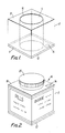
- a container body portion 2 has an elongate central cylindrical cavity 4 extending between two end faces 6, 8 thereof.
- the cross-section of the body portion 2 is rectangular, preferably square, so that the external longitudinal surface of the body portion 2 is comprised of four flat faces.
- the body portion 2 is composed of a foamed plastics material, such as polystyrene, which has been formed by extrusion.
- the cylindrical cavity 4 is lined with a tubular sleeve l0 of sterile plastics material which has been co-extruded with the body portion 2.
- a base l2 is sealed to one end face 6 of the body portion 2.
- the base l2 comprises a plastics layer which has been heat sealed or adhered to the end face 6.
- the base l2 is a pressure sensitive vinyl which has been thermoformed onto the end face 6.
- the base l2 is a vinyl sheet which is adhered to the end face 6 by a layer of adhesive.
- the base l2 may be provided with a strip of magnetic material l4 for recording information relating to the container.
- the strip of magnetic material l4 could store information such as the filling date of the container, the serial number of the product, the maximum and minimum temperature to which the contents of the container can be subjected without degradation, etc.
- FIG 2 shows a container l6 made in accordance with the invention which incorporates the body portion 2 and base l2 assembly shown in Figure l.
- the container l6 has a top l8 which is typically of plastics material and is sealed to the other end face 8 of the body portion either by heat sealing or by an adhesive.
- the top l8 includes a removable closure 20 for access to the cavity 4. If desired, the top l8 may be provided with a tamper indicative band for indicating whether or not the container has been opened. Furthermore, the top l8 may be provided with the strip of magnetic material l4 rather than the base l2.
- a label 20, which is typically a self-adhesive paper label, is applied to the outer surface of the body portion 2.
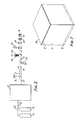
- An extrusion apparatus 22 is fed with a supply of foamable plastics material to form the body portion 2 and with a supply of plastics material to form the tubular sleeve l0 from respective reservoirs 24, 25 via respective conduits 28, 30.
- the extrusion apparatus 22 is of a known construction and has a die which forms an elongate foamed tube 32 which has a rectangular cross-section and a central cylindrical cavity which is lined with sleeve l0.
- the extruded tube 32 exits from the extrusion apparatus 22 and is passed to a cutting station at which a cutter 34 cuts the tube transversely into a plurality of body portions 2.
- the body portions 2 are then conveyed by a conveyor (not shown) to a rotating station 36 at which the body portions are turned through 90° by a rotating device (not shown) so that a transverse end face of each of the body portions 2 is directed downwardly.
- the body portions 2 then are passed by the conveyor to a base applying station 38 at which a base l2 is sealed to each body portion 2.
- the body portion 2 and base l2 assembly is then conveyed to a filling station 40 at which the cavity in the body portion 2 is filled with a specified amount of a product, e.g. pills 42, from a hopper 44.
- the filled body portion 2 then passes to a top applying station 46 where a top l8 is sealed to the upwardly directed end face 8 of the body portion to form the container l6.
- the filled containers l6 are then conveyed to a label applying station 48 at which labels 20 are applied to the containers l6.
- pack information is recorded onto the strip of magnetic material l4 at this stage.
- the containers l6 are then packaged or stacked in bulk on a pallet (not shown).
- An extrusion apparatus comprises an extrusion die 52 mounted on a base 54.
- the die 52 has a square internal cavity 56 with radiased corners 58.
- Mounted in the centre of the cavity 56 is a cylindrical mandrel 60 which extends longitudinally therealong.
- the mandrel 60 is fixed to the die 52 at an input end 62 of the die 52 by means of a support member 64 which extends between the top of the end of the mandrel 60 and an upper part of the die 52.
- a transverse annular wall 66 which separates the input end 62 of the die 52 from the output end 68, which incorporates a foam-forming chamber 70.
- the radius of the circular hole in the annular wall 66 is slightly greater than that of the mandrel 60 whereby a small gap surrounds the mandrel 60.
- An axle 72 for supporting a roll of plastics sheet 74 is located adjacent the input end 62 of the die 52.
- a supply of foam-forming material 76 is connected to the foam-forming chamber 70.
- a welding device 78 such as an ultrasonic welding unit or a heat welding device is provided upstream of the annular wall 66 and above the mandrel 60.
- a roll of plastics sheet 74, such as polyethylene, vinyl, or polyester sheet is mounted on the axle 72 and fed off therefrom.
- the sheet 80 has a width which is substantially the same as or slightly greater than the circumference of the mandrel 60.
- the sheet 80 is wrapped around the mandrel 60 from the bottom of the mandrel 60 to the top thereby to form an elongate join above the top of the mandrel 60.
- the welding device 78 welds the join together at a welded region 8l thereby to form a tube 82 of plastics sheet which closely surrounds the mandrel 60.
- the tube 82 passes through the annular wall 66 into the foam-forming chamber 70 into which foam forming material is injected.
- the foam-forming material expands in the foam-forming chamber 70 to fill the foam-forming cavity and form an elongate tube 84 of foam around the tube 82 of plastics material.
- the composite tubular structure is continuously printed out of the die 52 by the pressure of the injected foam-forming material.
- the plastics sheet may be a tube of heat-shrinkable material which is heat shrunk around the elongate foam tube or a sheet which is wrapped around the elongate foam tube and then joined together along a seam e.g. by heat welding or by means of an adhesive.
- the extruded foam tube may be cut into lengths of e.g. 5 metres and then those lengths can subsequently be cut into a plurality of individual container body portions 2.
- Figure 7 shows an alternative embodiment of a container made in accordance with the present invention.
- the container body portion 2 and the base l2 are the same as those of Figures l and 2.
- the top 86 consists of a laminar material, such as a vinyl sheet, which is adhered or welded to the end face 8 of the container body portion 2.
- the laminar top 86 seals the container but can be removed to open the container by being torn off.
- This structure can provide a "child-proof" container suitable for pharmaceutical pills or capsules.
- the laminar top 86 could be attached to the body portion 2 so as to be separable therefrom by tearing.
- the laminar top 86 may be provided at one cover thereof with an unattached tab portion which can easily be gripped manually and pulled so as to open the container.
- Figure 8 shows a container in accordance with a further embodiment of the present invention.
- the container body portion 2 is the same as that of the previous figures but the top and base are not.
- the base 88 is of a pre-moulded plastics and consists of a base wall 90 which has integral therewith a centrally located tubular cylindrical flange 92.
- the flange 92 is adapted closely to fit inside the lined cylindrical cavity 4.
- the flange 92 typically has a height of 5 to l0 millimetres and therefore has a relatively large outer tubular area which is adjacent the tubular sleeve l0.
- the base 88 may be held in position merely by a press-fit, but it is preferred, especially when the container is intended to hold liquids and so is required to be impervious to liquids, to adhere together the tubular sleeve l0 and the base 88. This may be done either by means of adhesive or by welding e.g. by heat, the tubular sleeve l0 and the flange 92 together. If desired, the flange 92 may have a much greater height than that illustrated in Figure 8 thereby to extend a substantial length into the cylindrical cavity 4. In this way, the flange 92 can enhance the strength of the container. Furthermore, the base may be formed of or coated with a non-slip material e.g.
- the top 94 comprises a bung 96 of polystyrene or vinyl and a sheet 98 of vinyl which is adhered or welded over the top of the body portion 2.
- the bung 96 is initially pressed into the cylindrical cavity 4 and then the vinyl sheet 98 is laid thereover. The vinyl sheet 98 is then adhered or welded to the bung 96 thereby to form an integral top 94.
- This arrangement is convenient to produce in a continuous manufacturing process without the requirement for pre-moulded tops.
- Figure 9 shows yet another embodiment of a container in accordance with the invention.
- the base l00 is pre-moulded and comprises a base wall l02 with an integral disc-like bung l04.
- the bung l04 is welded to the tubular sleeve l0 in the manner described with reference to Figure 8.
- the top l06 consists of a vinyl sheet l08 with a circular indent ll0 which is press-fit into the cylindrical cavity 4.
- the top l06 is fixed to the body portion 2 by welding.
- Figure l0 shows an alternative embodiment of a container in accordane with the invention in which the top ll2 of the container is formed of a vinyl sheet which is adhered or welded to the body portion 2.
- the vinyl sheet ll2 is provided with a circular line of perforations ll4 which can be broken thereby to access the inside of the container. It will be apparent that the line of perforations may be of alternative arrangements from that illustrated.
- Figure ll shows a container body portion in accordance with a further embodiment of the present invention.
- the container body portion ll6 consists not only of the centrally-located cylindrical cavity 4 but also of a second elongate, preferably cylindrical cavity ll8 in a corner thereof.
- the second cavity ll8 may be employed to contain a product or substance relating to that which is intended to be contained within the first cylindrical cavity 4.
- the second cavity ll8 may contain a pigment or a solvent for the paint.
- the second cavity ll8 may be dimensioned so as to be able to hold a paint brush or other article.
- Figure l2 shows yet another container in accordance with the invention.
- the illustrated container l20 consists of a body portion and a base which is similar to those described hereinabove.
- the top consists of a block l22 e.g. of foamed material which is held on the body portion l24 by means of two rods l26, l28 which extend between the block l22 and the body l24.
- the rods l26, l28 are slidably mounted in respective bores in respective corners of the block l22 and the body portion l24.
- the external shape of the containers made in accordance with the invention is not related to the shape of the cavity therein.
- the outer shape and dimensions can be selected as desired without any effect on the shape and dimensions of the cavity whereby the containers can be made so as to reflect the dimensions of a pallet so as to facilitate stacking of a number of containers on the pallet in an efficient manner.
- a pill container could have a body portion 2 with external dimensions of 50 mm ⁇ 50 mm ⁇ 50 mm with an internal cylindrical cavity having a diameter of either l0 mm for a given number of small pills or 20 mm for ten times that given number of small pills.
- containers of the same external dimensions can be used to package varying amounts of products, with the diameter of the cavity being selected in accordance with the required capicity of the container.
- the provision of uniform external shape and dimension of the containers facilitate the manufacture of different capacity containers since it is only required to adjust the diameter of the cavity. This could be done by changing the mandrel in the extrusion apparatus which is used to form the cavity.
- the method of the present invention can permit on-site manufacture of containers as part of the filling line. This obviates the need for stockholding of containers since the containers are manufactured just prior to being filled in a continuous process.
- the external shape of the containers made in accordance with the invention has an advantage over the known cylindrical containers in that it is much easier to label containers having flat faces than containers having curved faces. This particularly applies when the labels are applied by an automatic labelling machine. Also, the end user of the container is likely to find it more easy to hold a container having a rectangular or square cross section than a container having a circular cross-section.
Landscapes
- Engineering & Computer Science (AREA)
- Mechanical Engineering (AREA)
- Supplying Of Containers To The Packaging Station (AREA)
- Extrusion Moulding Of Plastics Or The Like (AREA)
- Making Paper Articles (AREA)
- Shaping Of Tube Ends By Bending Or Straightening (AREA)
- Packages (AREA)
Applications Claiming Priority (4)
| Application Number | Priority Date | Filing Date | Title |
|---|---|---|---|
| GB8619337 | 1986-08-07 | ||
| GB868619337A GB8619337D0 (en) | 1986-08-07 | 1986-08-07 | Containers |
| GB8630546 | 1986-12-22 | ||
| GB8630546A GB2193943B (en) | 1986-08-07 | 1986-12-22 | Manufacturing containers |
Publications (3)
| Publication Number | Publication Date |
|---|---|
| EP0259020A2 true EP0259020A2 (de) | 1988-03-09 |
| EP0259020A3 EP0259020A3 (en) | 1989-10-25 |
| EP0259020B1 EP0259020B1 (de) | 1995-02-22 |
Family
ID=26291148
Family Applications (1)
| Application Number | Title | Priority Date | Filing Date |
|---|---|---|---|
| EP87306985A Expired - Lifetime EP0259020B1 (de) | 1986-08-07 | 1987-08-06 | Verfahren und Vorrichtung zum Herstellen von Behältern |
Country Status (5)
| Country | Link |
|---|---|
| EP (1) | EP0259020B1 (de) |
| AT (1) | ATE118731T1 (de) |
| CA (1) | CA1270358C (de) |
| DE (1) | DE3751080T2 (de) |
| HK (1) | HK138895A (de) |
Cited By (3)
| Publication number | Priority date | Publication date | Assignee | Title |
|---|---|---|---|---|
| EP0707988A3 (de) * | 1994-10-21 | 1998-01-21 | Gencorp Inc. | Lagerbuchse für Drehstabstabilisator und ihr Herstellungsverfahren |
| EP0868995A2 (de) * | 1997-04-01 | 1998-10-07 | Grand Polymer Co., Ltd. | Verfahren zur Herstellung einer Aussenprofielleiste für Fahrzeuge, laminierteSchicht oder Folie zur Verwendung in diesem Verfahren und eine Aussenprofielliste für Fahrzeuge |
| US6457223B1 (en) | 1999-06-07 | 2002-10-01 | Crown Cork & Seal Technologies Corporation | Method of manufacturing cosmetic container |
Citations (10)
| Publication number | Priority date | Publication date | Assignee | Title |
|---|---|---|---|---|
| US2913768A (en) * | 1953-11-25 | 1959-11-24 | American Can Co | Method for printing and forming non-circular tubular plastic bodies |
| DE2435370A1 (de) * | 1974-07-23 | 1976-02-05 | Rakennusmuovi Oy | Duesenkopf zum herstellen von isolierrohr |
| US4024694A (en) * | 1976-06-18 | 1977-05-24 | Marvin Cooper | Apparatus for filling and assembling cups and process therefore |
| DE3113810A1 (de) * | 1981-04-06 | 1982-10-21 | Gebrüder Kömmerling Kunststoffwerke GmbH, 6780 Pirmasens | Kunststoff-profilstab |
| EP0126575A2 (de) * | 1983-05-09 | 1984-11-28 | Cosden Technology Inc. | Durch Reibung geschweisste beschichtete Behälter |
| US4531991A (en) * | 1981-05-25 | 1985-07-30 | Kabel- Und Metallwerke Gutehoffnungshuette A.G. | Heat-insulating tubing |
| EP0156750A1 (de) * | 1984-02-24 | 1985-10-02 | Contapal Patent Ag | Verstärkter Formkörper aus Polystyrol und Verfahren zu seiner Herstellung |
| GB2156265A (en) * | 1984-03-26 | 1985-10-09 | Vercon Inc | Manufacturing thermoplastic tubular containers |
| JPS60242514A (ja) * | 1984-05-16 | 1985-12-02 | Toshiba Corp | 磁気記録媒体 |
| US4569875A (en) * | 1983-02-03 | 1986-02-11 | Rohm Gmbh Chemische Fabrik | Multilayer web panel and a process for its manufacture |
-
1987
- 1987-08-04 CA CA543707A patent/CA1270358C/en not_active Expired
- 1987-08-06 AT AT87306985T patent/ATE118731T1/de not_active IP Right Cessation
- 1987-08-06 EP EP87306985A patent/EP0259020B1/de not_active Expired - Lifetime
- 1987-08-06 DE DE3751080T patent/DE3751080T2/de not_active Expired - Fee Related
-
1995
- 1995-08-31 HK HK138895A patent/HK138895A/xx not_active IP Right Cessation
Patent Citations (10)
| Publication number | Priority date | Publication date | Assignee | Title |
|---|---|---|---|---|
| US2913768A (en) * | 1953-11-25 | 1959-11-24 | American Can Co | Method for printing and forming non-circular tubular plastic bodies |
| DE2435370A1 (de) * | 1974-07-23 | 1976-02-05 | Rakennusmuovi Oy | Duesenkopf zum herstellen von isolierrohr |
| US4024694A (en) * | 1976-06-18 | 1977-05-24 | Marvin Cooper | Apparatus for filling and assembling cups and process therefore |
| DE3113810A1 (de) * | 1981-04-06 | 1982-10-21 | Gebrüder Kömmerling Kunststoffwerke GmbH, 6780 Pirmasens | Kunststoff-profilstab |
| US4531991A (en) * | 1981-05-25 | 1985-07-30 | Kabel- Und Metallwerke Gutehoffnungshuette A.G. | Heat-insulating tubing |
| US4569875A (en) * | 1983-02-03 | 1986-02-11 | Rohm Gmbh Chemische Fabrik | Multilayer web panel and a process for its manufacture |
| EP0126575A2 (de) * | 1983-05-09 | 1984-11-28 | Cosden Technology Inc. | Durch Reibung geschweisste beschichtete Behälter |
| EP0156750A1 (de) * | 1984-02-24 | 1985-10-02 | Contapal Patent Ag | Verstärkter Formkörper aus Polystyrol und Verfahren zu seiner Herstellung |
| GB2156265A (en) * | 1984-03-26 | 1985-10-09 | Vercon Inc | Manufacturing thermoplastic tubular containers |
| JPS60242514A (ja) * | 1984-05-16 | 1985-12-02 | Toshiba Corp | 磁気記録媒体 |
Non-Patent Citations (1)
| Title |
|---|
| JAPANESE PATENT GAZETTE, week 8603, Derwent Publications, section CH, class L, no. 86-018266 (03), London, GB; & JP-A-60 242514 (TOSHIBA K.K.) 02-12-1985 * |
Cited By (5)
| Publication number | Priority date | Publication date | Assignee | Title |
|---|---|---|---|---|
| EP0707988A3 (de) * | 1994-10-21 | 1998-01-21 | Gencorp Inc. | Lagerbuchse für Drehstabstabilisator und ihr Herstellungsverfahren |
| EP0868995A2 (de) * | 1997-04-01 | 1998-10-07 | Grand Polymer Co., Ltd. | Verfahren zur Herstellung einer Aussenprofielleiste für Fahrzeuge, laminierteSchicht oder Folie zur Verwendung in diesem Verfahren und eine Aussenprofielliste für Fahrzeuge |
| EP0868995A3 (de) * | 1997-04-01 | 1999-04-28 | Grand Polymer Co., Ltd. | Verfahren zur Herstellung einer Aussenprofilleiste für Fahrzeuge, laminierte Schicht oder Folie zur Verwendung in diesem Verfahren und eine Aussenprofilleiste für Fahrzeuge |
| US6110547A (en) * | 1997-04-01 | 2000-08-29 | Grand Polymer Co., Ltd. | Method of molding automobile outer trim part, laminated film or sheet for use therein and automobile outer trim part |
| US6457223B1 (en) | 1999-06-07 | 2002-10-01 | Crown Cork & Seal Technologies Corporation | Method of manufacturing cosmetic container |
Also Published As
| Publication number | Publication date |
|---|---|
| CA1270358A (en) | 1990-06-19 |
| CA1270358C (en) | 1990-06-19 |
| DE3751080D1 (de) | 1995-03-30 |
| EP0259020B1 (de) | 1995-02-22 |
| HK138895A (en) | 1995-09-08 |
| ATE118731T1 (de) | 1995-03-15 |
| EP0259020A3 (en) | 1989-10-25 |
| DE3751080T2 (de) | 1995-08-03 |
Similar Documents
| Publication | Publication Date | Title |
|---|---|---|
| CA2332562C (en) | A disposable liquid containing and dispensing package and method for its manufacture | |
| US4384440A (en) | Method for the continuous manufacture of packing containers | |
| EP0278130B1 (de) | Verpackung mit glatter äusserer Oberfläche, Verfahren zu ihrer Herstellung und dazu verwendete Folienbandrolle | |
| EP0419068B1 (de) | Verpackung aus Karton und Kunststoff | |
| US5337539A (en) | Method of producing flexible suspendible pouches and pouch produced therefrom | |
| US3354601A (en) | Method of making stand-up package | |
| US4834823A (en) | Package for flowable filling materials having a re-closable opening | |
| US5333439A (en) | Hot-melt pressure sensitive adhesive packaging, preform, and method | |
| US4216639A (en) | Process of making containers made of thin pliable synthetic material | |
| US3659777A (en) | Reinforced package | |
| US4781773A (en) | Manufacturing containers from multilayered material | |
| US5169470A (en) | Method of extrusion blow molding into paperboard inserts to form a composite package | |
| RO117364B1 (ro) | Procedeu si instalatie pentru producerea pungilor de ambalare | |
| EP0259020B1 (de) | Verfahren und Vorrichtung zum Herstellen von Behältern | |
| EP3253668B1 (de) | Kunststoffbecher mit einer dünnen aussenhülle und nahrungsmittelpackung mit solchen bechern | |
| GB2193943A (en) | Manufacturing containers | |
| EP1135307B1 (de) | Behälter aus flexiblem material mit standfestem boden sowie verfahren zur dessen herstellung | |
| JP2632637B2 (ja) | 積層されたチューブ状胴部を連続的に形成するための方法及び装置 | |
| JP2654978B2 (ja) | 積層状態の管状胴部及びその形成方法 | |
| JP2002255277A (ja) | 軟包材フイルムシートを用いた食品包装体及び食品の取り出し方法 | |
| CA2270686A1 (en) | Triangular composite container | |
| CN211197141U (zh) | 一种塑料外包装袋 | |
| US20020073656A1 (en) | Method and apparatus for forming, filling and sealing tubular packaging | |
| JPH0627547Y2 (ja) | 多層フィルム保形容器 | |
| JPH02301420A (ja) | 有底ネット容器の製造方法および装置 |
Legal Events
| Date | Code | Title | Description |
|---|---|---|---|
| PUAI | Public reference made under article 153(3) epc to a published international application that has entered the european phase |
Free format text: ORIGINAL CODE: 0009012 |
|
| AK | Designated contracting states |
Kind code of ref document: A2 Designated state(s): AT BE CH DE ES FR GB GR IT LI LU NL SE |
|
| PUAL | Search report despatched |
Free format text: ORIGINAL CODE: 0009013 |
|
| AK | Designated contracting states |
Kind code of ref document: A3 Designated state(s): AT BE CH DE ES FR GB GR IT LI LU NL SE |
|
| 17P | Request for examination filed |
Effective date: 19900411 |
|
| 17Q | First examination report despatched |
Effective date: 19910618 |
|
| GRAA | (expected) grant |
Free format text: ORIGINAL CODE: 0009210 |
|
| AK | Designated contracting states |
Kind code of ref document: B1 Designated state(s): AT BE CH DE ES FR GB GR IT LI LU NL SE |
|
| PG25 | Lapsed in a contracting state [announced via postgrant information from national office to epo] |
Ref country code: NL Free format text: LAPSE BECAUSE OF FAILURE TO SUBMIT A TRANSLATION OF THE DESCRIPTION OR TO PAY THE FEE WITHIN THE PRESCRIBED TIME-LIMIT Effective date: 19950222 Ref country code: LI Effective date: 19950222 Ref country code: GR Free format text: LAPSE BECAUSE OF FAILURE TO SUBMIT A TRANSLATION OF THE DESCRIPTION OR TO PAY THE FEE WITHIN THE PRESCRIBED TIME-LIMIT Effective date: 19950222 Ref country code: CH Effective date: 19950222 Ref country code: BE Effective date: 19950222 Ref country code: AT Effective date: 19950222 |
|
| REF | Corresponds to: |
Ref document number: 118731 Country of ref document: AT Date of ref document: 19950315 Kind code of ref document: T |
|
| REF | Corresponds to: |
Ref document number: 3751080 Country of ref document: DE Date of ref document: 19950330 |
|
| ITF | It: translation for a ep patent filed |
Owner name: SOCIETA' ITALIANA BREVETTI S.P.A. |
|
| ET | Fr: translation filed | ||
| PG25 | Lapsed in a contracting state [announced via postgrant information from national office to epo] |
Ref country code: ES Free format text: LAPSE BECAUSE OF FAILURE TO SUBMIT A TRANSLATION OF THE DESCRIPTION OR TO PAY THE FEE WITHIN THE PRESCRIBED TIME-LIMIT Effective date: 19950602 |
|
| REG | Reference to a national code |
Ref country code: CH Ref legal event code: PL |
|
| PG25 | Lapsed in a contracting state [announced via postgrant information from national office to epo] |
Ref country code: LU Free format text: LAPSE BECAUSE OF NON-PAYMENT OF DUE FEES Effective date: 19950831 |
|
| NLV1 | Nl: lapsed or annulled due to failure to fulfill the requirements of art. 29p and 29m of the patents act | ||
| PLBE | No opposition filed within time limit |
Free format text: ORIGINAL CODE: 0009261 |
|
| STAA | Information on the status of an ep patent application or granted ep patent |
Free format text: STATUS: NO OPPOSITION FILED WITHIN TIME LIMIT |
|
| 26N | No opposition filed | ||
| PGFP | Annual fee paid to national office [announced via postgrant information from national office to epo] |
Ref country code: SE Payment date: 20000717 Year of fee payment: 14 |
|
| PGFP | Annual fee paid to national office [announced via postgrant information from national office to epo] |
Ref country code: FR Payment date: 20000724 Year of fee payment: 14 |
|
| PGFP | Annual fee paid to national office [announced via postgrant information from national office to epo] |
Ref country code: GB Payment date: 20000727 Year of fee payment: 14 |
|
| PGFP | Annual fee paid to national office [announced via postgrant information from national office to epo] |
Ref country code: DE Payment date: 20000927 Year of fee payment: 14 |
|
| PG25 | Lapsed in a contracting state [announced via postgrant information from national office to epo] |
Ref country code: GB Free format text: LAPSE BECAUSE OF NON-PAYMENT OF DUE FEES Effective date: 20010806 |
|
| PG25 | Lapsed in a contracting state [announced via postgrant information from national office to epo] |
Ref country code: SE Free format text: LAPSE BECAUSE OF NON-PAYMENT OF DUE FEES Effective date: 20010807 |
|
| GBPC | Gb: european patent ceased through non-payment of renewal fee |
Effective date: 20010806 |
|
| EUG | Se: european patent has lapsed |
Ref document number: 87306985.0 |
|
| PG25 | Lapsed in a contracting state [announced via postgrant information from national office to epo] |
Ref country code: FR Free format text: LAPSE BECAUSE OF NON-PAYMENT OF DUE FEES Effective date: 20020430 |
|
| PG25 | Lapsed in a contracting state [announced via postgrant information from national office to epo] |
Ref country code: DE Free format text: LAPSE BECAUSE OF NON-PAYMENT OF DUE FEES Effective date: 20020501 |
|
| REG | Reference to a national code |
Ref country code: FR Ref legal event code: ST |
|
| PG25 | Lapsed in a contracting state [announced via postgrant information from national office to epo] |
Ref country code: IT Free format text: LAPSE BECAUSE OF NON-PAYMENT OF DUE FEES Effective date: 20050806 |