EP0258970A2 - Verfahren und Vorrichtung zum Orientieren von Behälterenden - Google Patents
Verfahren und Vorrichtung zum Orientieren von Behälterenden Download PDFInfo
- Publication number
- EP0258970A2 EP0258970A2 EP87305729A EP87305729A EP0258970A2 EP 0258970 A2 EP0258970 A2 EP 0258970A2 EP 87305729 A EP87305729 A EP 87305729A EP 87305729 A EP87305729 A EP 87305729A EP 0258970 A2 EP0258970 A2 EP 0258970A2
- Authority
- EP
- European Patent Office
- Prior art keywords
- orientating
- aperture
- station
- rotation
- centre
- Prior art date
- Legal status (The legal status is an assumption and is not a legal conclusion. Google has not performed a legal analysis and makes no representation as to the accuracy of the status listed.)
- Withdrawn
Links
- 238000000034 method Methods 0.000 title claims description 11
- 238000000465 moulding Methods 0.000 claims abstract description 6
- 238000001746 injection moulding Methods 0.000 claims description 2
- 239000000463 material Substances 0.000 claims description 2
- 230000000452 restraining effect Effects 0.000 claims 2
- 229920003023 plastic Polymers 0.000 abstract description 2
- 239000004033 plastic Substances 0.000 abstract description 2
- 238000006073 displacement reaction Methods 0.000 description 3
- 239000000969 carrier Substances 0.000 description 2
- 241000282472 Canis lupus familiaris Species 0.000 description 1
- 230000015572 biosynthetic process Effects 0.000 description 1
- 230000000694 effects Effects 0.000 description 1
- 230000002028 premature Effects 0.000 description 1
Images

Classifications
-
- B—PERFORMING OPERATIONS; TRANSPORTING
- B21—MECHANICAL METAL-WORKING WITHOUT ESSENTIALLY REMOVING MATERIAL; PUNCHING METAL
- B21D—WORKING OR PROCESSING OF SHEET METAL OR METAL TUBES, RODS OR PROFILES WITHOUT ESSENTIALLY REMOVING MATERIAL; PUNCHING METAL
- B21D51/00—Making hollow objects
- B21D51/16—Making hollow objects characterised by the use of the objects
- B21D51/38—Making inlet or outlet arrangements of cans, tins, baths, bottles, or other vessels; Making can ends; Making closures
-
- B—PERFORMING OPERATIONS; TRANSPORTING
- B21—MECHANICAL METAL-WORKING WITHOUT ESSENTIALLY REMOVING MATERIAL; PUNCHING METAL
- B21D—WORKING OR PROCESSING OF SHEET METAL OR METAL TUBES, RODS OR PROFILES WITHOUT ESSENTIALLY REMOVING MATERIAL; PUNCHING METAL
- B21D43/00—Feeding, positioning or storing devices combined with, or arranged in, or specially adapted for use in connection with, apparatus for working or processing sheet metal, metal tubes or metal profiles; Associations therewith of cutting devices
- B21D43/003—Positioning devices
-
- B—PERFORMING OPERATIONS; TRANSPORTING
- B21—MECHANICAL METAL-WORKING WITHOUT ESSENTIALLY REMOVING MATERIAL; PUNCHING METAL
- B21D—WORKING OR PROCESSING OF SHEET METAL OR METAL TUBES, RODS OR PROFILES WITHOUT ESSENTIALLY REMOVING MATERIAL; PUNCHING METAL
- B21D51/00—Making hollow objects
- B21D51/16—Making hollow objects characterised by the use of the objects
- B21D51/38—Making inlet or outlet arrangements of cans, tins, baths, bottles, or other vessels; Making can ends; Making closures
- B21D51/44—Making closures, e.g. caps
- B21D51/46—Placing sealings or sealing material
-
- B—PERFORMING OPERATIONS; TRANSPORTING
- B23—MACHINE TOOLS; METAL-WORKING NOT OTHERWISE PROVIDED FOR
- B23Q—DETAILS, COMPONENTS, OR ACCESSORIES FOR MACHINE TOOLS, e.g. ARRANGEMENTS FOR COPYING OR CONTROLLING; MACHINE TOOLS IN GENERAL CHARACTERISED BY THE CONSTRUCTION OF PARTICULAR DETAILS OR COMPONENTS; COMBINATIONS OR ASSOCIATIONS OF METAL-WORKING MACHINES, NOT DIRECTED TO A PARTICULAR RESULT
- B23Q7/00—Arrangements for handling work specially combined with or arranged in, or specially adapted for use in connection with, machine tools, e.g. for conveying, loading, positioning, discharging, sorting
- B23Q7/16—Loading work on to conveyors; Arranging work on conveyors, e.g. varying spacing between individual workpieces
- B23Q7/18—Orienting work on conveyors
Definitions
- the present invention relates to a method and apparatus for orientating about their central axes, circular can ends of the kind which have an off-centre aperture therein.
- Such can ends may, for example, have a single aperture in the shape of a "race-track” or may have one or more circular apertures at least one of which is located off-centre.
- Can ends of this type are stamped out from a blank and are to be fitted, such as by snap fitting or moulding, with a plastics closure in the aperture.
- a plastics closure in the aperture.
- the closure In order for the closure to be reliably fitted in the aperture it is essential that the can ends are delivered to the fitting or moulding machine in a specified orientation.
- a known method and apparatus for orientating can ends are described in British patent l574226 (Styner and Bienz).
- can ends which do not have apertures are provided with a raised portion and are rotated in two stages until the raised portion is brought into engagement with a stop.
- the prior method thus requires the formation, during stamping out of the can end, of the raised portion which in the case of can ends of the kind described above would not serve any purpose after orientation.
- the unpierced can ends are themselves rotated until the raised portion abuts the stop.
- a second locating station is provided at which the accuracy of the orientation is refined.
- the apparatus precludes the possibility of the can ends being transported on a simple carrier as is permitted by the present invention.
- apparatus for orientating about their central axes, circular can ends of the kind having an off-centre aperture therein comprising:
- a method of orientating about their central axes, can ends of the kind having an off-centre aperture therein comprising the steps of:
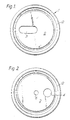
- Figure l shows a can end l having a substantially flat central portion 2 and an aperture 3 in the shape of a "race-track".
- Figure 2 shows a can end having an off-centre aperture 4 and a central aperture 5.
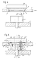
- Apparatus for orientating can ends such as those shown in Figures l and 2 is shown in Figures 3-5.
- Can ends are delivered from stacks thereof (not shown) to carrier plates 6 which transport the can ends to a moulding machine (not shown).
- the carrier plates shown each carry sixteen can ends in a 4 ⁇ 4 array.
- the carrier plates are provided with annular seats 7 for the can ends formed around openings 8 through the carrier plates.
- the seats are defined by a circular surface l3 which provides lateral restraint and an annular surface l4 extending radially inwards from the circular surface to provide axial support for the can ends.
- Three permanent magnets 9 are spaced around each seat to help locate the can ends and to prevent accidental displacement of the can ends from the seats and premature rotation during orientation.
- the magnets may be replaced by pads of material having a high coefficient of friction.
- the can ends are located with the surface l2 thereof, which will form the outer surface when the can end is fitted to a can, as the undersurface.
- the carriers 6 are transported on an indexing conveyor l0 to the orientating station ll shown in Figure 3.
- the conveyor comprises two parallel chains l5 with dogs l6 which engage the trailing edge of the carrier plates, the carriers being supported on guide rails (not shown).
- a table l7 mounted beneath the conveyor at the orientating station supports sixteen orientation heads l8. As shown more clearly in Figure 5, each head is mounted for roation on a shaft l9 and carries an eccentric peg 20 spring mounted in a cylindrical recess 2l in the body of the head. An annular shoulder 22 on the peg cooperates with a top plate 23 on each head to limit the displacement of the peg from its recess.
- each shaft l9 thereof is aligned with the central axis 25 of a respective can end and the central axis of each peg lies on a pitch circle which intersects the off-centre aperture in the can end such that the peg may seek, find and enter into the aperture when the necessary rotary alignment has taken place.
- the orientating table Prior to the arrival of a carrier plate 6 at the orientating station, the orientating table is mounted in a lower retracted position (shown in Figure 4) such that there is no engagement between the heads l8 and the carrier plate.
- the orientating table is moved upwardly to an operating position in which the pegs 20 resiliently engage the undersurfaces l2 of the can ends in the region of their central portions.
- the strength of the springs 24 is selected so as not to overcome the effect of the magnets 9 and displace the can ends from their seats.
- Guide rails 26 are, however, mounted over the can ends to restrict any such displacement.
- Orientation of the can ends is carried out as follows. Once the table has been raised to its operative position, the tips 27 of the pegs 20 will engage the can ends and will be pushed downwardly into their recesses 2l. Each head l8 is then rotated around the pitch circle through precisely one revolution. During this rotation the tip 27 will seek the aperture by wiping the undersurface of the can end until it locates and enters the off-centre aperture 3, thereafter causing the can end to rotate with it until rotation is stopped at the point of desired orientation. After rotation of the heads l8 through one revolution, the table is lowered to its retracted position and the carrier plate is conveyed to the moulding machine.
- the carrier plate is adapted to present the can ends in the chosen orientation to injection moulding apparatus which moulds a closure into the apertures.
- can ends having a race-track aperture 3 are shown in the drawings, it will be understood that all other can ends having off-centre apertures may be orientated in this manner.
- the shafts l9 are coupled together and connected to drive means comprising one or more single revolution clutches (not shown), for driving all the heads in rotation simultaneously and accurately through one revolution.
- drive means comprising one or more single revolution clutches (not shown), for driving all the heads in rotation simultaneously and accurately through one revolution.
- Alternative means to achieve a single revolution may be used, however, such as a controlled servo motor or a crank mechanism.
Landscapes
- Engineering & Computer Science (AREA)
- Mechanical Engineering (AREA)
- Specific Conveyance Elements (AREA)
- Closing Of Containers (AREA)
- Sealing Of Jars (AREA)
- Attitude Control For Articles On Conveyors (AREA)
- Spinning Or Twisting Of Yarns (AREA)
- Moulds For Moulding Plastics Or The Like (AREA)
- Medical Preparation Storing Or Oral Administration Devices (AREA)
Applications Claiming Priority (2)
| Application Number | Priority Date | Filing Date | Title |
|---|---|---|---|
| GB8617442 | 1986-07-17 | ||
| GB8617442A GB2192572B (en) | 1986-07-17 | 1986-07-17 | Method and apparatus for orientating can ends |
Publications (2)
| Publication Number | Publication Date |
|---|---|
| EP0258970A2 true EP0258970A2 (de) | 1988-03-09 |
| EP0258970A3 EP0258970A3 (de) | 1990-01-10 |
Family
ID=10601209
Family Applications (1)
| Application Number | Title | Priority Date | Filing Date |
|---|---|---|---|
| EP87305729A Withdrawn EP0258970A3 (de) | 1986-07-17 | 1987-06-26 | Verfahren und Vorrichtung zum Orientieren von Behälterenden |
Country Status (12)
| Country | Link |
|---|---|
| US (1) | US4776447A (de) |
| EP (1) | EP0258970A3 (de) |
| JP (1) | JPH062482B2 (de) |
| CN (1) | CN1005826B (de) |
| AU (1) | AU584514B2 (de) |
| BR (1) | BR8703651A (de) |
| CA (1) | CA1282366C (de) |
| GB (1) | GB2192572B (de) |
| NO (1) | NO165281C (de) |
| NZ (1) | NZ220951A (de) |
| SU (1) | SU1632368A3 (de) |
| ZA (1) | ZA874732B (de) |
Families Citing this family (12)
| Publication number | Priority date | Publication date | Assignee | Title |
|---|---|---|---|---|
| GB2198385B (en) * | 1986-12-05 | 1990-02-07 | Metal Box Plc | Apparatus for injection moulding |
| US5095681A (en) * | 1990-09-28 | 1992-03-17 | Plant Services Corp. | Fluid container capper apparatus |
| US5139132A (en) * | 1991-09-09 | 1992-08-18 | Ball Corporation | Orientation apparatus and method for disk shaped parts |
| JP3016171B2 (ja) * | 1993-04-06 | 2000-03-06 | 富士写真フイルム株式会社 | センターコアの移載方法及び装置 |
| AT407228B (de) * | 1997-02-13 | 2001-01-25 | Gomariz Perez Ana Maria | Vorrichtung zum nachlackieren von einschnitten in kreisförmigen schnellöffner-deckeln |
| CN201071392Y (zh) * | 2007-07-13 | 2008-06-11 | 富港电子(东莞)有限公司 | 连续式溅镀机工件输送装置 |
| ES2527928T3 (es) * | 2008-08-21 | 2015-02-02 | Ardagh Mp Group Netherlands B.V. | Tapa para un bote y método para orientar dicha tapa |
| CN102049449B (zh) * | 2010-10-29 | 2012-07-04 | 苏州华源包装股份有限公司 | 罐盖加工装置 |
| BR112017000032B1 (pt) | 2014-07-02 | 2021-10-13 | Doben Limited | Sistema de fixação e método de fabricar um conjunto |
| US10239109B2 (en) * | 2016-03-01 | 2019-03-26 | Stolle Machinery Company, Llc | Shell system locating assembly for shells |
| US10589338B1 (en) * | 2017-08-09 | 2020-03-17 | Thomas G. Kieran | Feed assembly for automated machines |
| CN118770734B (zh) * | 2024-08-23 | 2026-01-16 | 深圳市世宗自动化设备有限公司 | 来料纠偏装置 |
Family Cites Families (7)
| Publication number | Priority date | Publication date | Assignee | Title |
|---|---|---|---|---|
| US3163281A (en) * | 1961-08-21 | 1964-12-29 | Western Electric Co | Method and apparatus for handling articles |
| US3541751A (en) * | 1968-09-18 | 1970-11-24 | Illinois Tool Works | Method and apparatus for packaging a plurality of articles in predetermined arrangement |
| US3628650A (en) * | 1969-11-14 | 1971-12-21 | American Can Co | Apparatus for orienting can ends |
| US3993199A (en) * | 1975-05-05 | 1976-11-23 | Velasco Scale Company, Inc. | Filler-fitting alignment apparatus |
| GB1574226A (en) * | 1976-06-14 | 1980-09-03 | Styner & Bienz Ag | Method of producing a cover for a tin having a weakening scoring for tearing it open apparatus for carrying out this method and a cover produced in accordance with such method |
| DE2627381A1 (de) * | 1976-06-18 | 1977-12-29 | Illig Maschinenbau Adolf | Vorrichtung zum stapeln von kunststoffartikeln |
| GB2184080B (en) * | 1985-12-17 | 1988-12-14 | Metal Box Plc | Method and apparatus for orientating can ends |
-
1986
- 1986-07-17 GB GB8617442A patent/GB2192572B/en not_active Expired - Lifetime
-
1987
- 1987-06-26 EP EP87305729A patent/EP0258970A3/de not_active Withdrawn
- 1987-06-29 AU AU74925/87A patent/AU584514B2/en not_active Ceased
- 1987-06-30 ZA ZA874732A patent/ZA874732B/xx unknown
- 1987-07-03 NZ NZ220951A patent/NZ220951A/xx unknown
- 1987-07-14 BR BR8703651A patent/BR8703651A/pt unknown
- 1987-07-15 NO NO872951A patent/NO165281C/no unknown
- 1987-07-16 SU SU874203057A patent/SU1632368A3/ru active
- 1987-07-17 CA CA000542448A patent/CA1282366C/en not_active Expired - Lifetime
- 1987-07-17 JP JP17883287A patent/JPH062482B2/ja not_active Expired - Lifetime
- 1987-07-17 US US07/074,708 patent/US4776447A/en not_active Expired - Fee Related
- 1987-07-17 CN CN87104912.0A patent/CN1005826B/zh not_active Expired
Also Published As
| Publication number | Publication date |
|---|---|
| CA1282366C (en) | 1991-04-02 |
| NO872951D0 (no) | 1987-07-15 |
| GB2192572B (en) | 1990-04-04 |
| SU1632368A3 (ru) | 1991-02-28 |
| CN1005826B (zh) | 1989-11-22 |
| GB8617442D0 (en) | 1986-08-28 |
| BR8703651A (pt) | 1988-03-22 |
| JPH062482B2 (ja) | 1994-01-12 |
| NO165281B (no) | 1990-10-15 |
| NO872951L (no) | 1988-01-18 |
| EP0258970A3 (de) | 1990-01-10 |
| NO165281C (no) | 1991-01-23 |
| AU7492587A (en) | 1988-01-21 |
| AU584514B2 (en) | 1989-05-25 |
| ZA874732B (en) | 1988-01-07 |
| CN87104912A (zh) | 1988-05-18 |
| NZ220951A (en) | 1989-02-24 |
| US4776447A (en) | 1988-10-11 |
| JPS6333205A (ja) | 1988-02-12 |
| GB2192572A (en) | 1988-01-20 |
Similar Documents
| Publication | Publication Date | Title |
|---|---|---|
| US4776447A (en) | Method and apparatus for orientating can ends | |
| US5036569A (en) | Filter/funnel assembly machine | |
| US4158989A (en) | Constant flow container manufacturing device | |
| US4177548A (en) | Method and device for assembling coaxially interfitting parts | |
| EP1205388A1 (de) | Vorrichtung zur Steuerung der Drehbewegung von Gefässen | |
| EP0065866A1 (de) | Vorrichtung zum Ausrichten von Gegenständen wie Flaschen und Mittel zum Ausrichten | |
| RU2159181C2 (ru) | Термоформующее устройство для термоформуемых материалов в форме ленты или листа | |
| CN111002375B (zh) | 一种自动胶囊切割机 | |
| CN210306647U (zh) | 一种单向器全圆垫和罩盖自动化装配装置 | |
| US4567648A (en) | Rotary assembly machine | |
| EP0071393B1 (de) | Zuführvorrichtung für längliche Artikel | |
| US4485914A (en) | Variable drive pin projection mechanism for a belt sprocket drive wheel | |
| US4135618A (en) | Conveying apparatus | |
| CN111463387A (zh) | 一种锂电池防爆片及其自动压边设备和方法 | |
| US4271579A (en) | Paint roller cage assembly apparatus and method | |
| CA1110571A (en) | Tray indexing apparatus | |
| CN216097437U (zh) | 用于组装齿轮组件的转台机构以及组装装置 | |
| CN113453532B (zh) | 用于cob自动组装的传输装置 | |
| US4707945A (en) | Upper plate driving system for surface lapping machine | |
| CN217344353U (zh) | 一种喷雾盖组装设备 | |
| US2547551A (en) | Article feed device | |
| CN114190667A (zh) | 一种吊珠自动化生产线 | |
| CN116454708B (zh) | 一种换向器云母片组装工艺及设备 | |
| US4516447A (en) | Numerically controlled groove-stamping machine | |
| CN218967368U (zh) | 多工位封膜自动限位分隔装置 |
Legal Events
| Date | Code | Title | Description |
|---|---|---|---|
| PUAI | Public reference made under article 153(3) epc to a published international application that has entered the european phase |
Free format text: ORIGINAL CODE: 0009012 |
|
| 17P | Request for examination filed |
Effective date: 19870704 |
|
| AK | Designated contracting states |
Kind code of ref document: A2 Designated state(s): AT BE CH DE ES FR GB GR IT LI LU NL SE |
|
| RAP1 | Party data changed (applicant data changed or rights of an application transferred) |
Owner name: MB GROUP PLC |
|
| RAP1 | Party data changed (applicant data changed or rights of an application transferred) |
Owner name: CMB PACKAGING (UK) LIMITED |
|
| PUAL | Search report despatched |
Free format text: ORIGINAL CODE: 0009013 |
|
| AK | Designated contracting states |
Kind code of ref document: A3 Designated state(s): AT BE CH DE ES FR GB GR IT LI LU NL SE |
|
| RAP1 | Party data changed (applicant data changed or rights of an application transferred) |
Owner name: CMB FOODCAN PLC |
|
| 17Q | First examination report despatched |
Effective date: 19910308 |
|
| STAA | Information on the status of an ep patent application or granted ep patent |
Free format text: STATUS: THE APPLICATION HAS BEEN WITHDRAWN |
|
| 18W | Application withdrawn |
Withdrawal date: 19910218 |
|
| R18W | Application withdrawn (corrected) |
Effective date: 19910218 |
|
| RIN1 | Information on inventor provided before grant (corrected) |
Inventor name: PITCHER, TIMOTHY JAMES |