EP0258950A2 - Verfahren und Vorrichtung zum Anbringen von Füllrohren in Öffnungen von aus Folienmaterial hergestellten Flüssigkeitsbehältern - Google Patents
Verfahren und Vorrichtung zum Anbringen von Füllrohren in Öffnungen von aus Folienmaterial hergestellten Flüssigkeitsbehältern Download PDFInfo
- Publication number
- EP0258950A2 EP0258950A2 EP87201658A EP87201658A EP0258950A2 EP 0258950 A2 EP0258950 A2 EP 0258950A2 EP 87201658 A EP87201658 A EP 87201658A EP 87201658 A EP87201658 A EP 87201658A EP 0258950 A2 EP0258950 A2 EP 0258950A2
- Authority
- EP
- European Patent Office
- Prior art keywords
- guide
- rods
- rod
- passage
- containers
- Prior art date
- Legal status (The legal status is an assumption and is not a legal conclusion. Google has not performed a legal analysis and makes no representation as to the accuracy of the status listed.)
- Withdrawn
Links
- 239000011888 foil Substances 0.000 title claims abstract description 14
- 238000000034 method Methods 0.000 title claims abstract description 10
- 239000007788 liquid Substances 0.000 title claims abstract description 8
- 239000000463 material Substances 0.000 title claims abstract description 7
- 238000003780 insertion Methods 0.000 claims abstract description 20
- 230000037431 insertion Effects 0.000 claims abstract description 20
- 238000007789 sealing Methods 0.000 claims abstract description 10
- 238000001125 extrusion Methods 0.000 claims abstract description 8
- 229920003023 plastic Polymers 0.000 claims abstract description 8
- 239000004033 plastic Substances 0.000 claims abstract description 8
- 238000001746 injection moulding Methods 0.000 claims abstract description 4
- 239000007787 solid Substances 0.000 claims abstract description 3
- 210000000078 claw Anatomy 0.000 claims description 8
- 238000006073 displacement reaction Methods 0.000 claims description 4
- 238000005304 joining Methods 0.000 claims description 4
- 238000003825 pressing Methods 0.000 claims description 3
- 230000000717 retained effect Effects 0.000 claims description 3
- 238000007599 discharging Methods 0.000 claims description 2
- 238000005520 cutting process Methods 0.000 description 4
- 238000004519 manufacturing process Methods 0.000 description 4
- 230000035622 drinking Effects 0.000 description 3
- 239000003889 eye drop Substances 0.000 description 3
- 239000010902 straw Substances 0.000 description 3
- 239000006196 drop Substances 0.000 description 2
- 239000008267 milk Substances 0.000 description 2
- 210000004080 milk Anatomy 0.000 description 2
- 235000013336 milk Nutrition 0.000 description 2
- 241000542420 Sphyrna tudes Species 0.000 description 1
- 230000007812 deficiency Effects 0.000 description 1
- 230000000694 effects Effects 0.000 description 1
- 229940012356 eye drops Drugs 0.000 description 1
- 230000002349 favourable effect Effects 0.000 description 1
- 239000007924 injection Substances 0.000 description 1
- 238000002347 injection Methods 0.000 description 1
- 230000007246 mechanism Effects 0.000 description 1
- 238000005482 strain hardening Methods 0.000 description 1
- 239000011345 viscous material Substances 0.000 description 1
- 238000004804 winding Methods 0.000 description 1
Images

Classifications
-
- B—PERFORMING OPERATIONS; TRANSPORTING
- B31—MAKING ARTICLES OF PAPER, CARDBOARD OR MATERIAL WORKED IN A MANNER ANALOGOUS TO PAPER; WORKING PAPER, CARDBOARD OR MATERIAL WORKED IN A MANNER ANALOGOUS TO PAPER
- B31B—MAKING CONTAINERS OF PAPER, CARDBOARD OR MATERIAL WORKED IN A MANNER ANALOGOUS TO PAPER
- B31B50/00—Making rigid or semi-rigid containers, e.g. boxes or cartons
-
- B—PERFORMING OPERATIONS; TRANSPORTING
- B31—MAKING ARTICLES OF PAPER, CARDBOARD OR MATERIAL WORKED IN A MANNER ANALOGOUS TO PAPER; WORKING PAPER, CARDBOARD OR MATERIAL WORKED IN A MANNER ANALOGOUS TO PAPER
- B31B—MAKING CONTAINERS OF PAPER, CARDBOARD OR MATERIAL WORKED IN A MANNER ANALOGOUS TO PAPER
- B31B70/00—Making flexible containers, e.g. envelopes or bags
- B31B70/74—Auxiliary operations
- B31B70/81—Forming or attaching accessories, e.g. opening devices, closures or tear strings
- B31B70/84—Forming or attaching means for filling or dispensing contents, e.g. valves or spouts
- B31B70/844—Applying rigid valves, spouts, or filling tubes
-
- B—PERFORMING OPERATIONS; TRANSPORTING
- B31—MAKING ARTICLES OF PAPER, CARDBOARD OR MATERIAL WORKED IN A MANNER ANALOGOUS TO PAPER; WORKING PAPER, CARDBOARD OR MATERIAL WORKED IN A MANNER ANALOGOUS TO PAPER
- B31B—MAKING CONTAINERS OF PAPER, CARDBOARD OR MATERIAL WORKED IN A MANNER ANALOGOUS TO PAPER
- B31B50/00—Making rigid or semi-rigid containers, e.g. boxes or cartons
- B31B50/74—Auxiliary operations
- B31B50/81—Forming or attaching accessories, e.g. opening devices, closures or tear strings
- B31B50/84—Forming or attaching means for filling or dispensing contents, e.g. valves or spouts
Definitions
- the invention relates to a method for applying solid or hollow plastics filling rods in apertures in sealing seams of intermittently transported liquid containers consisting of foil material or not yet completely sealed shaped foil webs for forming such containers, said rods being inserted by means of an insertion guide which is movable transversely to the line of transport and is provided with a longitudinal cavity, into said apertures, and, after insertion, said rods are secured in said apertures by means of heated shoes, and are locally deformed thereby; the invention further relates to a device for executing said method.
- Such a method and device are known from DE-C 2 310 787 for applying threads in dispensing containers for eye drops.
- a thin plastics thread is unwound from a coil and is propulsed in said insertion guide over a given length,and, by translating said guide, is driven into an aperture of a container, after which a cutting knife included in said guide cuts off the thread.
- the pieces of wire forming said rods are injection moulded or are, shortly after leaving an extrusion press, cut at the required length as is also done when manufacturing drinking straws, so that said rods are not being stretched and remain, moreover, straight.
- the draw-backs of the known methods can be avoided, and also in the case of rods having a larger diameter a good clamping can be obtained without damaging the foil material of the containers. This is of great importance in the case of larger containers intended for dispensing milk or more viscous liquids, and in which substantially thicker filling rods are to be used than in the case of eye drop containers.
- the device according to the invention is characterised by a vibrating drum for lining up and discharging the aligned filling rods towards the insertion guide joining the discharge end of said drum, said guide having a longitudinal cavity in which rods introduced at one extremity thereof can be guided in succession, said guide being provided with a friction clamp by means of which the lowermost rod can be retained, and by driving means by means of which,before or during the longitudinal displacement of the guide towards the transport line, a plurality of rods bearing on the lowermost rod can be shifted onwards in order to drive the lowermost rod outwards through said clamp, and, when retracting said guide, a next rod is being moved towards the starting position, all this in such a manner that said guide is only being retracted after the shoes have become operative.
- this device is characterised in that said guide comprises a clamping assembly having a set of out wardly resilient claws, said claws, when moving the guide towards the transport line, are being clamped by wedge action against the rod present in its cavity, said claws being released when retracting the guide so as to allow the next rods to slide onwards, stops being provided for actuating the clamping assembly when the guide is being moved.
- the insertion guide can comprise a slide which is movable transversely to the axis of the guide, said slide being provided with a bore adapted to be aligned with the passage of the guide, and, on the other hand, can be placed in alignment with another passage communicating with the outlet end of said vibrating drum, said slide having the height of a rod, all this in such a manner that, on shifting said slide, always one rod can be supplied to the former passage, and a pressing finger to be inserted into said passage can be used, which is adapted to shift the rods present in said passage over a distrance which is smaller than the height of a rod.
- the friction clamp at the discharge end of said passage is, in particular, an O-ring.
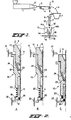
- Fig. 1 shows a highly simplified representation of a device according to the invention.
- This device comprises an extrusion press 1 with a nozzle 2 for forming a plastics thread 3, a discharge belt 4 and a cutting tool 5 for cutting the thread 3 into rods 6, which, as such, do not form a part of the device according to the invention, but are shown for indicating how the rods 6 intended for the present purpose can be made.
- a core 2' is provided in the nozzle 2.
- Such an extrusion device is of the known kind used for forming plastics thread or plastics drinking straws, but differs from a thread extrusion press in that no stretching and winding rollers are present, and from a drinking straw press in that the cutting tool 4 is adjusted at the desired small length.
- the nozzle 2 is adapted to the desired diameter of the rods, which for liquid containers can be about 1,5 mm, but can be larger for containers for viscous substances.
- the diameter of the bore thereof should, of course, be adapted to the intended use, and, in view of the further processing to be described below, it is advisable to use always a fixed outer diameter.
- the rods 6 are poured in a vibrating drum 7 belonging to the device of the invention proper, in which drum, by vibration, the rods 6 are lined up in succession in a discharge gutter 8.
- a vibrating drum 7 belonging to the device of the invention proper, in which drum, by vibration, the rods 6 are lined up in succession in a discharge gutter 8.
- Such vibrating drums are generally known, and, therefore, need not be described in more detail.
- the discharge gutter 8 ends above a filling funnel 9 of a diagrammatically indicated and vertically arranged insertion guide 10 which is provided with a longitudinal passage 11, in which the introduced rods are positioned in succession in a row.
- the dispensing opening 12 at the lower end of this guide is directed towards a transport line 13, shown in a highly diagrammatic way, for not yet completed liquid containers 14c consisting of plastics foil webs 14a and 14b, which can be translated stepwise in such a manner that, when stationary, the dispensing opening 12 of the guide 10 can be positioned precisely in front of a passage 14 in an already formed sealing seam between the foils 14a and 14b.
- the rod 6 When translating the guide 10 in the longitudinal direction, the rod 6 being shifted outwards through the dispensing opening 12 in a manner to be described can be inserted into the passage 15, after which, by pressing heated shoes 16, said rod can be clasped in the sealing seam, and is, then, somewhat compressed, so that it is unambiguously anchored therein. After retracting the guide 10, the rod 6 remains in the opening 15, and the guide can then be used for a subsequent insertion operation.
- a transport line for moving the foil webs 14a and 14b is known from DE-C 2 310 787, and, therefore, needs not to be described in detail.
- This known device is adapted to manufacturing small eye drop containers, but the present device is, in particular but not exclusively, intended for manufacturing larger dispensing containers, more in particular for milk and the like, but this does not change anything in the fundamental concept of such a transport line.
- FIG. 2 diagrammatic sections of an embodiment of the insertion guide 10 of Fig. 1 are shown in three consecutive operational positions. The operation of this insertion guide is substantially the same as in the case of a push-button pencil.
- the guide 10 shown consists, now, of three mutually shiftable coaxial main parts, viz. a clamping and driving piece 17 provided with the filling funnel 9 or joining the latter, a casing 18, and a dispensing terminal piece 19 with the dispensing opening 12, which parts define the passage 11. Between the parts 18 and 19 a coil spring 20 is provided.
- This guide cooperates with two fixed stops 21 and 22 arranged in suitable points along the displacement line of the guide 10, which are, for the sake of simplicity, shown here close to one another.
- the clamping piece 17 is connected with a driving means not shown for reciprocating said piece, but, for the upward displacement, also a spring can be used.
- the guide 10 After fixing the lowermost rod in the opening 15 of a container 14, the guide 10 is retracted, and the remainder of the fixed rod is extracted from the 0-ring. After arresting the casing 18 by the stop 21, the springs 23 are released, and the rod 6 can shift downwards until the lowermost rod abuts the 0-ring 25.
- this guide can be modified in many ways.
- the terminal piece 19 can be a part of the casing 18, and the driving means can be made so that, at first, a rod 6' is pressed outwards before the guide 10 is shifted.
- a claw engaging the collar of the casing 18 can be used, which can move along when the clamping piece 17 is pressed downwards, thus taking over the tasks of the stops 21 and 22.
- a number of spring blades can be provided, and also other, and in particular double, claw mechanisms can be used with the same effect.
- FIG. 3 an other embodiment of the guide 10 is shown, which is constructed as a plural guide for simulataneously inserting a number of rods 6.
- This guide 10 comprises a number of passages 11, each joined by a dispensing nozzle 19'.
- a supply slide 26 with bores 27 is arranged, which bores can be aligned with the passages 11, and have a height which equals the length of the rods 6. If the slide 26 is moved to the left, said bores 27 can be placed below corresponding passages 28, each joining the discharge gutter of a vibrating drum 7 according to Fig. 1.
- a rod 6 can drop, then, into the corresponding bore 27, and will drop into the corresponding passage 11 after shifting the slide 26 to the right.
- a pressure finger 29 can be inserted, which, when pressed downwards, will shift downwards the underlying string of rods 6 over, for instance, half the height of a rod 6.
- a subsequent rod can fall upon the string already present.
Landscapes
- Basic Packing Technique (AREA)
- Auxiliary Devices For And Details Of Packaging Control (AREA)
- Filling Or Emptying Of Bunkers, Hoppers, And Tanks (AREA)
Applications Claiming Priority (2)
| Application Number | Priority Date | Filing Date | Title |
|---|---|---|---|
| NL8602209A NL8602209A (nl) | 1986-09-01 | 1986-09-01 | Werkwijze en inrichting voor het aanbrengen van vulstaafjes in openingen van vloeistofhouders uit foeliemateriaal. |
| NL8602209 | 1986-09-01 |
Publications (2)
| Publication Number | Publication Date |
|---|---|
| EP0258950A2 true EP0258950A2 (de) | 1988-03-09 |
| EP0258950A3 EP0258950A3 (de) | 1990-07-11 |
Family
ID=19848483
Family Applications (1)
| Application Number | Title | Priority Date | Filing Date |
|---|---|---|---|
| EP87201658A Withdrawn EP0258950A3 (de) | 1986-09-01 | 1987-09-01 | Verfahren und Vorrichtung zum Anbringen von Füllrohren in Öffnungen von aus Folienmaterial hergestellten Flüssigkeitsbehältern |
Country Status (2)
| Country | Link |
|---|---|
| EP (1) | EP0258950A3 (de) |
| NL (1) | NL8602209A (de) |
Family Cites Families (6)
| Publication number | Priority date | Publication date | Assignee | Title |
|---|---|---|---|---|
| FR1291649A (fr) * | 1961-03-15 | 1962-04-27 | Seab | Dispositif de positionnement et de soudage d'embases d'obturateurs sur une gaine plastique |
| NL6905332A (en) * | 1969-04-03 | 1970-10-06 | Plastics tube production | |
| NL6905331A (en) * | 1969-04-03 | 1970-10-06 | Plastic tubes | |
| DE2310787C2 (de) * | 1973-03-03 | 1982-03-25 | Dr. Karl Thomae Gmbh, 7950 Biberach | Verfahren und Vorrichtung zur Herstellung von Eindosenbehältern mit Öffnungsfäden |
| FR2225351B1 (de) * | 1973-04-10 | 1978-10-27 | Thimonnier & Cie | |
| US4475435A (en) * | 1983-02-25 | 1984-10-09 | Mantel Machine Products, Inc. | In line bullet feeder |
-
1986
- 1986-09-01 NL NL8602209A patent/NL8602209A/nl not_active Application Discontinuation
-
1987
- 1987-09-01 EP EP87201658A patent/EP0258950A3/de not_active Withdrawn
Also Published As
| Publication number | Publication date |
|---|---|
| NL8602209A (nl) | 1988-04-05 |
| EP0258950A3 (de) | 1990-07-11 |
Similar Documents
| Publication | Publication Date | Title |
|---|---|---|
| US4091595A (en) | Netting bag machine and method | |
| DE69213337T2 (de) | Vorrichtung vom vertikalen Typ, zum Formen, Füllen und Schliessen von flexiblen Verpackungen | |
| KR940007857B1 (ko) | 드립 용수 도관의 제조 장치 및 방법 | |
| US4118162A (en) | Apparatus for manufacturing lengths of rubber hose of curved shape | |
| DE19838076A1 (de) | Verfahren und Vorrichtung zum Herstellen von (Groß-)Packungen | |
| JPH06209993A (ja) | ドリップ灌注装置を作る方法及び装置 | |
| US4111491A (en) | Method and apparatus for feeding bristles in brush making machines | |
| US4110956A (en) | Apparatus for forming, filling and sealing bags made from flattened plastic tubular plastic stock | |
| US4155296A (en) | Method of binding pressed bales and baling press for carrying out the method | |
| EP0015529B1 (de) | Etikettiervorrichtung | |
| EP0258950A2 (de) | Verfahren und Vorrichtung zum Anbringen von Füllrohren in Öffnungen von aus Folienmaterial hergestellten Flüssigkeitsbehältern | |
| EP0054388A2 (de) | Verfahren und Vorrichtung zur Rückgewinnung von Kunststoffabfällen | |
| US6996954B1 (en) | Horizontal sleeve applicator and method | |
| DE2065534A1 (de) | Vorrichtung zum durchschneiden von folienbahnen | |
| CA1156181A (en) | Method and apparatus for feeding conductive wire for anodizing process of slide fastener chain | |
| EP0513439A1 (de) | Vorrichtung zum Füllen und Verschliessen von Fliessmittelpackungen | |
| US9265264B2 (en) | Clipping machine with improved handling of suspension elements | |
| DE2262951A1 (de) | Vorrichtung zum einlegen von laenglichen gegenstaenden | |
| EP0482435A2 (de) | Verfahren und Vorrichtung zum Feststellen der Lage eines Markier- oder Trennelementes in einem Stapel von flächigen Erzeugenissen | |
| WO2016146273A1 (de) | Vorrichtung und verfahren zum perforieren eines folienschlauchs und zum etiketieren von flaschen | |
| US3818676A (en) | Packaging machines | |
| EP4480838A1 (de) | Vorrichtung zum bereitstellen einer zweikammerverpackung sowie zweikammerverpackung | |
| EP0053864A1 (de) | Verfahren und Einrichtung zum voneinander Scheiden zweier dünner, schlapper Folien | |
| US6854811B2 (en) | Method for producing a brush | |
| DE19519591C2 (de) | Vorrichtung zum Herstellen von gefüllten verschlossenen Schlauchbeutelpackungen |
Legal Events
| Date | Code | Title | Description |
|---|---|---|---|
| PUAI | Public reference made under article 153(3) epc to a published international application that has entered the european phase |
Free format text: ORIGINAL CODE: 0009012 |
|
| AK | Designated contracting states |
Kind code of ref document: A2 Designated state(s): AT BE CH DE ES FR GB GR IT LI LU NL SE |
|
| 17P | Request for examination filed |
Effective date: 19880917 |
|
| PUAL | Search report despatched |
Free format text: ORIGINAL CODE: 0009013 |
|
| AK | Designated contracting states |
Kind code of ref document: A3 Designated state(s): AT BE CH DE ES FR GB GR IT LI LU NL SE |
|
| 17Q | First examination report despatched |
Effective date: 19910612 |
|
| STAA | Information on the status of an ep patent application or granted ep patent |
Free format text: STATUS: THE APPLICATION IS DEEMED TO BE WITHDRAWN |
|
| 18D | Application deemed to be withdrawn |
Effective date: 19911023 |
|
| RIN1 | Information on inventor provided before grant (corrected) |
Inventor name: HEIJENGA, BEREND |