EP0257871A2 - Maschine zum Anbringen von Knöpfen - Google Patents
Maschine zum Anbringen von Knöpfen Download PDFInfo
- Publication number
- EP0257871A2 EP0257871A2 EP87306953A EP87306953A EP0257871A2 EP 0257871 A2 EP0257871 A2 EP 0257871A2 EP 87306953 A EP87306953 A EP 87306953A EP 87306953 A EP87306953 A EP 87306953A EP 0257871 A2 EP0257871 A2 EP 0257871A2
- Authority
- EP
- European Patent Office
- Prior art keywords
- punch
- button
- holder
- unit
- Prior art date
- Legal status (The legal status is an assumption and is not a legal conclusion. Google has not performed a legal analysis and makes no representation as to the accuracy of the status listed.)
- Withdrawn
Links
Images


Classifications
-
- A—HUMAN NECESSITIES
- A44—HABERDASHERY; JEWELLERY
- A44B—BUTTONS, PINS, BUCKLES, SLIDE FASTENERS, OR THE LIKE
- A44B1/00—Buttons
-
- A—HUMAN NECESSITIES
- A41—WEARING APPAREL
- A41H—APPLIANCES OR METHODS FOR MAKING CLOTHES, e.g. FOR DRESS-MAKING OR FOR TAILORING, NOT OTHERWISE PROVIDED FOR
- A41H37/00—Machines, appliances or methods for setting fastener-elements on garments
- A41H37/10—Setting buttons
Definitions
- the present invention relates to an apparatus for attaching buttons to a garment fabric, and more particularly a punch/holder unit for use in such attaching apparatus.
- buttons of a tiltable type to a substrate such as a garment fabric.
- the button has a button head loosely or tiltably mounted on a hub member and a tack member to be inserted into the hub.
- the tack member is clenched to deform by a punch acting directly on the pointed end of the tack through an aperture in the button head.
- the apparatus includes an integral punch/holder unit for holding therein the tiltable button with its integral punch disposed in the aperture of the button.
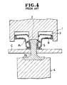
- FIG. 4 of the accompanying drawings shows an example of such known punch/holder unit, in which the tiltable button Pl is joined with the tack member P2 which underlies a sheet of fabric C. More specifically, the integral punch/holder unit l holding the tiltable button Pl is moved downwardly by a suitable drive means toward the tack member P2 supported on the die unit 4, until the pointed end of the tack member P2 begins to penetrate the fabric C set in place between the upper unit l and the lower unit 4, and moves into the hub member S of the button. During this movement of the tack member P2 relative to the button Pl, the punch 2 squeezes the pointed end of the tack member to deform radially outwardly as shown in Figure 4.
- Such prior art apparatus has a drawback in that the button Pl would often fail to tilt due to such deformation of the hub member S as depicted in solid line which is caused by premature deformation of the tack in the hub member initially disposed in the position shown by a phantom line in Figure 4, in which the inner wall of the hub member is forced radially outwardly.
- premature deformation is meant that the punch 2 begins to crush the pointed end of the tack member P2 before it is fully inserted into the hub member S on account of the fact that the punch and the button holder are built integral.
- the present invention seeks to provide an apparatus for attaching a tiltable button with a tack member without impairing the tilting function of the button.
- a punch/holder unit in cooperation with a die unit for joining a tiltable button having a head aperture with a tack member for attachment to a fabric, said button having a hub member and a button head tiltably mounted on the hub member, said punch/holder unit comprising: a punch unit including a punch and a base integrally secured to said punch and operatively connected to an actuator ram so as to reciprocate said punch; a button holder including a holder body defining a pocket for receiving the tiltable button, said holder having a guide defining therein a guide channel communicating with said pocket, in which channel said punch is reciprocably movable; and a compression spring extending between and secured to said base of said punch and said holder for normally urging said holder downwardly away from said punch.
- An apparatus for attaching a tiltable button Pl with a tack member P2 to a fabric C includes an upper or punch/holder unit l0 and a lower or die unit 4 as shown in Figure 2.
- the punch/holder unit is suitable for use in applying a tiltable button to a mating tack across a substrate such as a garment fabric.
- the button has a hub member S and a button head B tiltably or loosely mounted thereon.
- the button head has a central aperture formed on its top.
- the upper unit includes a punch unit l2 and a button holder l3 physically separated from but functionally associated with each other.
- the punch unit l2 is operatively connected to a vertically movable ram ll which is in turn connected to a drive (not shown).
- the punch unit l2 includes a base l4 secured by a screw l6 to the ram ll, and a punch l5 extending integrally from the base l4.
- the punch l5 is in the form of a cylindrical rod and has a recessed or concaved lower end l7.
- the button holder l3 is disposed beneath the punch unit l2 and includes a holder body l8 for holding therein the tiltable button.
- the holder body l8 has a horizontal circular wall and an annular peripheral wall extending circumferentially of the circular wall, thereby defining a pocket or space 20 downwardly opening for receiving the tiltable button Pl ( Figure 2).
- the button holder l3 also includes a guide l9 extending coaxially upwardly from the circular wall of the holder body l8.
- the guide l9 and the circular wall jointly define a guide channel 23 extending vertically therethrough as shown in Figure l, in which channel the punch l5 is reciprocably movable.
- the button holder l3 further includes a pair of stoppers 22 loosely received respectively in guide pits or cavities 23 formed in the peripheral wall of the holder body l8.
- the guide pits 23 are disposed diametrically opposite to each other and each have a reduced-diameter bore opening into the pocket 20.
- the stopper 22 is loosely fit in the guide pit 23 and movable through the reduced-diameter bore of the guide pit 23 to protrude into the pocket 20 to an extent controlled.
- a coiled spring 24 extends throughout the circumference of the peripheral wall of the holder body l8, more specifically in and along an annular groove in the peripheral wall, such that the spring 24 normally urges the stoppers 22 to protrude into the pocket 20.
- two of these stoppers are provided but more of them may be provided at uniformly spaced angular intervals.
- the punch unit l2 and the button holder l3 are resiliently connected to each other by a compression spring 25 extending between the base l4 of the punch unit and the button holder and connected to them at the opposite ends.
- the compression spring 25 normally urges the button holder l3 to move relatively away from the punch unit l2, more specifically, the pocket 20 to move away from the recessed lower end l7 of the punch l5 or vice versa.
- the punch/holder unit l0 is in an uppermost or initial position where the lower end l7 of the punch l5 is held away from the pocket 20 under the force of the compression spring 25.
- the tiltable button Pl is set in place in the pocket 20 while the tack member P2 is set in place on the die unit 4.
- the holding of the button Pl by the button holder l3 is assured by the asistance of the stoppers 22, 22 which resiliently abut and engage sidewardly with the button head.
- the fabric C to which the button Pl is to be attached is placed between the tiltable button Pl and the tack member P2.
- the ram ll is actuated by means not shown to downwardly move the punch/holder unit l0, i.e. the punch unit l2 and the button holder l3 together, until the tack member P2 thrusts through the fabric C fully into the hub of the button Pl as shown in Figure 2, in which instance the concaved lower end l7 of the punch l5 is held still remotely from the pocket 20.
- the punch l5 With continued downward movement of the ram ll, the punch l5 begins to move downwardly in the guide channel 2l relative to the button holder l3 against the force of the compression spring 25.
- the punch l5 presses against the pointed end of the tack member P2 positioned in the central aperture of the button Pl and compresses the same at its concaved end l7 thereby deforming the pointed end into a radially outwardly bulged shape as shown in Figure 3. Consequently, the tiltable button Pl is jointed with the tack member P2 on the fabric C.
- the punch l5 acts on the pointed end of the tack member P2 only after the latter has been fully inserted into the button Pl so that the pointed end of the tack member P2 is compressed to deform exteriorly of the hub of the button Pl, thereby avoiding an undesirable deformation of the hub member S which deformation would causes a mulfunction of the tiltable button.
Landscapes
- Engineering & Computer Science (AREA)
- Textile Engineering (AREA)
- Labeling Devices (AREA)
- Sewing Machines And Sewing (AREA)
- Slide Fasteners, Snap Fasteners, And Hook Fasteners (AREA)
- Clamps And Clips (AREA)
- Vehicle Step Arrangements And Article Storage (AREA)
Applications Claiming Priority (2)
| Application Number | Priority Date | Filing Date | Title |
|---|---|---|---|
| JP119981/86U | 1986-08-05 | ||
| JP1986119981U JPH0311211Y2 (de) | 1986-08-05 | 1986-08-05 |
Publications (2)
| Publication Number | Publication Date |
|---|---|
| EP0257871A2 true EP0257871A2 (de) | 1988-03-02 |
| EP0257871A3 EP0257871A3 (de) | 1988-08-03 |
Family
ID=14774955
Family Applications (1)
| Application Number | Title | Priority Date | Filing Date |
|---|---|---|---|
| EP87306953A Withdrawn EP0257871A3 (de) | 1986-08-05 | 1987-08-05 | Maschine zum Anbringen von Knöpfen |
Country Status (5)
| Country | Link |
|---|---|
| EP (1) | EP0257871A3 (de) |
| JP (1) | JPH0311211Y2 (de) |
| KR (1) | KR890001800Y1 (de) |
| AU (1) | AU573135B2 (de) |
| MY (1) | MY101004A (de) |
Citations (4)
| Publication number | Priority date | Publication date | Assignee | Title |
|---|---|---|---|---|
| US2310008A (en) * | 1939-05-16 | 1943-02-02 | Scovill Manufacturing Co | Apparatus for setting buttons and the like |
| CH432987A (de) * | 1965-02-17 | 1967-03-31 | Alexander Brero Ag | Als Fangstempel ausgebildeter Nietstempel für Druckknopfpressen |
| GB2065448A (en) * | 1979-12-13 | 1981-07-01 | Yoshida Kogyo Kk | Apparatus for attaching fastener elements onto a garment |
| AU556534B2 (en) * | 1982-06-29 | 1986-11-06 | W.A. Deutsher Pty Ltd | Snap fastener |
Family Cites Families (3)
| Publication number | Priority date | Publication date | Assignee | Title |
|---|---|---|---|---|
| GB2147239B (en) * | 1983-09-19 | 1986-08-13 | Nippon Notion Kogyo | Apparatus for attaching pairs of fastener elements onto garment fabrics |
| JPS6063524U (ja) * | 1983-10-04 | 1985-05-04 | 日本ノーシヨン工業株式会社 | 釦加工装置の部品支持装置 |
| JPH0232650Y2 (de) * | 1985-07-10 | 1990-09-04 |
-
1986
- 1986-08-05 JP JP1986119981U patent/JPH0311211Y2/ja not_active Expired
-
1987
- 1987-07-24 AU AU76076/87A patent/AU573135B2/en not_active Ceased
- 1987-07-31 KR KR2019870012795U patent/KR890001800Y1/ko not_active IP Right Cessation
- 1987-08-01 MY MYPI87001194A patent/MY101004A/en unknown
- 1987-08-05 EP EP87306953A patent/EP0257871A3/de not_active Withdrawn
Patent Citations (4)
| Publication number | Priority date | Publication date | Assignee | Title |
|---|---|---|---|---|
| US2310008A (en) * | 1939-05-16 | 1943-02-02 | Scovill Manufacturing Co | Apparatus for setting buttons and the like |
| CH432987A (de) * | 1965-02-17 | 1967-03-31 | Alexander Brero Ag | Als Fangstempel ausgebildeter Nietstempel für Druckknopfpressen |
| GB2065448A (en) * | 1979-12-13 | 1981-07-01 | Yoshida Kogyo Kk | Apparatus for attaching fastener elements onto a garment |
| AU556534B2 (en) * | 1982-06-29 | 1986-11-06 | W.A. Deutsher Pty Ltd | Snap fastener |
Also Published As
| Publication number | Publication date |
|---|---|
| EP0257871A3 (de) | 1988-08-03 |
| AU7607687A (en) | 1988-02-11 |
| JPS6327434U (de) | 1988-02-23 |
| AU573135B2 (en) | 1988-05-26 |
| JPH0311211Y2 (de) | 1991-03-19 |
| MY101004A (en) | 1991-06-29 |
| KR890001800Y1 (ko) | 1989-04-08 |
| KR880003977U (ko) | 1988-05-06 |
Similar Documents
| Publication | Publication Date | Title |
|---|---|---|
| EP0643633B1 (de) | Verfahren zum verbinden von zwei oder mehreren aufeinanderliegenden blechen und eine vorrichtung zur durchführung dieses verfahrens | |
| GB2152415A (en) | Attaching a female element to a panel | |
| US4436238A (en) | Apparatus for attaching fastener elements onto a garment | |
| US20180172055A1 (en) | Method for the connection of sheet metal parts and component assembly as well as setting head and die button | |
| US20060039777A1 (en) | Stamped rivet for connection to sheet metals and method for placing said stamped rivet | |
| JPS63260631A (ja) | バ−リング成形装置 | |
| US3526943A (en) | Tool head assembly | |
| GB2150249A (en) | Apparatus for assembling a pair of fastener elements | |
| EP0257871A2 (de) | Maschine zum Anbringen von Knöpfen | |
| US20060010671A1 (en) | Device for placing a stamped rivet in sheet metal | |
| US3795036A (en) | Die-set combination for making pin-back badges | |
| US3357084A (en) | Machine for assembling members and providing a controlled amount of tolerance between the members | |
| WO2013118262A1 (ja) | ボタン取付装置及びボタン保持ダイ | |
| US4782559A (en) | Button collet and method and apparatus for making the same | |
| GB2055648A (en) | Apparatus for applying a nut to a workpiece | |
| US2361688A (en) | Method and apparatus for installing fasteners | |
| US4962875A (en) | Parts applying apparatus | |
| US3942225A (en) | Supporting button for articles of luggage, etc. | |
| JPH05192717A (ja) | 金型ストリップミス防止方法 | |
| JPH0655376A (ja) | ピアスナット自動組立装置 | |
| US2932073A (en) | Fastening device | |
| US5150525A (en) | Drawing device for use in drafting machine | |
| EP0136633B1 (de) | Vorrichtung zum Ansetzen von Verschlussteilhälften | |
| EP0212675B1 (de) | Vorrichtung zur Wegnahme von Kleidungsverschlusselementen | |
| US3479727A (en) | Riveting |
Legal Events
| Date | Code | Title | Description |
|---|---|---|---|
| PUAI | Public reference made under article 153(3) epc to a published international application that has entered the european phase |
Free format text: ORIGINAL CODE: 0009012 |
|
| AK | Designated contracting states |
Kind code of ref document: A2 Designated state(s): DE FR GB IT |
|
| PUAL | Search report despatched |
Free format text: ORIGINAL CODE: 0009013 |
|
| AK | Designated contracting states |
Kind code of ref document: A3 Designated state(s): DE FR GB IT |
|
| 17P | Request for examination filed |
Effective date: 19880607 |
|
| 17Q | First examination report despatched |
Effective date: 19891009 |
|
| STAA | Information on the status of an ep patent application or granted ep patent |
Free format text: STATUS: THE APPLICATION IS DEEMED TO BE WITHDRAWN |
|
| 18D | Application deemed to be withdrawn |
Effective date: 19900629 |
|
| RIN1 | Information on inventor provided before grant (corrected) |
Inventor name: ITO, KAZUYOSHI |