EP0257707A2 - Méthode pour contrôler le déroulement de la chaîne et l'enroulement du tissu dans les métiers à tisser - Google Patents
Méthode pour contrôler le déroulement de la chaîne et l'enroulement du tissu dans les métiers à tisser Download PDFInfo
- Publication number
- EP0257707A2 EP0257707A2 EP87201562A EP87201562A EP0257707A2 EP 0257707 A2 EP0257707 A2 EP 0257707A2 EP 87201562 A EP87201562 A EP 87201562A EP 87201562 A EP87201562 A EP 87201562A EP 0257707 A2 EP0257707 A2 EP 0257707A2
- Authority
- EP
- European Patent Office
- Prior art keywords
- warp
- characteristic
- period
- weave pattern
- detected signal
- Prior art date
- Legal status (The legal status is an assumption and is not a legal conclusion. Google has not performed a legal analysis and makes no representation as to the accuracy of the status listed.)
- Withdrawn
Links
Images

Classifications
-
- D—TEXTILES; PAPER
- D03—WEAVING
- D03D—WOVEN FABRICS; METHODS OF WEAVING; LOOMS
- D03D49/00—Details or constructional features not specially adapted for looms of a particular type
- D03D49/04—Control of the tension in warp or cloth
-
- D—TEXTILES; PAPER
- D03—WEAVING
- D03D—WOVEN FABRICS; METHODS OF WEAVING; LOOMS
- D03D49/00—Details or constructional features not specially adapted for looms of a particular type
- D03D49/04—Control of the tension in warp or cloth
- D03D49/06—Warp let-off mechanisms
Definitions
- This invention concerns a method for controlling the warp le.t-off and cloth take-up motions on weaving machines, and in particular a method of processing the associated control signals so that they are not affected by the weaving pattern.
- textile quality depends to a large extent on the tension and speed of motion of the warp threads during weaving.
- the speed of motion of the warp threads depends on the speed of motion of the cloth, which in turn depends on the operating speed of the weaving machine.
- the difference between the speed of motion of the warp threads and the cloth respectively is dependent on the interweaving. Normally, all measures are of course taken to control the warp thread speed so that the tension in the warp threads is kept as constant as possible.
- the instantaneous tension is measured and used to control the warp let-off.
- the instantaneous speed of the weaving machine drive motor is measured and used to control the warp let-off.
- this method of operation has the disadvantage that the control system reacts to all disturbance signals, even although compensation is not necessary for disturbance signals of very short duration, since these tend to be self-compensating. If a compensation function is nevertheless generated, there is a risk of overcompensation, with all the attendant disadvantages for the quality of the textile.
- the main disturbance signals for which the control system does not need to provide compensation are the periodic variations in warp tension and machine speed caused by the weaving pattern.
- the object of this invention is to provide a method for systematically avoid these disadvantages.
- the method used in this invention mainly consists of: detecting the variation with time of one or more of the parameters which are a function of the warp tension and/or warp speed; taking the signal thus obtained and removing those components which are due to variations in the weaving pattern; using the resulting clean signal to control the warp let-off and/or cloth take-up.
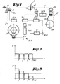
- Figure 1 is a schematic representation of the most important components involved in the weaving process, ie. the warp beam 1, the warp threads 2, the warp tensioner 3, the shed 4, the frames 5, the reed 6, the cloth or textile 7, the cloth or textile take-up 8 with the breast beam 8A and the cloth beam 8B, and the weaving machine main drive motor 9.
- the warp let-off is controlled by a control unit 10, using the tension in the warp threads and/or the speed of the weaving machine 2 to adjust the amount of warp let-off.
- the warp tension can be determined in the normal way, for example by detecting the displacement of the warp tensioner 3 as it presses in towards the elastic restraint 11, while the weaving machine speed can be measured directly on the main drive motor 9.
- control unit 10 One or both of the detected signals representative of the warp tension are then fed via the appropriate regulator (12A or 12B respectively) to eg. control unit 10.
- Control unit 10 then supplies a signal to controller 13A, which controls warp let-off motor 14A. This signal is a function of the detected warp tension and machine speed.
- Motor 14A is coupled to warp beam 1 by an appropriate transmission 15A.
- a signal from control unit 10 is supplied to controller 13B of a cloth take-up motor 14B; however in this case the signal should preferably be a function of the detected machine speed only.
- Controllers 13A and 13B should preferably be frequency controllers.
- 16A and 16B can be a tachogenerator; or it can be a current meter which measures the current supplied to the motor, as this is representative of the motor speed.
- This characteristic can be used in the method of the invention, for example by means of the following configurations:
- the effects of variations in warp tension and machine speed due to the weave pattern are suppressed by taking the signal representing the warp tension or machine speed and filtering out all disturbance components with a frequency equal to the frequency of the variations caused by the weave pattern or a multiple thereof.
- This can be done by means of suitable regulators 12A and 12B.
- the resulting filtered signal is then passed in the conventional manner to controllers 13A and 13B of motors 14A and 14B.
- Controllers 13A and 13B can of course be of any type, for instance frequency controllers if the motors are frequency-regulated.
- the process just described is illustrated by the frequency characteristic shown in fig. 2.
- the filtered signal is then sent to control unit 10, in order to command frequency controllers 13A and 13B of motors 14A and 14B.
- the lower frequencies are amplified more than the higher frequencies, while the highest frequencies are attenuated so as to eliminate them completely, as shown in fig. 3. Since the lower frequencies play a greater role in determining the appearance of the cloth, this variant has a favorable effect on the end result.
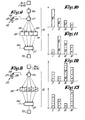
- the operating process used to eliminate the warp tension variations caused by the weave pattern is illustrated in fig. 5.
- the tension meter or detector 16A continuously measures the tension in the warp threads 2, and passes this value to integrators 17 - 20, which are switched on and off by trigger 22 and control unit 21.
- Integrator 17 is activated at time T1 and integrates the measured warp tension over a particular period A.
- integrators 18, 19 and 20 are activated at times T2, T3 and T4 and integrate the warp tension over periods B, C and D respectively.
- the essential point here is that the duration of periods A, B, C and D is equal to the period T necessary to form one complete weave pattern, or a multiple thereof, while times Tl to T4 are chosen so that they overlap each of the periods A to D.
- the integration results generated by integrators 17 to 20 at the end of periods A to D are representative of the tension in the warp threads 2, but without being influenced by the variations in warp tension caused by the weave pattern. Due to the fact that the periods A to D overlap, it is not necessary to wait until a period T has elapsed before being able to supply a measurement result to control unit 21 of warp let-off drive 25.
- Trigger 22 and control unit 21 should preferably control integrators 17 to 20 in such a way that time Tl coincides with the beginning of a new weave pattern, while the subsequent times at which integrators 18 to 20 are activated are evenly distributed over the time interval T. Times Tl, T2 etc. should also preferably be chosen so that they coincide with successive starts of the weaving cycles. Since the integrations are carried out over a period equal to the period necessary for forming one complete weave pattern, the integrators can be activated at any desired angular position of the weaving machine.
- fig. 7 Since the weave pattern is known beforehand, the variation of tension with time can be calculated for particular time intervals, eg. in this case for the time intervals Tl to T2, T2 to T3 etc. The four values obtained are entered in comparators 28 to 31. The tension in the warp threads 2 is then integrated separately for each of the periods E to H and then E' to H' etc. shown in fig. 7. Then, according to the control diagram shown in fig. 6:
- the method of the invention also fits the process just described.
- the duration of the integration intervals E., F, G and H should correspond to the duration of successive weaving cycles.
- the configuration shown in fig. 8 also uses an integrator 26. After this integrator 26 there is a series 32 of adders I, II, III and IV, which one after the other send signals to control unit 21.
- Integrator 26 operates in turn over the partial periods I, J, K, L, I', J', K' and L' which form identical sequences 33, each with a total duration equal to the period T necessary to form one or more complete weave patterns.
- the integration result W over the partial period I is supplied to the memory of adder I;
- the integration result X over the partial period J is supplied to the memories of adders I and II;
- the corresponding result Y is supplied to I, II and III;
- the result Z is supplied to the memories of all four adders.
- the memory of adder I contains the total value W + X + Y +Z, which corresponds to the integration of the warp tension over the immediately preceding period with duration equal to time T.
- This total value is therefore representative of the variations in tension of the warp threads 2, but without taking into account the variations in tension due to the weave pattern.
- the total value W + X + Y + Z is equal to the integration result obtained over the integration period A in fig. 55.
- the total value thus obtained is sent by adder I to control unit 21 in order to regulate the warp drive motor, and the adder is then reset at zero.
- the value W' is added to the memory of all the adders.
- the memory of adder II contains the total value X + Y + Z + W', which is similarly passed to control unit 21:
- the operating process can then continue in the same way, with the total value in each memory being sent to control unit 21 as soon as it is equivalent to an integration of the warp tension for the period just past with duration equal to the duration of the abovementioned series 33, ie. period T.
- adder II is then supplied to control unit 21.
- adder I is reset to zero.
- the value X is taken from integrator 26 and placed in the memory of adder I; also it is multiplied by 2.0 and added to the memory of adder II, multiplied by 1.5 and added to the memory of adder III, and finally it is multiplied by 1.0 and added to the memory of adder IV (fig. 11).
- the value stored in adder II is sent to control unit 21 in order to control the warp let-off drive.
- adder II is reset at zero.
- the signals 34 can also be sent to control unit 21, for example after a machine stop, in order to instruct control unit 21 to follow the special start procedure.
- this time described with reference to measurement of the machine speed the time necessary to form one complete weave pattern is measured, for example using a wheel with 36 teeth which rotates at the same speed as the main drive motor.
- a weave pattern for which four machine cycles are necessary will correspond to 144 teeth.
- the teeth are detected by a fixed detector. Each time one of the teeth passes the detector, a clock is started; it is reset at zero when 144 teeth have passed, thus measuring the time necessary for one complete weave pattern.
- This value is representative of the machine speed, but independent of the weave pattern, as required for the invention.
- This method yields 36 representative values for the machine speed. Obviously a special startup procedure will have to be used when starting up the weaving machine.
- the method of the invention can also be applied by taking the average of the abovementioned intervals, in order to obtain representative values for these intervals.
- the machine can then be controlled in the normal way, by means of control unit 10.
- the machine should be controlled as follows: the motor speed is governed at a value K multiplied by the filtered signal, where the value of K varies according to the weaving process. Where there are large variations in tension, the value of K can be automatically increased or reduced in order to achieve faster correction.
- the value of K can also be a function of the beam diameter or the interweaving, or can change suddenly when there is a transition from one type of textile to another, for example a change to a different weave with a corresponding change in the period necessary to form the weave pattern.
- the invention is not limited to the examples described above and the configurations shown in the figures; on the contrary, the method for controlling the warp let-off on weaving machines can be applied according to many variants.
Landscapes
- Engineering & Computer Science (AREA)
- Textile Engineering (AREA)
- Looms (AREA)
Applications Claiming Priority (2)
| Application Number | Priority Date | Filing Date | Title |
|---|---|---|---|
| BE2061037 | 1986-08-22 | ||
| BE2/61037A BE905314A (nl) | 1986-08-22 | 1986-08-22 | Werkwijze voor de sturing van de kettingaflaat en de doekopwikkeling bij weefmachines. |
Publications (2)
| Publication Number | Publication Date |
|---|---|
| EP0257707A2 true EP0257707A2 (fr) | 1988-03-02 |
| EP0257707A3 EP0257707A3 (fr) | 1991-02-27 |
Family
ID=3865820
Family Applications (1)
| Application Number | Title | Priority Date | Filing Date |
|---|---|---|---|
| EP19870201562 Withdrawn EP0257707A3 (fr) | 1986-08-22 | 1987-08-18 | Méthode pour contrôler le déroulement de la chaíne et l'enroulement du tissu dans les métiers à tisser |
Country Status (3)
| Country | Link |
|---|---|
| US (1) | US4817677A (fr) |
| EP (1) | EP0257707A3 (fr) |
| BE (1) | BE905314A (fr) |
Cited By (2)
| Publication number | Priority date | Publication date | Assignee | Title |
|---|---|---|---|---|
| EP0350980A1 (fr) * | 1988-07-12 | 1990-01-17 | Picanol N.V. | Dispositif pour régler la tension de la chaîne dans les métiers à tisser |
| DE4325038A1 (de) * | 1992-08-18 | 1994-02-24 | Regatron Ag Steinach | Regeleinrichtung für den Vorschub von Wickelgut einer Webmaschine |
Families Citing this family (11)
| Publication number | Priority date | Publication date | Assignee | Title |
|---|---|---|---|---|
| JPH01250439A (ja) * | 1988-03-29 | 1989-10-05 | Nissan Motor Co Ltd | 織機の巻き取り送り出し方法 |
| JP2894709B2 (ja) * | 1988-12-28 | 1999-05-24 | 株式会社豊田中央研究所 | 経糸速度制御装置 |
| BE1002819A3 (nl) * | 1989-02-06 | 1991-06-18 | Picanol Nv | Werkwijze voor het weven van een weefsel met een weefselpatroon, en weefmachines die deze werkwijze toepassen. |
| SE470314B (sv) * | 1992-06-10 | 1994-01-17 | Aelmhults Bruk Ab | Kontrollanordning för varptrådsspänning innefattande sträckbromssystem med mot varandra med varptrådar mellanliggande pressade bommar |
| IT1255566B (it) * | 1992-10-23 | 1995-11-09 | Luciano Corain | Dispositivo perfezionato per variare automaticamente la posizione del vertice della bocca di ordito in un telaio tessile. |
| JP3318394B2 (ja) * | 1993-06-02 | 2002-08-26 | 株式会社石川製作所 | 空気噴射式織機における運転再開方法 |
| DE59605592D1 (de) * | 1996-02-05 | 2000-08-17 | Sulzer Textil Ag Rueti | Verfahren und Vorrichtung zum Messen der Spannung der Webkette in einer Webmaschine |
| US20020195160A1 (en) * | 2001-06-26 | 2002-12-26 | Sulzer Textil Ag | Method and apparatus for the regulation of the warp let-off a weaving machine |
| JP5095316B2 (ja) * | 2007-09-05 | 2012-12-12 | 東芝機械株式会社 | 織機及び織機の駆動装置。 |
| KR100976929B1 (ko) * | 2008-04-16 | 2010-08-18 | 소진수 | 실공급방법, 경사공급방법, 실공급장치 및 직조방법 |
| JP5909042B2 (ja) * | 2011-01-21 | 2016-04-26 | 津田駒工業株式会社 | 織機における経糸送り方法および装置 |
Family Cites Families (8)
| Publication number | Priority date | Publication date | Assignee | Title |
|---|---|---|---|---|
| BE768521R (nl) * | 1971-02-26 | 1971-11-03 | Weefautomaten Picanol N V Meti | Kettingafwinder voor |
| CH556416A (de) * | 1972-09-29 | 1974-11-29 | Sulzer Ag | Kettablassvorrichtung. |
| DE2939607C2 (de) * | 1979-09-29 | 1983-10-27 | Maschinenfabrik Stromag Gmbh, 4750 Unna | Regeleinrichtung für den Antrieb eines Kettablasses einer Webmaschine |
| DE3111113C2 (de) * | 1981-03-20 | 1986-01-23 | Karl Mayer Textil-Maschinen-Fabrik Gmbh, 6053 Obertshausen | Regelvorrichtung für den Motor einer das Gewirk beeinflussenden Wickelvorrichtung, wie Teilkettbaum, bei einer Kettenwirkmaschine |
| CH661754A5 (de) * | 1983-10-04 | 1987-08-14 | Saurer Ag Adolph | Regeleinrichtung fuer den drehantrieb einer abwickelvorrichtung. |
| JPS60155757A (ja) * | 1984-01-20 | 1985-08-15 | 津田駒工業株式会社 | 織機の電動送り出し・巻取制御方法およびその装置 |
| JPS60181349A (ja) * | 1984-02-24 | 1985-09-17 | 津田駒工業株式会社 | 織機の巻取り制御装置 |
| DE3520244A1 (de) * | 1984-08-24 | 1986-03-06 | Aktiengesellschaft Adolph Saurer, Arbon | Warenabzugseinrichtung an einer webmaschine |
-
1986
- 1986-08-22 BE BE2/61037A patent/BE905314A/nl not_active IP Right Cessation
-
1987
- 1987-08-18 EP EP19870201562 patent/EP0257707A3/fr not_active Withdrawn
- 1987-08-21 US US07/087,824 patent/US4817677A/en not_active Expired - Lifetime
Cited By (3)
| Publication number | Priority date | Publication date | Assignee | Title |
|---|---|---|---|---|
| EP0350980A1 (fr) * | 1988-07-12 | 1990-01-17 | Picanol N.V. | Dispositif pour régler la tension de la chaîne dans les métiers à tisser |
| BE1002312A3 (nl) * | 1988-07-12 | 1990-11-27 | Picanol Nv | Inrichting voor het instellen van de kettingspanning bij een weefmachine. |
| DE4325038A1 (de) * | 1992-08-18 | 1994-02-24 | Regatron Ag Steinach | Regeleinrichtung für den Vorschub von Wickelgut einer Webmaschine |
Also Published As
| Publication number | Publication date |
|---|---|
| EP0257707A3 (fr) | 1991-02-27 |
| US4817677A (en) | 1989-04-04 |
| BE905314A (nl) | 1987-02-23 |
Similar Documents
| Publication | Publication Date | Title |
|---|---|---|
| US4817677A (en) | Method for controlling the warp let-off and cloth take-up on weaving machines | |
| EP0164773B1 (fr) | Commande réglable du fil de trame dans un métier à tisser | |
| US4049211A (en) | Winding apparatus for textile threads | |
| DE69415131T2 (de) | Verfahren zum Regeln der Drehzahl eines Waschmaschinenmotors | |
| US4605044A (en) | Takeup motion control device for looms | |
| JPH0694614B2 (ja) | 織機の電動送り出し方法およびその装置 | |
| US4529012A (en) | Apparatus for controlling motor-driven let-off motion for looms | |
| EP0495511B1 (fr) | Machine de découpe à fil par électroérosion | |
| US4593236A (en) | Regulation device for the rotary drive of a supply roll device, especially a warp beam of a weaving machine | |
| EP0496838B1 (fr) | Procede et appareil de commande electronique pour metier a tissu eponge | |
| US4452402A (en) | Electric control for yarn feeding devices | |
| US5568826A (en) | Pile warp dispensing in advance of beat-up in a terry loom | |
| US5699837A (en) | Combined pile feeder control system and pile warp let-off motion for pile weaving machine | |
| US6068028A (en) | Yarn scanning process and yarn unwinding sensor | |
| JPH0735623B2 (ja) | よこ糸密度制御方法およびその装置 | |
| JPH03503298A (ja) | 糸巻き貯蔵供給装置及びその制御方法 | |
| EP1331295A2 (fr) | Procédé et dispositif pour supprimer des barrures en trame pour un métier à tisser | |
| US20020195160A1 (en) | Method and apparatus for the regulation of the warp let-off a weaving machine | |
| CZ278076B6 (en) | Weft stop motion for checking and detecting weft break | |
| JPS633054B2 (fr) | ||
| DE4205816A1 (de) | Programmgesteuerte waschmaschine | |
| RU2018480C1 (ru) | Способ управления питателем-накопителем пряжи для ткацкого станка и устройство для его осуществления | |
| CN106245220A (zh) | 一种多梳经编机花梳送经控制实现方法 | |
| US4749460A (en) | Plating current automatic compensating apparatus | |
| JPH0791733B2 (ja) | 織機における経糸送り出し制御方法 |
Legal Events
| Date | Code | Title | Description |
|---|---|---|---|
| PUAI | Public reference made under article 153(3) epc to a published international application that has entered the european phase |
Free format text: ORIGINAL CODE: 0009012 |
|
| AK | Designated contracting states |
Kind code of ref document: A2 Designated state(s): CH DE FR IT LI NL |
|
| PUAL | Search report despatched |
Free format text: ORIGINAL CODE: 0009013 |
|
| AK | Designated contracting states |
Kind code of ref document: A3 Designated state(s): CH DE FR IT LI NL |
|
| 17P | Request for examination filed |
Effective date: 19910308 |
|
| 17Q | First examination report despatched |
Effective date: 19920610 |
|
| STAA | Information on the status of an ep patent application or granted ep patent |
Free format text: STATUS: THE APPLICATION IS DEEMED TO BE WITHDRAWN |
|
| 18D | Application deemed to be withdrawn |
Effective date: 19930706 |
|
| RIN1 | Information on inventor provided before grant (corrected) |
Inventor name: DECONINCK, FILIP Inventor name: CAPPELAERE, JOHAN Inventor name: VANDEWEGHE, MICHEL |