EP0257707A2 - A method for controlling the warp let-off and cloth take-up on weaving machines - Google Patents
A method for controlling the warp let-off and cloth take-up on weaving machines Download PDFInfo
- Publication number
- EP0257707A2 EP0257707A2 EP87201562A EP87201562A EP0257707A2 EP 0257707 A2 EP0257707 A2 EP 0257707A2 EP 87201562 A EP87201562 A EP 87201562A EP 87201562 A EP87201562 A EP 87201562A EP 0257707 A2 EP0257707 A2 EP 0257707A2
- Authority
- EP
- European Patent Office
- Prior art keywords
- warp
- characteristic
- period
- weave pattern
- detected signal
- Prior art date
- Legal status (The legal status is an assumption and is not a legal conclusion. Google has not performed a legal analysis and makes no representation as to the accuracy of the status listed.)
- Withdrawn
Links
Images

Classifications
-
- D—TEXTILES; PAPER
- D03—WEAVING
- D03D—WOVEN FABRICS; METHODS OF WEAVING; LOOMS
- D03D49/00—Details or constructional features not specially adapted for looms of a particular type
- D03D49/04—Control of the tension in warp or cloth
-
- D—TEXTILES; PAPER
- D03—WEAVING
- D03D—WOVEN FABRICS; METHODS OF WEAVING; LOOMS
- D03D49/00—Details or constructional features not specially adapted for looms of a particular type
- D03D49/04—Control of the tension in warp or cloth
- D03D49/06—Warp let-off mechanisms
Definitions
- This invention concerns a method for controlling the warp le.t-off and cloth take-up motions on weaving machines, and in particular a method of processing the associated control signals so that they are not affected by the weaving pattern.
- textile quality depends to a large extent on the tension and speed of motion of the warp threads during weaving.
- the speed of motion of the warp threads depends on the speed of motion of the cloth, which in turn depends on the operating speed of the weaving machine.
- the difference between the speed of motion of the warp threads and the cloth respectively is dependent on the interweaving. Normally, all measures are of course taken to control the warp thread speed so that the tension in the warp threads is kept as constant as possible.
- the instantaneous tension is measured and used to control the warp let-off.
- the instantaneous speed of the weaving machine drive motor is measured and used to control the warp let-off.
- this method of operation has the disadvantage that the control system reacts to all disturbance signals, even although compensation is not necessary for disturbance signals of very short duration, since these tend to be self-compensating. If a compensation function is nevertheless generated, there is a risk of overcompensation, with all the attendant disadvantages for the quality of the textile.
- the main disturbance signals for which the control system does not need to provide compensation are the periodic variations in warp tension and machine speed caused by the weaving pattern.
- the object of this invention is to provide a method for systematically avoid these disadvantages.
- the method used in this invention mainly consists of: detecting the variation with time of one or more of the parameters which are a function of the warp tension and/or warp speed; taking the signal thus obtained and removing those components which are due to variations in the weaving pattern; using the resulting clean signal to control the warp let-off and/or cloth take-up.
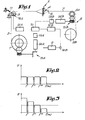
- Figure 1 is a schematic representation of the most important components involved in the weaving process, ie. the warp beam 1, the warp threads 2, the warp tensioner 3, the shed 4, the frames 5, the reed 6, the cloth or textile 7, the cloth or textile take-up 8 with the breast beam 8A and the cloth beam 8B, and the weaving machine main drive motor 9.
- the warp let-off is controlled by a control unit 10, using the tension in the warp threads and/or the speed of the weaving machine 2 to adjust the amount of warp let-off.
- the warp tension can be determined in the normal way, for example by detecting the displacement of the warp tensioner 3 as it presses in towards the elastic restraint 11, while the weaving machine speed can be measured directly on the main drive motor 9.
- control unit 10 One or both of the detected signals representative of the warp tension are then fed via the appropriate regulator (12A or 12B respectively) to eg. control unit 10.
- Control unit 10 then supplies a signal to controller 13A, which controls warp let-off motor 14A. This signal is a function of the detected warp tension and machine speed.
- Motor 14A is coupled to warp beam 1 by an appropriate transmission 15A.
- a signal from control unit 10 is supplied to controller 13B of a cloth take-up motor 14B; however in this case the signal should preferably be a function of the detected machine speed only.
- Controllers 13A and 13B should preferably be frequency controllers.
- 16A and 16B can be a tachogenerator; or it can be a current meter which measures the current supplied to the motor, as this is representative of the motor speed.
- This characteristic can be used in the method of the invention, for example by means of the following configurations:
- the effects of variations in warp tension and machine speed due to the weave pattern are suppressed by taking the signal representing the warp tension or machine speed and filtering out all disturbance components with a frequency equal to the frequency of the variations caused by the weave pattern or a multiple thereof.
- This can be done by means of suitable regulators 12A and 12B.
- the resulting filtered signal is then passed in the conventional manner to controllers 13A and 13B of motors 14A and 14B.
- Controllers 13A and 13B can of course be of any type, for instance frequency controllers if the motors are frequency-regulated.
- the process just described is illustrated by the frequency characteristic shown in fig. 2.
- the filtered signal is then sent to control unit 10, in order to command frequency controllers 13A and 13B of motors 14A and 14B.
- the lower frequencies are amplified more than the higher frequencies, while the highest frequencies are attenuated so as to eliminate them completely, as shown in fig. 3. Since the lower frequencies play a greater role in determining the appearance of the cloth, this variant has a favorable effect on the end result.
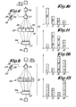
- the operating process used to eliminate the warp tension variations caused by the weave pattern is illustrated in fig. 5.
- the tension meter or detector 16A continuously measures the tension in the warp threads 2, and passes this value to integrators 17 - 20, which are switched on and off by trigger 22 and control unit 21.
- Integrator 17 is activated at time T1 and integrates the measured warp tension over a particular period A.
- integrators 18, 19 and 20 are activated at times T2, T3 and T4 and integrate the warp tension over periods B, C and D respectively.
- the essential point here is that the duration of periods A, B, C and D is equal to the period T necessary to form one complete weave pattern, or a multiple thereof, while times Tl to T4 are chosen so that they overlap each of the periods A to D.
- the integration results generated by integrators 17 to 20 at the end of periods A to D are representative of the tension in the warp threads 2, but without being influenced by the variations in warp tension caused by the weave pattern. Due to the fact that the periods A to D overlap, it is not necessary to wait until a period T has elapsed before being able to supply a measurement result to control unit 21 of warp let-off drive 25.
- Trigger 22 and control unit 21 should preferably control integrators 17 to 20 in such a way that time Tl coincides with the beginning of a new weave pattern, while the subsequent times at which integrators 18 to 20 are activated are evenly distributed over the time interval T. Times Tl, T2 etc. should also preferably be chosen so that they coincide with successive starts of the weaving cycles. Since the integrations are carried out over a period equal to the period necessary for forming one complete weave pattern, the integrators can be activated at any desired angular position of the weaving machine.
- fig. 7 Since the weave pattern is known beforehand, the variation of tension with time can be calculated for particular time intervals, eg. in this case for the time intervals Tl to T2, T2 to T3 etc. The four values obtained are entered in comparators 28 to 31. The tension in the warp threads 2 is then integrated separately for each of the periods E to H and then E' to H' etc. shown in fig. 7. Then, according to the control diagram shown in fig. 6:
- the method of the invention also fits the process just described.
- the duration of the integration intervals E., F, G and H should correspond to the duration of successive weaving cycles.
- the configuration shown in fig. 8 also uses an integrator 26. After this integrator 26 there is a series 32 of adders I, II, III and IV, which one after the other send signals to control unit 21.
- Integrator 26 operates in turn over the partial periods I, J, K, L, I', J', K' and L' which form identical sequences 33, each with a total duration equal to the period T necessary to form one or more complete weave patterns.
- the integration result W over the partial period I is supplied to the memory of adder I;
- the integration result X over the partial period J is supplied to the memories of adders I and II;
- the corresponding result Y is supplied to I, II and III;
- the result Z is supplied to the memories of all four adders.
- the memory of adder I contains the total value W + X + Y +Z, which corresponds to the integration of the warp tension over the immediately preceding period with duration equal to time T.
- This total value is therefore representative of the variations in tension of the warp threads 2, but without taking into account the variations in tension due to the weave pattern.
- the total value W + X + Y + Z is equal to the integration result obtained over the integration period A in fig. 55.
- the total value thus obtained is sent by adder I to control unit 21 in order to regulate the warp drive motor, and the adder is then reset at zero.
- the value W' is added to the memory of all the adders.
- the memory of adder II contains the total value X + Y + Z + W', which is similarly passed to control unit 21:
- the operating process can then continue in the same way, with the total value in each memory being sent to control unit 21 as soon as it is equivalent to an integration of the warp tension for the period just past with duration equal to the duration of the abovementioned series 33, ie. period T.
- adder II is then supplied to control unit 21.
- adder I is reset to zero.
- the value X is taken from integrator 26 and placed in the memory of adder I; also it is multiplied by 2.0 and added to the memory of adder II, multiplied by 1.5 and added to the memory of adder III, and finally it is multiplied by 1.0 and added to the memory of adder IV (fig. 11).
- the value stored in adder II is sent to control unit 21 in order to control the warp let-off drive.
- adder II is reset at zero.
- the signals 34 can also be sent to control unit 21, for example after a machine stop, in order to instruct control unit 21 to follow the special start procedure.
- this time described with reference to measurement of the machine speed the time necessary to form one complete weave pattern is measured, for example using a wheel with 36 teeth which rotates at the same speed as the main drive motor.
- a weave pattern for which four machine cycles are necessary will correspond to 144 teeth.
- the teeth are detected by a fixed detector. Each time one of the teeth passes the detector, a clock is started; it is reset at zero when 144 teeth have passed, thus measuring the time necessary for one complete weave pattern.
- This value is representative of the machine speed, but independent of the weave pattern, as required for the invention.
- This method yields 36 representative values for the machine speed. Obviously a special startup procedure will have to be used when starting up the weaving machine.
- the method of the invention can also be applied by taking the average of the abovementioned intervals, in order to obtain representative values for these intervals.
- the machine can then be controlled in the normal way, by means of control unit 10.
- the machine should be controlled as follows: the motor speed is governed at a value K multiplied by the filtered signal, where the value of K varies according to the weaving process. Where there are large variations in tension, the value of K can be automatically increased or reduced in order to achieve faster correction.
- the value of K can also be a function of the beam diameter or the interweaving, or can change suddenly when there is a transition from one type of textile to another, for example a change to a different weave with a corresponding change in the period necessary to form the weave pattern.
- the invention is not limited to the examples described above and the configurations shown in the figures; on the contrary, the method for controlling the warp let-off on weaving machines can be applied according to many variants.
Landscapes
- Engineering & Computer Science (AREA)
- Textile Engineering (AREA)
- Looms (AREA)
Abstract
Description
- This invention concerns a method for controlling the warp le.t-off and cloth take-up motions on weaving machines, and in particular a method of processing the associated control signals so that they are not affected by the weaving pattern.
- As is well known, textile quality depends to a large extent on the tension and speed of motion of the warp threads during weaving. The speed of motion of the warp threads depends on the speed of motion of the cloth, which in turn depends on the operating speed of the weaving machine. As explained in BE 768.521 the difference between the speed of motion of the warp threads and the cloth respectively is dependent on the interweaving. Normally, all measures are of course taken to control the warp thread speed so that the tension in the warp threads is kept as constant as possible. In BE 768 521 the instantaneous tension is measured and used to control the warp let-off. Likewise in BE 768.521 the instantaneous speed of the weaving machine drive motor is measured and used to control the warp let-off.
- Also in BE 768.521 the speed of the cloth take-up is directly determined by the speed of the main drive motor.
- However, this method of operation has the disadvantage that the control system reacts to all disturbance signals, even although compensation is not necessary for disturbance signals of very short duration, since these tend to be self-compensating. If a compensation function is nevertheless generated, there is a risk of overcompensation, with all the attendant disadvantages for the quality of the textile. The main disturbance signals for which the control system does not need to provide compensation are the periodic variations in warp tension and machine speed caused by the weaving pattern.
- The object of this invention is to provide a method for systematically avoid these disadvantages. The method used in this invention mainly consists of: detecting the variation with time of one or more of the parameters which are a function of the warp tension and/or warp speed; taking the signal thus obtained and removing those components which are due to variations in the weaving pattern; using the resulting clean signal to control the warp let-off and/or cloth take-up.
- Since the variations caused by the weaving pattern are always periodic, it is better not to feed them through to the warp drive, warp let-off or cloth take-up if the abovementioned disadvantages are to be avoided.
- There are various processes by which the method described in the invention can be applied, either by filtering out a number of disturbance signals or by processing the signal in one or more stages in order to provide a value which is representative of the signal over a duration equal to the period necessary for the formation of a complete weave pattern or a multiple thereof. Suitable processes include integration or determining the average of the signal over the relevant period.
- In order to explain the characteristics of the invention, the following preferred embodiments are described, by way of example only and without being limitative in any way, where:
- - fig. 1 is a schematic representation of the weaving process;
- - figs. 2 and 3 represent the filter functions obtained in one configuration of the invention;
- - fig. 4 is the control diagram for another configuration;
- - fig. 5 represents the integration periods used for the configuration in fig. 4;
- - fig. 6 is the control diagram for yet another configuration;
- - fig. 7 represents the method of integration over time for the control diagram shown in fig. 6;
- - fig. 8 shows yet another possible control diagram;
- - fig. 9 shows the time sequence of the integration periods over which the integrations for the control diagram in fig. 8 are carried out.
- - figs. 10 to 13 illustrate the startup sequence after a machine stop, for the control diagram shown in fig. 8.
- Figure 1 is a schematic representation of the most important components involved in the weaving process, ie. the warp beam 1, the
warp threads 2, thewarp tensioner 3, the shed 4, theframes 5, thereed 6, the cloth or textile 7, the cloth or textile take-up 8 with thebreast beam 8A and thecloth beam 8B, and the weaving machinemain drive motor 9. The warp let-off is controlled by acontrol unit 10, using the tension in the warp threads and/or the speed of theweaving machine 2 to adjust the amount of warp let-off. - The warp tension can be determined in the normal way, for example by detecting the displacement of the
warp tensioner 3 as it presses in towards theelastic restraint 11, while the weaving machine speed can be measured directly on themain drive motor 9. - One or both of the detected signals representative of the warp tension are then fed via the appropriate regulator (12A or 12B respectively) to eg.
control unit 10.Control unit 10 then supplies a signal to controller 13A, which controls warp let-offmotor 14A. This signal is a function of the detected warp tension and machine speed. Motor 14A is coupled to warp beam 1 by anappropriate transmission 15A. - In a similar way, a signal from
control unit 10 is supplied tocontroller 13B of a cloth take-up motor 14B; however in this case the signal should preferably be a function of the detected machine speed only. -
Controllers - In fig. 1 the warp tension and machine speed detectors are indicated in a general manner only, by 16A and 16B respectively. For example, 16B can be a tachogenerator; or it can be a current meter which measures the current supplied to the motor, as this is representative of the motor speed.
- In the methods previously used, all types of disturbance signal, including periodic disturbances, are passed to
regulators motors - In this invention however, periodic disturbances which are liable to cause overcompensation in warp let-off
motor 14A and/or cloth take-up motor 14B are ignored, in particular the disturbance signals due to the weaving pattern. Here it should be noted that since the warp extension caused by the upper frames differs from that caused by the lower frames, and similarly there is a difference in the warp extension caused by the front and rear frames, the period of these periodic disturbance signals corresponds to the time necessary to form a complete weave pattern. Similarly, due to the difference in motion of the frames, the power drawn frommain drive motor 9 also varies periodically according to the weave pattern, and so also does the machine speed. This characteristic can be used in the method of the invention, for example by means of the following configurations: In the first configuration using the method of the invention, the effects of variations in warp tension and machine speed due to the weave pattern are suppressed by taking the signal representing the warp tension or machine speed and filtering out all disturbance components with a frequency equal to the frequency of the variations caused by the weave pattern or a multiple thereof. This can be done by means ofsuitable regulators controllers motors Controllers - The process just described is illustrated by the frequency characteristic shown in fig. 2. The frequency f of the warp tension variations due to the weave pattern -can be calculated beforehand from the weave pattern and the known machine speed, since f is equal to the quotient of the frequency of the machine speed f(m) and the number of machine cycles necessary to form one complete weave pattern. In the example shown in fig. 2, one complete weave pattern is formed in four machine cycles, therefore f is 1/4 of f(m). Accordingly,
regulators - The filtered signal is then sent to control
unit 10, in order to commandfrequency controllers motors - In a variant configuration, in addition to the filtering just described all signals with frequency greater than the machine frequency f(m) can be eliminated, eg. using a low pass filter as shown in fig. 2.
- In another variant, in addition to being filtered the lower frequencies are amplified more than the higher frequencies, while the highest frequencies are attenuated so as to eliminate them completely, as shown in fig. 3. Since the lower frequencies play a greater role in determining the appearance of the cloth, this variant has a favorable effect on the end result.
- In the variants described below, instead of a filter one or more integrators are used to eliminate the variations in tension due to the weave pattern. Note that although the following variants are only described for the warp'tension signal (
detector 16A), they are also applicable to the machine speed signal (detector 16B). 'The control diagram for one possible configuration is shown in fig. 4. This configuration uses a tension meter or'detector 16A, a number of integrators (17 - 20), acontrol unit 21, atrigger 22 consisting of eg. acam 23 mounted on a shaft 24 (ganged to the machine speed) and aproximity switch 25, andcontrol unit 10.Integrators 17 to 20 andcontrol unit 21 correspond toregulator 12A used in the previous configurations. - The operating process used to eliminate the warp tension variations caused by the weave pattern is illustrated in fig. 5. The tension meter or
detector 16A continuously measures the tension in thewarp threads 2, and passes this value to integrators 17 - 20, which are switched on and off bytrigger 22 andcontrol unit 21.Integrator 17 is activated at time T1 and integrates the measured warp tension over a particular period A. Similarly,integrators - Since the duration of periods A, B, C and D is equal to or a multiple of the time T necessary to form one complete weave pattern, the integration results generated by
integrators 17 to 20 at the end of periods A to D, ie. at times T1' to T4' respectively, are representative of the tension in thewarp threads 2, but without being influenced by the variations in warp tension caused by the weave pattern. Due to the fact that the periods A to D overlap, it is not necessary to wait until a period T has elapsed before being able to supply a measurement result to controlunit 21 of warp let-off drive 25. - Each time one of the
integrators 17 to 20 has carried out an integration over one of the corresponding periods A to D, the result is passed to controlunit 21, the integrator is reset to zero and a new integration begins over the next period A's B', C' or D'. -
Trigger 22 andcontrol unit 21 should preferably controlintegrators 17 to 20 in such a way that time Tl coincides with the beginning of a new weave pattern, while the subsequent times at whichintegrators 18 to 20 are activated are evenly distributed over the time interval T. Times Tl, T2 etc. should also preferably be chosen so that they coincide with successive starts of the weaving cycles. Since the integrations are carried out over a period equal to the period necessary for forming one complete weave pattern, the integrators can be activated at any desired angular position of the weaving machine. - As can be seen from the control diagram shown in fig. 6, it is also possible to use just one
integrator 26. Pulses fromtrigger 22 are used to controldistributor 27, which connectsintegrator 26 to a number of comparators in turn, in this case the fourcomparators 28 to 31. These comparators commandcontrol unit 21.Trigger 22 ensures that the integrator is reset at zero at set times, and thatdistributor 27 supplies the integration results tocomparators 28 to 31 successively. - The operating process for this configuration is illustrated by fig. 7. Since the weave pattern is known beforehand, the variation of tension with time can be calculated for particular time intervals, eg. in this case for the time intervals Tl to T2, T2 to T3 etc. The four values obtained are entered in
comparators 28 to 31. The tension in thewarp threads 2 is then integrated separately for each of the periods E to H and then E' to H' etc. shown in fig. 7. Then, according to the control diagram shown in fig. 6: - - at time T2 the integration result for period E is compared in
comparator 28 with the precalculated warp tension for time interval E; - - at time T3 the integration result for period F is compared in
comparator 29 with the precalculated warp tension for time interval F; - - etc.
- Clearly, the method of the invention also fits the process just described. The duration of the integration intervals E., F, G and H should correspond to the duration of successive weaving cycles.
- The configuration shown in fig. 8 also uses an
integrator 26. After thisintegrator 26 there is aseries 32 of adders I, II, III and IV, which one after the other send signals to controlunit 21. - The operating process for this configuration is shown in fig. 9.
Integrator 26 operates in turn over the partial periods I, J, K, L, I', J', K' and L' which formidentical sequences 33, each with a total duration equal to the period T necessary to form one or more complete weave patterns. At time T2 the integration result W over the partial period I is supplied to the memory of adder I; at time T3 the integration result X over the partial period J is supplied to the memories of adders I and II; at time T4 the corresponding result Y is supplied to I, II and III; and at time T5 the result Z is supplied to the memories of all four adders. - At that moment, the memory of adder I contains the total value W + X + Y +Z, which corresponds to the integration of the warp tension over the immediately preceding period with duration equal to time T. This total value is therefore representative of the variations in tension of the
warp threads 2, but without taking into account the variations in tension due to the weave pattern. Here it should be noted that the total value W + X + Y + Z is equal to the integration result obtained over the integration period A in fig. 55. - The total value thus obtained is sent by adder I to control
unit 21 in order to regulate the warp drive motor, and the adder is then reset at zero. At time T2' the value W' is added to the memory of all the adders. At that moment the memory of adder II contains the total value X + Y + Z + W', which is similarly passed to control unit 21: The operating process can then continue in the same way, with the total value in each memory being sent to controlunit 21 as soon as it is equivalent to an integration of the warp tension for the period just past with duration equal to the duration of theabovementioned series 33, ie. period T. - In the configurations shown in figs. 6 and 8, it is necessary for a period T to elapse before control signals can be sent to control
unit 21. However, it is of course possible to generate intermediate values. One method of doing this for the configuration fig. 8 is shown schematically in figs. 10 to 13. Here, during the first partial period I control is carried out on the basis of values still present in memory from the previous measurement. As soon as value W arrives atintegrator 26, it is multiplied by 4.0 and added to the memory of adder I; also it is multiplied by 2.0 and added to the memory of adder II, multiplied by 1.5 and added to the memory of adder III, and finally multiplied by 1.0 and added to the memory of adder IV (fig. 10). The value 4W from adder I is then supplied to controlunit 21. During the second partial period J, adder I is reset to zero. At time T3 the value X is taken fromintegrator 26 and placed in the memory of adder I; also it is multiplied by 2.0 and added to the memory of adder II, multiplied by 1.5 and added to the memory of adder III, and finally it is multiplied by 1.0 and added to the memory of adder IV (fig. 11). At this point the value stored in adder II is sent to controlunit 21 in order to control the warp let-off drive. Shortly thereafter, at the latest during partial period K, adder II is reset at zero. - From this point on the normal operating process is followed once more; ie. at time T4 value Y from
integrator 26 is added to the memory contents of the four adders, as shown in fig. 12. The total content of adder III is sent to controlunit 21, and the adder is then reset at zero. At time T5 the value Z obtained by integration over partial period L is passed fromintegrator 26 to the four adders I to IV, and the sum present in the memory of adder IV is sent to controlunit 21. The same procedure is followed with value W', then in the following step with value X', and so on. - As shown in figs. 4, 6 and 8, the
signals 34 can also be sent to controlunit 21, for example after a machine stop, in order to instructcontrol unit 21 to follow the special start procedure. - In yet another configuration of the invention, this time described with reference to measurement of the machine speed, the time necessary to form one complete weave pattern is measured, for example using a wheel with 36 teeth which rotates at the same speed as the main drive motor. Thus a weave pattern for which four machine cycles are necessary will correspond to 144 teeth. The teeth are detected by a fixed detector. Each time one of the teeth passes the detector, a clock is started; it is reset at zero when 144 teeth have passed, thus measuring the time necessary for one complete weave pattern. This value is representative of the machine speed, but independent of the weave pattern, as required for the invention. This method yields 36 representative values for the machine speed. Obviously a special startup procedure will have to be used when starting up the weaving machine.
- Clearly, all the variants described above with reference to figs. 4 to 13 can also be applied to signals obtained by measuring the machine speed. Such signals may consist simply of the voltage supplied by the abovementioned tachogenerator.
- Although the configurations described so far all use integration, the method of the invention can also be applied by taking the average of the abovementioned intervals, in order to obtain representative values for these intervals.
- The machine can then be controlled in the normal way, by means of
control unit 10. Preferably, however, for the purposes of the invention the machine should be controlled as follows: the motor speed is governed at a value K multiplied by the filtered signal, where the value of K varies according to the weaving process. Where there are large variations in tension, the value of K can be automatically increased or reduced in order to achieve faster correction. The value of K can also be a function of the beam diameter or the interweaving, or can change suddenly when there is a transition from one type of textile to another, for example a change to a different weave with a corresponding change in the period necessary to form the weave pattern. - In such a case, ie. when there is a change in the weave, the period over which the required measurement is carried out must of course be modified automatically.
- Clearly, for both the warp tension and/or the motor speed, it is possible to measure either the variations or the absolute values.
- The invention is not limited to the examples described above and the configurations shown in the figures; on the contrary, the method for controlling the warp let-off on weaving machines can be applied according to many variants.
Claims (14)
Applications Claiming Priority (2)
| Application Number | Priority Date | Filing Date | Title |
|---|---|---|---|
| BE2/61037A BE905314A (en) | 1986-08-22 | 1986-08-22 | METHOD FOR CONTROLLING THE CHAIN LATE AND CLOTH WRAPPING IN WEAVING MACHINES. |
| BE2061037 | 1986-08-22 |
Publications (2)
| Publication Number | Publication Date |
|---|---|
| EP0257707A2 true EP0257707A2 (en) | 1988-03-02 |
| EP0257707A3 EP0257707A3 (en) | 1991-02-27 |
Family
ID=3865820
Family Applications (1)
| Application Number | Title | Priority Date | Filing Date |
|---|---|---|---|
| EP19870201562 Withdrawn EP0257707A3 (en) | 1986-08-22 | 1987-08-18 | A method for controlling the warp let-off and cloth take-up on weaving machines |
Country Status (3)
| Country | Link |
|---|---|
| US (1) | US4817677A (en) |
| EP (1) | EP0257707A3 (en) |
| BE (1) | BE905314A (en) |
Cited By (2)
| Publication number | Priority date | Publication date | Assignee | Title |
|---|---|---|---|---|
| EP0350980A1 (en) * | 1988-07-12 | 1990-01-17 | Picanol N.V. | Device for setting the warp tension on a weaving machine |
| DE4325038A1 (en) * | 1992-08-18 | 1994-02-24 | Regatron Ag Steinach | Loom warp let-off and cloth take-up motions - have electronic monitor and control for a faultless restart |
Families Citing this family (11)
| Publication number | Priority date | Publication date | Assignee | Title |
|---|---|---|---|---|
| JPH01250439A (en) * | 1988-03-29 | 1989-10-05 | Nissan Motor Co Ltd | Rolling and delivering method in loom |
| JP2894709B2 (en) * | 1988-12-28 | 1999-05-24 | 株式会社豊田中央研究所 | Warp speed controller |
| BE1002819A3 (en) * | 1989-02-06 | 1991-06-18 | Picanol Nv | Method for weaving a fabric WITH TISSUE PATTERN AND LOOMS APPLYING THIS PROCESS. |
| SE470314B (en) * | 1992-06-10 | 1994-01-17 | Aelmhults Bruk Ab | Warp wire tension control device including tension braking system with warped wires intermediate pressed beams |
| IT1255566B (en) * | 1992-10-23 | 1995-11-09 | Luciano Corain | PERFECTED DEVICE TO AUTOMATICALLY CHANGE THE POSITION OF THE ORDER MOUTH TOP IN A TEXTILE FRAME. |
| JP3318394B2 (en) * | 1993-06-02 | 2002-08-26 | 株式会社石川製作所 | Operation restart method for air injection loom |
| DE59605592D1 (en) * | 1996-02-05 | 2000-08-17 | Sulzer Textil Ag Rueti | Method and device for measuring the tension of the warp in a weaving machine |
| US20020195160A1 (en) * | 2001-06-26 | 2002-12-26 | Sulzer Textil Ag | Method and apparatus for the regulation of the warp let-off a weaving machine |
| JP5095316B2 (en) * | 2007-09-05 | 2012-12-12 | 東芝機械株式会社 | Loom and loom drive. |
| KR100976929B1 (en) * | 2008-04-16 | 2010-08-18 | 소진수 | Thread feed method, warp feed method, thread feed device and weaving method |
| JP5909042B2 (en) * | 2011-01-21 | 2016-04-26 | 津田駒工業株式会社 | Method and apparatus for feeding warp in loom |
Family Cites Families (8)
| Publication number | Priority date | Publication date | Assignee | Title |
|---|---|---|---|---|
| BE768521R (en) * | 1971-02-26 | 1971-11-03 | Weefautomaten Picanol N V Meti | CHAIN REMOVER FOR |
| CH556416A (en) * | 1972-09-29 | 1974-11-29 | Sulzer Ag | CHAIN RELEASE DEVICE. |
| DE2939607C2 (en) * | 1979-09-29 | 1983-10-27 | Maschinenfabrik Stromag Gmbh, 4750 Unna | Control device for the drive of a warp let-off of a weaving machine |
| DE3111113C2 (en) * | 1981-03-20 | 1986-01-23 | Karl Mayer Textil-Maschinen-Fabrik Gmbh, 6053 Obertshausen | Control device for the motor of a winding device that influences the knitted fabric, such as a partial warp beam, in a warp knitting machine |
| CH661754A5 (en) * | 1983-10-04 | 1987-08-14 | Saurer Ag Adolph | CONTROL DEVICE FOR THE ROTARY DRIVE OF AN UNWINDING DEVICE. |
| JPS60155757A (en) * | 1984-01-20 | 1985-08-15 | 津田駒工業株式会社 | Method and apparatus for electromotive feed-out and wind-up control of loom |
| JPS60181349A (en) * | 1984-02-24 | 1985-09-17 | 津田駒工業株式会社 | Wind-up control apparatus of loom |
| DE3520244A1 (en) * | 1984-08-24 | 1986-03-06 | Aktiengesellschaft Adolph Saurer, Arbon | Fabric draw-off device on a weaving machine |
-
1986
- 1986-08-22 BE BE2/61037A patent/BE905314A/en not_active IP Right Cessation
-
1987
- 1987-08-18 EP EP19870201562 patent/EP0257707A3/en not_active Withdrawn
- 1987-08-21 US US07/087,824 patent/US4817677A/en not_active Expired - Lifetime
Cited By (3)
| Publication number | Priority date | Publication date | Assignee | Title |
|---|---|---|---|---|
| EP0350980A1 (en) * | 1988-07-12 | 1990-01-17 | Picanol N.V. | Device for setting the warp tension on a weaving machine |
| BE1002312A3 (en) * | 1988-07-12 | 1990-11-27 | Picanol Nv | DEVICE FOR ADJUSTING THE CHAIN TENSION ON A WEAVING MACHINE. |
| DE4325038A1 (en) * | 1992-08-18 | 1994-02-24 | Regatron Ag Steinach | Loom warp let-off and cloth take-up motions - have electronic monitor and control for a faultless restart |
Also Published As
| Publication number | Publication date |
|---|---|
| US4817677A (en) | 1989-04-04 |
| BE905314A (en) | 1987-02-23 |
| EP0257707A3 (en) | 1991-02-27 |
Similar Documents
| Publication | Publication Date | Title |
|---|---|---|
| US4817677A (en) | Method for controlling the warp let-off and cloth take-up on weaving machines | |
| EP0164773B1 (en) | Adjustable control of the weft on a weaving loom | |
| US4049211A (en) | Winding apparatus for textile threads | |
| DE69415131T2 (en) | Method for controlling the speed of a washing machine motor | |
| US4605044A (en) | Takeup motion control device for looms | |
| US5024253A (en) | System for controlling warp take up and let off rates | |
| US4529012A (en) | Apparatus for controlling motor-driven let-off motion for looms | |
| EP0495511B1 (en) | Wirecut electric discharge machine | |
| US4593236A (en) | Regulation device for the rotary drive of a supply roll device, especially a warp beam of a weaving machine | |
| EP0496838B1 (en) | Method and apparatus for electronic control of terry loom | |
| US4452402A (en) | Electric control for yarn feeding devices | |
| US5568826A (en) | Pile warp dispensing in advance of beat-up in a terry loom | |
| JPS61136875A (en) | Excess speed monitor method and device for spindle | |
| US5699837A (en) | Combined pile feeder control system and pile warp let-off motion for pile weaving machine | |
| US6068028A (en) | Yarn scanning process and yarn unwinding sensor | |
| JPH0735623B2 (en) | Weft density control method and device | |
| JPH03503298A (en) | Thread storage and supply device and its control method | |
| EP1331295A2 (en) | Method and apparatus for preventing weft bars in a loom | |
| DE3872210T2 (en) | Weft thread monitor with automatic adjustment of the delay for weft feeders in contactless weaving machines. | |
| US20020195160A1 (en) | Method and apparatus for the regulation of the warp let-off a weaving machine | |
| JPH06330435A (en) | Apparatus for adjusting continuously feeler sensitivity on controlling insertion of weft yarn in loom | |
| JPS633054B2 (en) | ||
| DE4205816A1 (en) | Program-controlled washing machine - controls time required for reaching spinning speed in accordance with washing parameters | |
| RU2018480C1 (en) | Loom yarn feeder-accumulator control method and device | |
| CN106245220A (en) | A method for realizing warp let-off control of multi-comb warp knitting machine |
Legal Events
| Date | Code | Title | Description |
|---|---|---|---|
| PUAI | Public reference made under article 153(3) epc to a published international application that has entered the european phase |
Free format text: ORIGINAL CODE: 0009012 |
|
| AK | Designated contracting states |
Kind code of ref document: A2 Designated state(s): CH DE FR IT LI NL |
|
| PUAL | Search report despatched |
Free format text: ORIGINAL CODE: 0009013 |
|
| AK | Designated contracting states |
Kind code of ref document: A3 Designated state(s): CH DE FR IT LI NL |
|
| 17P | Request for examination filed |
Effective date: 19910308 |
|
| 17Q | First examination report despatched |
Effective date: 19920610 |
|
| STAA | Information on the status of an ep patent application or granted ep patent |
Free format text: STATUS: THE APPLICATION IS DEEMED TO BE WITHDRAWN |
|
| 18D | Application deemed to be withdrawn |
Effective date: 19930706 |
|
| RIN1 | Information on inventor provided before grant (corrected) |
Inventor name: DECONINCK, FILIP Inventor name: CAPPELAERE, JOHAN Inventor name: VANDEWEGHE, MICHEL |