EP0256970B1 - Vorrichtung zur schnellen Farbmessung an unterschiedlichen Proben - Google Patents
Vorrichtung zur schnellen Farbmessung an unterschiedlichen Proben Download PDFInfo
- Publication number
- EP0256970B1 EP0256970B1 EP87730087A EP87730087A EP0256970B1 EP 0256970 B1 EP0256970 B1 EP 0256970B1 EP 87730087 A EP87730087 A EP 87730087A EP 87730087 A EP87730087 A EP 87730087A EP 0256970 B1 EP0256970 B1 EP 0256970B1
- Authority
- EP
- European Patent Office
- Prior art keywords
- radiation
- semi
- probe
- receiver
- radiation sources
- Prior art date
- Legal status (The legal status is an assumption and is not a legal conclusion. Google has not performed a legal analysis and makes no representation as to the accuracy of the status listed.)
- Expired - Lifetime
Links
- 230000005855 radiation Effects 0.000 claims description 46
- 239000004065 semiconductor Substances 0.000 claims description 16
- 238000011156 evaluation Methods 0.000 claims description 9
- 238000004020 luminiscence type Methods 0.000 claims description 8
- 230000003595 spectral effect Effects 0.000 claims description 8
- 239000003086 colorant Substances 0.000 claims description 5
- 239000000523 sample Substances 0.000 claims 7
- 238000005259 measurement Methods 0.000 description 17
- 230000005284 excitation Effects 0.000 description 4
- 230000005540 biological transmission Effects 0.000 description 3
- 230000003287 optical effect Effects 0.000 description 3
- TZCXTZWJZNENPQ-UHFFFAOYSA-L barium sulfate Chemical compound [Ba+2].[O-]S([O-])(=O)=O TZCXTZWJZNENPQ-UHFFFAOYSA-L 0.000 description 2
- 238000001514 detection method Methods 0.000 description 2
- 238000000295 emission spectrum Methods 0.000 description 2
- 229910052736 halogen Inorganic materials 0.000 description 2
- 150000002367 halogens Chemical class 0.000 description 2
- 238000004519 manufacturing process Methods 0.000 description 2
- 238000000926 separation method Methods 0.000 description 2
- 230000004888 barrier function Effects 0.000 description 1
- 238000011161 development Methods 0.000 description 1
- 230000018109 developmental process Effects 0.000 description 1
- 238000010586 diagram Methods 0.000 description 1
- 238000005286 illumination Methods 0.000 description 1
- 238000012423 maintenance Methods 0.000 description 1
- 238000000034 method Methods 0.000 description 1
Images

Classifications
-
- G—PHYSICS
- G01—MEASURING; TESTING
- G01J—MEASUREMENT OF INTENSITY, VELOCITY, SPECTRAL CONTENT, POLARISATION, PHASE OR PULSE CHARACTERISTICS OF INFRARED, VISIBLE OR ULTRAVIOLET LIGHT; COLORIMETRY; RADIATION PYROMETRY
- G01J3/00—Spectrometry; Spectrophotometry; Monochromators; Measuring colours
- G01J3/46—Measurement of colour; Colour measuring devices, e.g. colorimeters
- G01J3/50—Measurement of colour; Colour measuring devices, e.g. colorimeters using electric radiation detectors
- G01J3/501—Colorimeters using spectrally-selective light sources, e.g. LEDs
-
- G—PHYSICS
- G01—MEASURING; TESTING
- G01N—INVESTIGATING OR ANALYSING MATERIALS BY DETERMINING THEIR CHEMICAL OR PHYSICAL PROPERTIES
- G01N21/00—Investigating or analysing materials by the use of optical means, i.e. using sub-millimetre waves, infrared, visible or ultraviolet light
- G01N21/17—Systems in which incident light is modified in accordance with the properties of the material investigated
- G01N21/25—Colour; Spectral properties, i.e. comparison of effect of material on the light at two or more different wavelengths or wavelength bands
- G01N21/31—Investigating relative effect of material at wavelengths characteristic of specific elements or molecules, e.g. atomic absorption spectrometry
- G01N21/314—Investigating relative effect of material at wavelengths characteristic of specific elements or molecules, e.g. atomic absorption spectrometry with comparison of measurements at specific and non-specific wavelengths
- G01N2021/3181—Investigating relative effect of material at wavelengths characteristic of specific elements or molecules, e.g. atomic absorption spectrometry with comparison of measurements at specific and non-specific wavelengths using LEDs
Definitions
- the invention relates to a device for color measurement on a sample according to the preamble of the main claim.
- Manufacturing processes are increasingly automated and monitored in that the products to be processed are additionally given information in the form of bar codes, color dots, color rings and the like.
- the products marked in this way carry significant data in encrypted form, which determine the production process and the distribution channel.
- markings have to be detected by means of a scanning device.
- Monochrome bar codes for example, are recognized in a known manner by light barriers or reflection scanners in which a semiconductor diode or miniature incandescent lamp illuminates the object and a photodiode detects the reflected or transmitted radiation.
- Such Known scanning devices are not suitable for detecting multicolored markings and distinguishing them in terms of color.
- a device for color measurement according to the preamble of claim 1 can be found in the IBM Technical Disclosure Bulletin, Vol. 26, No.
- a color detection system is also known from the prior art, in which halogen lamps are used as light sources, which generate white constant light radiation with which the object to be measured is illuminated.
- the color measurement values are obtained via several photo receivers, each of which is preceded by a color filter with different passband. These are sent to a computer, which evaluates and assigns the signals supplied by the receiver to the individual colors.
- the measuring field illumination ie the transmitter
- the measuring field illumination is relatively large and generates undesired heat through the halogen lamps. Protection against extraneous light is also required, as this would otherwise be detected by the photoreceivers.
- the measuring time of approx. 8 ms is relatively long.
- the invention has for its object to provide a device for fast color measurement on different samples according to the preamble of the main claim, which has a fast reading speed when detecting different colors and is compact and maintenance-free.
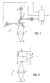
- the transmitter according to the invention has a plurality of semiconductor radiation sources, preferably three luminescence diodes in the blue, green and red spectral range, the optical radiation of which is brought together via a filter unit and directed onto the sample by a lens unit. Furthermore, a control unit is provided, which controls the individual semiconductor radiation sources one after the other in pulses, and a photoelectric emo receiver receives the reflected or transmitted radiation, a signal supplied by the control unit allowing the receiver signals to be assigned to the radiation emitted in the different spectral ranges.
- This arrangement according to the invention enables extremely rapid color detection to be achieved since the measurement cycle for all three colors can be less than 100 microseconds. The optical resolution is very large, so that even small characters can be captured.
- the arrangement according to the invention can be constructed in a very compact and maintenance-free manner, with extraneous light not impairing the measurements significantly or not at all.
- dichroic mirrors that is to say color separation filters, preferably a blue mirror and a red mirror
- the arrangement of the mirrors at an angle of 45 ° to the semiconductor radiation sources ensures that the red and blue radiation are deflected, while the green radiation is transmitted through the mirrors.
- excitation power can be specified separately in the pulsed control of the individual semiconductor radiation sources, so that the individual radiation sources can be calibrated in such a way that they produce measurement values defined on a standard at the radiation receiver.
- the transmitter and receiver is housed in a housing and their assignment in the housing is made in such a way that the receiver is at an angle of 45 ° to the radiation emitted by the transmitter, a color-effective scanning head is provided, which is particularly is small and maintenance free.
- the device for fast color measurement of different samples consists of a transmitter 1, which is connected to a control unit 2, a receiver 3 with a downstream evaluation unit 4, 5 and a computer connected to the evaluation unit.
- 1 has three light-emitting diodes 6, 7, 8, diode 6 emitting in the blue, diode 7 in the green and diode 8 in the red spectral range.
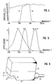
- the position of the emission spectra of the luminescent diodes 6, 7, 8 is shown in FIG. 5, it being evident that the maxima of the emitted radiation are around 480 nm (blue), 555 nm (green) and 670 nm (red).
- two dichroic mirrors 9, 10 forming color separation filters are connected, which are at an angle of 45 ° to the direction of radiation of the blue and red luminescent diodes 6, 8, so that the blue radiation of the luminescent diode 6 on the "Blauspiegel" 9 redirected and the red radiation the luminescence diode 8 is deflected at the "red mirror” 10 and is passed through the "blue mirror” 9.
- the green radiation from the luminescence diode 7 is transmitted through both the "red mirror” 10 and the "blue mirror” 9, so that the radiation from the individual diodes is combined into one radiation.
- This radiation is directed by a lens arrangement 11 onto or through the sample 12 to be measured.
- the individual optical elements, ie the luminescence diodes 6, 7, 8, the dichroic mirrors 9, 10 and the lens arrangement 11 are adjusted in such a way that the individual beams meet at a point at which the sample 12 must be located.
- Fig. 4 shows the transmission curves of the dichroic mirrors 9, 10, whereby it can be seen that the "blue mirror” 9 transmits the radiation from a wavelength of approx. 510 nm, i.e. the radiation is reflected in the blue area.
- the "red mirror” 10 which transmits the radiation up to about 610 nm and blocks the red area. This means that both the green and the red radiation are transmitted through the "blue mirror” 9, while the green and the blue radiation are transmitted through the "red mirror" 10.
- the radiation of the three luminescent diodes 6, 7, 8 can also be combined in another way, for example by means of radiation splitter plates and prism cubes, but the arrangement described forms the preferred exemplary embodiment.
- the receiver 3 according to FIG. 2 has a receiver optics 13, which collects the light reflected or transmitted by the sample 12 and brings it to the actual photo receiver 14, which can be designed, for example, as a photodiode.
- the photoreceiver 14 is selected such that it has a short response time and a high quantum efficiency.
- the photoreceiver 14 is connected to a signal amplifier 16 which is connected to a high-pass filter 15 and which suppresses low-frequency extraneous light interferences, for example from fluorescent lamps.
- the control and evaluation unit 17 is shown in FIG. 3, which of course has a power supply 18.
- the control unit 2 controls the transmitter 1 in pulses, i.e. each luminescent diode receives an excitation pulse of a fixed switch-on time, three pulses determining a cycle, i.e. with each cycle each luminescence diode 6, 7, 8 is addressed once and sends out one light pulse each.
- the control logic has a clock.
- control logic 2 sends out a synchronization signal that is available via line 19 at the output of the control and evaluation unit.
- the radiation pulses of high frequency reflected or transmitted by the sample are detected by the receiver 3 and converted into electrical pulses which the Evaluation unit are supplied, which has a sample and hold circuit 4, which stores the incoming pulses from the signal amplifier 16 for the duration of a cycle time.
- the sample and hold circuit 4 is followed by an A / D converter 5, which converts the color measurements corresponding to different voltages into digital values, for example into 8-bit values. These digital values are available at the output of the control and evaluation unit and are fed to a computer, not shown, which uses the synchronization signal to assign and process the measured values.
- the control unit 2 is designed such that the excitation power, i.e. The duration and level of the control pulses on the individual luminescent diodes 6, 7, 8 can be specified separately.
- the excitation power of the respective luminescent diodes 6, 7, 8 is set so that when using a standard, for example a white standard made of barium sulfate, defined output voltages, for example 2 V, are present at the receiver 3 in the reflection measurement.
- the result of one light pulse from each luminescence diode 6, 7, 8 is required, so that the single serial switching on of all luminescence diodes represents a measurement cycle and the minimum measurement time corresponds to the cycle time.
- this measuring cycle is ⁇ 100 ⁇ s, so that very fast measurements can be carried out.
- FIG. 6 shows a color measuring head used in the device according to the invention, in the housing 20 of which both the transmitter 1 and receiver 3 and the control and evaluation unit 17 are accommodated.
- a connecting line 26 leads to the computer (not shown).
- This color measuring head is to be used for remission measurements, whereby transmission measurements can also be carried out if a mirror is arranged behind the transparent sample.
- the base surface 21 of the housing 20 is provided with a shoulder 22, so that there is a surface 23 lying parallel to the base surface 21 and an inclined surface 24 connected to the base surface 21 is formed.
- the through openings to the transmitter and receiver or the lens arrangement 11, 13 for the transmitter and receiver are provided in the surfaces 23, 24.
- the inclined surface 24 preferably has an angle such that the reflectance measurement can be carried out at 45 °.
- the distance between the base 21 of the color measuring head and the base on which the sample 12 is located must be chosen so that the light spot 25 is as small as possible, namely preferably has a diameter of 1 mm. This distance can be filled by adjusting disks, which are to be placed under the base area 21.
Landscapes
- Physics & Mathematics (AREA)
- Spectroscopy & Molecular Physics (AREA)
- General Physics & Mathematics (AREA)
- Spectrometry And Color Measurement (AREA)
- Investigating Or Analysing Materials By Optical Means (AREA)
Applications Claiming Priority (2)
| Application Number | Priority Date | Filing Date | Title |
|---|---|---|---|
| DE19863626373 DE3626373A1 (de) | 1986-08-05 | 1986-08-05 | Vorrichtung zur schnellen farbmessung an unterschiedlichen proben |
| DE3626373 | 1986-08-05 |
Publications (3)
| Publication Number | Publication Date |
|---|---|
| EP0256970A2 EP0256970A2 (de) | 1988-02-24 |
| EP0256970A3 EP0256970A3 (en) | 1990-04-25 |
| EP0256970B1 true EP0256970B1 (de) | 1993-06-16 |
Family
ID=6306666
Family Applications (1)
| Application Number | Title | Priority Date | Filing Date |
|---|---|---|---|
| EP87730087A Expired - Lifetime EP0256970B1 (de) | 1986-08-05 | 1987-07-30 | Vorrichtung zur schnellen Farbmessung an unterschiedlichen Proben |
Country Status (3)
| Country | Link |
|---|---|
| US (1) | US4838697A (enExample) |
| EP (1) | EP0256970B1 (enExample) |
| DE (2) | DE3626373A1 (enExample) |
Cited By (1)
| Publication number | Priority date | Publication date | Assignee | Title |
|---|---|---|---|---|
| DE19511782A1 (de) * | 1995-03-30 | 1996-10-02 | Kurandt System Gmbh | Verfahren zur Prüfung von Farbdruckvorlagen und Vorrichtung zur Durchführung des Verfahrens |
Families Citing this family (30)
| Publication number | Priority date | Publication date | Assignee | Title |
|---|---|---|---|---|
| DE3879896D1 (de) * | 1987-12-03 | 1993-05-06 | Siemens Ag | Farbsensoranordnung fuer die erkennung von gegenstaenden mit farbigen oberflaechen. |
| GB8918605D0 (en) * | 1989-08-15 | 1989-09-27 | Mckeown Samuel T J | Shade distinguishing device |
| DE69124243T2 (de) * | 1990-07-25 | 1997-08-21 | Cerium Visual Technologies Ltd | Verfahren und vorrichtung zur erlangung einer gewünschten farbe |
| DD297241A5 (de) * | 1990-08-14 | 1992-01-02 | Technische Hochschule Leipzig,De | Verfahren zur punktualen ermittlung der spektralen remissionsfunktion mittels eines optoelektronischen farbmesskopfes |
| US5272518A (en) * | 1990-12-17 | 1993-12-21 | Hewlett-Packard Company | Colorimeter and calibration system |
| DE4103429A1 (de) * | 1991-02-05 | 1992-08-06 | Forschungsgesellschaft Fuer Dr | Photometer |
| US5303037A (en) * | 1992-02-24 | 1994-04-12 | Eaton Corporation | Color sensor illumination source employing a lightpipe and multiple LEDs |
| DE4420260C2 (de) * | 1994-06-10 | 1998-08-06 | Alfred Prof Dr Ing Leipertz | Verfahren zur Bestimmung von Farbwertanteilen und Farbsättigung |
| US5537211A (en) * | 1995-01-13 | 1996-07-16 | Triliance Corporation | Method and apparatus for selecting a wearable to match an object |
| DE29505165U1 (de) * | 1995-03-27 | 1995-05-18 | Erwin Sick Gmbh Optik-Elektronik, 79183 Waldkirch | Farbsensoranordnung zum Lesen farbiger Markierungen |
| DE19514199A1 (de) * | 1995-04-15 | 1996-10-17 | Jenoptik Technologie Gmbh | Anordnung zur Messung von Farben nicht selbstleuchtender Objekte |
| DE19535735C2 (de) * | 1995-09-26 | 2000-05-04 | Lehner Optoelectronic Gmbh | Optoelektronischer Lumineszenztaster |
| DE19640671C1 (de) * | 1996-10-02 | 1998-05-07 | Omron Electronics Mfg Of Germa | Dreibereichs-Verfahren zur analogen Farberkennung und Vorrichtung zum Durchführen des Verfahrens |
| US6117777A (en) * | 1997-07-30 | 2000-09-12 | Chartered Semiconductor Manufacturing Co. | Chemical mechanical polish (CMP) endpoint detection by colorimetry |
| DE29813763U1 (de) | 1997-09-26 | 1998-11-26 | Color Partner GmbH, 24223 Raisdorf | Farbmeßgerät |
| US6267722B1 (en) | 1998-02-03 | 2001-07-31 | Adeza Biomedical Corporation | Point of care diagnostic systems |
| US6394952B1 (en) * | 1998-02-03 | 2002-05-28 | Adeza Biomedical Corporation | Point of care diagnostic systems |
| USD434153S (en) * | 1998-04-20 | 2000-11-21 | Adeza Biomedical Corporation | Point of care analyte detector system |
| USD432244S (en) * | 1998-04-20 | 2000-10-17 | Adeza Biomedical Corporation | Device for encasing an assay test strip |
| BE1012272A5 (fr) * | 1998-11-06 | 2000-08-01 | Biophotonics Sa | Dispositif et procede de mesure d'images colorees. |
| DE19930688A1 (de) * | 1999-07-02 | 2001-01-04 | Byk Gardner Gmbh | Vorrichtung und Verfahren zur Bestimmung der Qualität von Oberflächen |
| US6620586B2 (en) | 2001-02-20 | 2003-09-16 | Applied Gene Technologies, Inc. | Methods and compositions for analyzing nucleic acids |
| CA2446368C (en) * | 2002-10-29 | 2014-10-14 | Bayer Healthcare Llc | Diffuse reflectance readhead |
| US6969180B2 (en) * | 2003-02-25 | 2005-11-29 | Ryan Waters | LED light apparatus and methodology |
| DE10315388B4 (de) * | 2003-04-04 | 2005-09-08 | Cgs Publishing Technologies International Gmbh | Verfahren zum Prüfen und Herstellen von Prüfdrucken |
| US7365854B2 (en) * | 2004-05-11 | 2008-04-29 | Nordson Corporation | Apparatus and methods for high speed RGB color discrimination |
| US7351245B2 (en) * | 2004-09-21 | 2008-04-01 | Bernice Joy Rozinsky | Apparatus and method for dislodging object from throat |
| CA2539679A1 (en) * | 2005-03-15 | 2006-09-15 | Electronic Design To Market, Inc. | System of measuring light transmission and/or reflection |
| US20080100839A1 (en) * | 2006-10-31 | 2008-05-01 | Fouquet Julie E | Method and system for measuring light propagating at multiple wavelengths |
| US8199324B2 (en) * | 2009-07-29 | 2012-06-12 | X-Rite, Inc. | Optical assemblies for a color measurement instrument |
Family Cites Families (11)
| Publication number | Priority date | Publication date | Assignee | Title |
|---|---|---|---|---|
| DD99439A1 (enExample) * | 1972-03-30 | 1973-08-13 | ||
| US3910701A (en) * | 1973-07-30 | 1975-10-07 | George R Henderson | Method and apparatus for measuring light reflectance absorption and or transmission |
| GB1547401A (en) * | 1976-01-12 | 1979-06-20 | Nekoosa Papers Inc | Measurement of optical properties of sheet material |
| JPS52141253A (en) * | 1976-05-19 | 1977-11-25 | Matsushita Electric Ind Co Ltd | Method and apparatus for color separatin |
| DE2710722A1 (de) * | 1977-03-11 | 1978-09-14 | Shigeru Suga | Farbmessgeraet mit einem filterspiegel |
| JPS53123986A (en) * | 1977-04-05 | 1978-10-28 | Omron Tateisi Electronics Co | Radiation method for measuring rays of hue inspection apparatus |
| FR2477705A1 (fr) * | 1980-03-05 | 1981-09-11 | David Michel | Procede et dispositif de mesure en colorimetrie |
| EP0081702A1 (en) * | 1981-11-25 | 1983-06-22 | Kollmorgen Technologies Corporation | Electro-optical system for color monitoring |
| DE3242219C1 (de) * | 1982-11-15 | 1984-02-16 | Erwin Sick Gmbh Optik-Elektronik, 7808 Waldkirch | Optisches Markenerkennungsgeraet |
| DE3401475A1 (de) * | 1984-01-18 | 1985-07-25 | I F M Internationale Fluggeräte und Motoren GmbH, 6940 Weinheim | Vorrichtung zur messung der farbe von gegenstaenden |
| DE3418839A1 (de) * | 1984-05-21 | 1985-11-21 | Hoelzle & Chelius GmbH, 6078 Neu Isenburg | Geraet zur kolorimetrie/photometrie |
-
1986
- 1986-08-05 DE DE19863626373 patent/DE3626373A1/de active Granted
-
1987
- 1987-07-30 DE DE8787730087T patent/DE3786208D1/de not_active Expired - Fee Related
- 1987-07-30 EP EP87730087A patent/EP0256970B1/de not_active Expired - Lifetime
- 1987-08-05 US US07/081,905 patent/US4838697A/en not_active Expired - Fee Related
Cited By (1)
| Publication number | Priority date | Publication date | Assignee | Title |
|---|---|---|---|---|
| DE19511782A1 (de) * | 1995-03-30 | 1996-10-02 | Kurandt System Gmbh | Verfahren zur Prüfung von Farbdruckvorlagen und Vorrichtung zur Durchführung des Verfahrens |
Also Published As
| Publication number | Publication date |
|---|---|
| DE3626373A1 (de) | 1988-02-18 |
| US4838697A (en) | 1989-06-13 |
| EP0256970A3 (en) | 1990-04-25 |
| EP0256970A2 (de) | 1988-02-24 |
| DE3786208D1 (de) | 1993-07-22 |
| DE3626373C2 (enExample) | 1991-04-25 |
Similar Documents
| Publication | Publication Date | Title |
|---|---|---|
| EP0256970B1 (de) | Vorrichtung zur schnellen Farbmessung an unterschiedlichen Proben | |
| DE3242219C1 (de) | Optisches Markenerkennungsgeraet | |
| DE19717488C2 (de) | Vorrichtung zur Inspektion der Oberfläche von Objekten | |
| DE3815375C2 (de) | Vorrichtung zum Erkennen eines Dokuments | |
| DE2533217A1 (de) | Verfahren und einrichtung zur ortung eines risses auf mindestens einer faser eines optischen kabels | |
| DE2722368A1 (de) | Sortiervorrichtung mit optischem abtaster | |
| EP0052813A2 (de) | Verfahren zum Beschauen einer reflektierenden und/oder transparenten, sich bewegenden Bahn und Beschaumaschine zur Durchführung des Verfahrens | |
| EP1189052A2 (de) | Vorrichtung zum bildlichen Erfassen von Stückgütern | |
| DE69104114T2 (de) | System zur Auswertung der optischen Dispersion. | |
| DE3418839A1 (de) | Geraet zur kolorimetrie/photometrie | |
| WO1992007250A1 (de) | Verfahren und vorrichtung zur automatisierten überwachung der herstellung von halbleiterbauteilen | |
| DE10000030A1 (de) | Kamerasystem für die Bearbeitung von Dokumenten | |
| DE3207479A1 (de) | Entfernungsmessvorrichtung | |
| EP0735501B1 (de) | Farbsensoranordnung zum Lesen farbiger Markierungen | |
| DE19608468C2 (de) | Optischer Abstandssensor | |
| DE3244286A1 (de) | Elektro-optische vorrichtung zum erkennen von farben | |
| DE3401475C2 (enExample) | ||
| DE10010834A1 (de) | Vorrichtung zur Präzisionsausrichtung von Wellen, Walzen, Achsen, Spindeln oder Werkzeugmaschinen | |
| EP0992771B2 (de) | Lichtkontrasttaster | |
| DE10137043A1 (de) | Vorrichtung zur Untersuchung von Wertdokumenten | |
| DE2713396A1 (de) | Verfahren und vorrichtung zur kennzeichnung oder identifizierung eines leuchtmaterial enthaltenden oder tragenden koerpers | |
| GB1150080A (en) | Apparatus for measuring a dimension of a body | |
| EP1207106A1 (de) | Verfahren und Vorrichtung zum Prüfen von Zigaretten | |
| EP1418399B1 (de) | Vorrichtung zum Vermessen von Werkzeugmaschinen | |
| EP1050843A2 (de) | Lunineszenztaster |
Legal Events
| Date | Code | Title | Description |
|---|---|---|---|
| PUAI | Public reference made under article 153(3) epc to a published international application that has entered the european phase |
Free format text: ORIGINAL CODE: 0009012 |
|
| AK | Designated contracting states |
Kind code of ref document: A2 Designated state(s): CH DE FR GB LI |
|
| PUAL | Search report despatched |
Free format text: ORIGINAL CODE: 0009013 |
|
| AK | Designated contracting states |
Kind code of ref document: A3 Designated state(s): CH DE FR GB LI |
|
| 17P | Request for examination filed |
Effective date: 19900919 |
|
| 17Q | First examination report despatched |
Effective date: 19920410 |
|
| GRAA | (expected) grant |
Free format text: ORIGINAL CODE: 0009210 |
|
| AK | Designated contracting states |
Kind code of ref document: B1 Designated state(s): CH DE FR GB LI |
|
| REF | Corresponds to: |
Ref document number: 3786208 Country of ref document: DE Date of ref document: 19930722 |
|
| GBT | Gb: translation of ep patent filed (gb section 77(6)(a)/1977) |
Effective date: 19930708 |
|
| ET | Fr: translation filed | ||
| PLBE | No opposition filed within time limit |
Free format text: ORIGINAL CODE: 0009261 |
|
| STAA | Information on the status of an ep patent application or granted ep patent |
Free format text: STATUS: NO OPPOSITION FILED WITHIN TIME LIMIT |
|
| 26N | No opposition filed | ||
| PGFP | Annual fee paid to national office [announced via postgrant information from national office to epo] |
Ref country code: DE Payment date: 20000718 Year of fee payment: 14 |
|
| PGFP | Annual fee paid to national office [announced via postgrant information from national office to epo] |
Ref country code: FR Payment date: 20000727 Year of fee payment: 14 |
|
| PGFP | Annual fee paid to national office [announced via postgrant information from national office to epo] |
Ref country code: GB Payment date: 20000811 Year of fee payment: 14 |
|
| PGFP | Annual fee paid to national office [announced via postgrant information from national office to epo] |
Ref country code: CH Payment date: 20000928 Year of fee payment: 14 |
|
| PG25 | Lapsed in a contracting state [announced via postgrant information from national office to epo] |
Ref country code: GB Free format text: LAPSE BECAUSE OF NON-PAYMENT OF DUE FEES Effective date: 20010730 |
|
| PG25 | Lapsed in a contracting state [announced via postgrant information from national office to epo] |
Ref country code: LI Free format text: LAPSE BECAUSE OF NON-PAYMENT OF DUE FEES Effective date: 20010731 Ref country code: CH Free format text: LAPSE BECAUSE OF NON-PAYMENT OF DUE FEES Effective date: 20010731 |
|
| REG | Reference to a national code |
Ref country code: CH Ref legal event code: PL |
|
| GBPC | Gb: european patent ceased through non-payment of renewal fee |
Effective date: 20010730 |
|
| PG25 | Lapsed in a contracting state [announced via postgrant information from national office to epo] |
Ref country code: FR Free format text: LAPSE BECAUSE OF NON-PAYMENT OF DUE FEES Effective date: 20020329 |
|
| PG25 | Lapsed in a contracting state [announced via postgrant information from national office to epo] |
Ref country code: DE Free format text: LAPSE BECAUSE OF NON-PAYMENT OF DUE FEES Effective date: 20020501 |
|
| REG | Reference to a national code |
Ref country code: FR Ref legal event code: ST |