EP0256830B1 - Maschine zum Formen von Konfigurationen an einem drehenden Werkstück - Google Patents
Maschine zum Formen von Konfigurationen an einem drehenden Werkstück Download PDFInfo
- Publication number
- EP0256830B1 EP0256830B1 EP87307072A EP87307072A EP0256830B1 EP 0256830 B1 EP0256830 B1 EP 0256830B1 EP 87307072 A EP87307072 A EP 87307072A EP 87307072 A EP87307072 A EP 87307072A EP 0256830 B1 EP0256830 B1 EP 0256830B1
- Authority
- EP
- European Patent Office
- Prior art keywords
- lever device
- tool
- clamping
- support surface
- bed
- Prior art date
- Legal status (The legal status is an assumption and is not a legal conclusion. Google has not performed a legal analysis and makes no representation as to the accuracy of the status listed.)
- Expired - Lifetime
Links
- 239000000969 carrier Substances 0.000 claims description 3
- 230000000630 rising effect Effects 0.000 claims description 2
- 239000002184 metal Substances 0.000 description 3
- 230000000295 complement effect Effects 0.000 description 2
- 238000002485 combustion reaction Methods 0.000 description 1
- 238000000034 method Methods 0.000 description 1
- 230000004048 modification Effects 0.000 description 1
- 238000012986 modification Methods 0.000 description 1
- 239000007787 solid Substances 0.000 description 1
Images
Classifications
-
- B—PERFORMING OPERATIONS; TRANSPORTING
- B21—MECHANICAL METAL-WORKING WITHOUT ESSENTIALLY REMOVING MATERIAL; PUNCHING METAL
- B21H—MAKING PARTICULAR METAL OBJECTS BY ROLLING, e.g. SCREWS, WHEELS, RINGS, BARRELS, BALLS
- B21H5/00—Making gear wheels, racks, spline shafts or worms
- B21H5/02—Making gear wheels, racks, spline shafts or worms with cylindrical outline, e.g. by means of die rolls
- B21H5/027—Making gear wheels, racks, spline shafts or worms with cylindrical outline, e.g. by means of die rolls by rolling using reciprocating flat dies, e.g. racks
-
- B—PERFORMING OPERATIONS; TRANSPORTING
- B21—MECHANICAL METAL-WORKING WITHOUT ESSENTIALLY REMOVING MATERIAL; PUNCHING METAL
- B21H—MAKING PARTICULAR METAL OBJECTS BY ROLLING, e.g. SCREWS, WHEELS, RINGS, BARRELS, BALLS
- B21H3/00—Making helical bodies or bodies having parts of helical shape
- B21H3/02—Making helical bodies or bodies having parts of helical shape external screw-threads ; Making dies for thread rolling
- B21H3/06—Making by means of profiled members other than rolls, e.g. reciprocating flat dies or jaws, moved longitudinally or curvilinearly with respect to each other
Definitions
- the invention relates to machines for forming configurations on or in a rotary workpiece, and particularly relates to apparatus for holding a forming tool of such a machine.
- the machines may be pressure forming machines, used for forming grooves, splines or gear teeth on a rotary shaft such as a gear or crank shaft of an internal combustion engine.
- the machines may be broach turning or cutting machines, in which a rack-like cutter is moved over a rotary workpiece to form a desired shape therein, for example a surface channel.
- EPO 181132 shows apparatus for holding a tool of a machine for pressure forming surface configurations on a rotary workpiece comprising an elongate support on which a tool is mountable, first automatic means for shifting the support longitudinally for adjusting the position of the tool and second automatic means for securing the support in a shifted position. It is an object of this invention to provide improved apparatus for holding a tool of a machine for pressure forming surface configurations on a rotary workpiece.
- apparatus for releasably clamping a tool for forming configurations on a rotary workpiece characterised in that it comprises: an elongate member having a bed and at least two support surfaces, rising from the bed in different planes; releasable clamping means comprising a lever device rotatably mounted on a spindle in the vicinity of a first support surface, the lever device having an engagement part shaped such that it can force a tool toward both the first support surface and a second support surface when the lever device is rotated in the clamping direction, which is the direction that moves the engagement part of the lever device towards the other support surface, the lever device also having a further part projecting away from the first-mentioned part; a slide means engageable with the lever device for rotation thereof in the clamping direction, the slide means having a wedge profile engageable with the further part of the lever device, and a biasing means connected to the lever device to bias said device away from the clamping direction.
- the slide may have a wedge profile engaging the further part.
- the slide means may be carried by an elongate carrier which may be reciprocable longitudinally by actuating means.
- the actuating means may comprise a hydraulic piston and cylinder arrangement.
- clamping means driven by the hydraulic cylinder which is a double-acting piston and cylinder arrangement having two coaxial carriers extending on either side of the cylinder to actuate the two clamping devices.
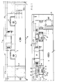
- apparatus 1 for holding a tool (not shown) of a rotary workpiece (that is one which rotates during the forming operation, though it could also rotate in use) comprising an elongate member 2 on which the tool is mountable and which member has a plurality of support surfaces 3 and 4, and means 5 to engage and urge the tool bodily against the support surfaces 3 and whereby to clamp the tool in an operative position.
- the means 5 in the embodiment shown is a rotatable lever device 6.
- lever devices 6 for each tool, and there are two tools in line, at 7 and 8, in upper and lower elongate members, of which the lower member 2 only is shown in the drawings.
- the devices 6 are identical and so only one will be described in detail.
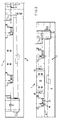
- the elongate member 2 in which each tool is mounted is identical in having a bed 9, which is inclined, with a heel 10 and toe plate 11 and heel/toe plate 12 which provide support surfaces 3 and 4 which rise at substantially 90° to one other from the bed 9.
- the lever device 6 is mounted in a recess 13 and has a part 14 which has a gear tooth surface profile or configuration 14 a and in use engages a complementary part of the tool.
- the lever device 6 is mounted on a spindle or shaft 15 for rotation, and has a further part 16 projecting away from the first-mentioned part 14 and which further part 16 is of bull-nose shape and is engageable by a slide means in the form of a wedge 17 to rotate the lever device 6.
- the wedge 17 is carried by an elongate carrier 18 which is reciprocable longitudinally by an actuating means in the form of a double acting piston and cylinder arrangement 19.
- the piston 19 is a hydraulic piston situated between the two respective lever devices 6 for each tool, the carriers 18 being carried by the piston rods 20.
- the devices 6 include biasing means 21 in the form of coil tension springs which bias the levers to the position shown in Figure 1.
- a tool for forming a configuration such as gear profiles in the surface of a rotary workpiece, such as a metal shaft, is an elongate metal block with transverse surface grooves in it so that it is in the form of a rack, and is known as such or as a rack cassette.
- the grooved surface would be uppermost when the rack is on the lower bed 2 shown.
- the rack is of generally square cross-section and in the rear (as considered in use) surface there are two channel-shaped blind slots, terminating at a position remote from the grooved surface, in other words adjacent the in use lower surface 9, in an enlarged part so that the channel is effectively of T-shape.
- the enlarged part has an angled and tapered surface profile which is effectively a camming surface of complementary shape to that of the gear tooth configuration 14 a of the projecting part 14 of the lever device 6.
- the piston and cylinder arrangement 19 is actuated to move the wedge 17 to rotate the lever device 6 so that that device is effectively at right angles to the surface 4.
- the tool is then offered up to the bed, above it, with the channels aligned with a respective part 14, and is then lowered to rest on the bed 9.
- the piston and cylinder arrangement 19 is then actuated to move the piston to the right as viewed in Figure 1.
- the female parts have non-return valves which are normally closed, but which are opened by the male parts, or drogues, to complete the hydraulic circuit so that there is thus a "solid" hydraulic connection throughout the system and it is therefore unnecessary to maintain hydraulic force and the wedges 17, which are effectively self-locking, remain in position to clamp the tool via the lever devices 6.
- a forming operation can then be carried out, usually by reciprocating the upper tools in unison longitudinally in an opposite direction to the lower tools while a workpiece between them is rotated. As many passes as are necessary are carried out to form the desired configuration.
- the operation is then repeated on a succeeding workpiece, and so on. If it is necessary to change a tool, for example because a different configuration is to be formed on a workpiece, or because a tool is worn, it is merely necessary to pressurize the cylinder of the piston and cylinder arrangement 19 to move the lever devices 6 to the substantially 90° position, when the tool can simply be slid clear and replaced by another one using the sequence already described.
- the apparatus thus provides a simple yet efficient method of interchangeability of tools in machines of the kind described.
Landscapes
- Engineering & Computer Science (AREA)
- Mechanical Engineering (AREA)
- Jigs For Machine Tools (AREA)
- Gripping On Spindles (AREA)
- Workshop Equipment, Work Benches, Supports, Or Storage Means (AREA)
Claims (6)
- Vorrichtung (1) zum lösbaren Einspannen eines Werkzeuges zum Herstellen von Konfigurationen an einem rotierenden Werkstück, dadurch gekennzeichnet, daß sie folgendes umfaßt:
ein längliches Element (2) mit einem Bett (9) und wenigstens zwei Stützflächen (3, 4), die sich in verschiedenen Ebenen von dem Bett (9) erheben;
lösbare Einspannmittel (5) mit einer Hebeleinrichtung (6), die in der Nähe einer ersten Stützfläche (4) drehbar auf einer Spindel (15) montiert ist, wobei die Hebeleinrichtung (6) ein Eingriffsteil (14) aufweist, das so geformt ist, daß es ein Werkzeug sowohl gegen die erste Stützfläche als auch gegen eine zweite Stützfläche (3) drücken kann, wenn die Hebeleinrichtung in Einspannrichtung gedreht wird, bei der es sich um die Richtung handelt, die das Eingriffsteil (14) der Hebeleinrichtung (6) zu der anderen Stützfläche (3) hin bewegt, wobei die Hebeleinrichtung (6) noch ein weiteres Teil (16) aufweist, das von dem erstgenannten Teil (14) wegragt;
ein Schiebermittel (17), das zur Drehung mit der Hebeleinrichtung (6) in Einspannrichtung in diese eingreifen kann, wobei das Schiebermittel (17) ein Keilprofil aufweist, das in das weitere Teil (16) der Hebeleinrichtung eingreifen kann, und ein Vorspannmittel (21), das mit der Hebeleinrichtung (6) verbunden ist, um die genannte Einrichtung (6) von der Einspannrichtung weg vorzuspannen. - Vorrichtung nach Anspruch 1, dadurch gekennzeichnet, daß das Teil (14) ein gezahntes Oberflächenprofil aufweist.
- Vorrichtung nach Anspruch 1 oder Anspruch 2, dadurch gekennzeichnet, daß das Vorspannmittel (21) eine Schraubenfeder umfaßt.
- Vorrichtung nach einem der vorhergehenden Ansprüche, dadurch gekennzeichnet, daß das Schiebermittel (17) von einem länglichen Träger (18) getragen wird, der von einem Betätigungsmittel (19) in Längsrichtung hin- und herbewegt werden kann.
- Vorrichtung nach Anspruch 4, dadurch gekennzeichnet, daß das Betätigungsmittel (19) eine Anordnung aus Hydraulikkolben und Zylinder aufweist.
- Vorrichtung nach Anspruch 5, dadurch gekennzeichnet, daß zwei voneinander beabstandete Einspannmittel (5) vorgesehen sind, die von einer doppeltwirkenden Kolben- und Zylinderanordnung (19) mit zwei koaxialen Trägern (18) angetrieben werden, die sich zur Betätigung der beiden Einspanneinrichtungen auf beiden Seiten des Zylinders erstrecken.
Applications Claiming Priority (2)
| Application Number | Priority Date | Filing Date | Title |
|---|---|---|---|
| GB8619554A GB2193669B (en) | 1986-08-11 | 1986-08-11 | Machines for forming configurations on a rotary workpiece |
| GB8619554 | 1986-08-11 |
Publications (3)
| Publication Number | Publication Date |
|---|---|
| EP0256830A2 EP0256830A2 (de) | 1988-02-24 |
| EP0256830A3 EP0256830A3 (en) | 1990-01-24 |
| EP0256830B1 true EP0256830B1 (de) | 1995-02-22 |
Family
ID=10602558
Family Applications (1)
| Application Number | Title | Priority Date | Filing Date |
|---|---|---|---|
| EP87307072A Expired - Lifetime EP0256830B1 (de) | 1986-08-11 | 1987-08-10 | Maschine zum Formen von Konfigurationen an einem drehenden Werkstück |
Country Status (4)
| Country | Link |
|---|---|
| EP (1) | EP0256830B1 (de) |
| DE (1) | DE3751079T2 (de) |
| ES (1) | ES2070821T3 (de) |
| GB (1) | GB2193669B (de) |
Citations (1)
| Publication number | Priority date | Publication date | Assignee | Title |
|---|---|---|---|---|
| US3791257A (en) * | 1972-03-27 | 1974-02-12 | Ind Inc | Machine tool tooling |
Family Cites Families (9)
| Publication number | Priority date | Publication date | Assignee | Title |
|---|---|---|---|---|
| US2392747A (en) * | 1943-08-23 | 1946-01-08 | American Broach & Machine Co | Pull head for broaching machines |
| DE898436C (de) * | 1950-12-23 | 1953-11-30 | Westfaelische Metall Ind G M B | Walzbacken fuer Gewindewalzmaschinen |
| US3183697A (en) * | 1962-01-02 | 1965-05-18 | Michigan Tool Co | Locating fixture |
| US3793866A (en) * | 1972-04-04 | 1974-02-26 | Anderson Cook Inc | Gear forming machines |
| US3818736A (en) * | 1972-10-10 | 1974-06-25 | Caterpillar Tractor Co | Tooth forming machine |
| DE2552441C2 (de) * | 1975-11-22 | 1982-07-22 | Kutscher, Hans-Werner, 3300 Braunschweig | Schnellspannvorrichtung zum Festspannen von Werkzeugen oder Werkstücken |
| US4028921A (en) * | 1976-02-13 | 1977-06-14 | Caterpillar Tractor Co. | Tooth forming rack with replaceable inserts |
| US4574605A (en) * | 1984-08-29 | 1986-03-11 | Ex-Cell-O Corporation | Forming machine with multiple work stations |
| GB8428220D0 (en) * | 1984-11-08 | 1984-12-19 | Gaston E Marbaix Ltd | Pressure forming surface configurations on rotary workpiece |
-
1986
- 1986-08-11 GB GB8619554A patent/GB2193669B/en not_active Expired - Lifetime
-
1987
- 1987-08-10 DE DE19873751079 patent/DE3751079T2/de not_active Expired - Fee Related
- 1987-08-10 ES ES87307072T patent/ES2070821T3/es not_active Expired - Lifetime
- 1987-08-10 EP EP87307072A patent/EP0256830B1/de not_active Expired - Lifetime
Patent Citations (1)
| Publication number | Priority date | Publication date | Assignee | Title |
|---|---|---|---|---|
| US3791257A (en) * | 1972-03-27 | 1974-02-12 | Ind Inc | Machine tool tooling |
Also Published As
| Publication number | Publication date |
|---|---|
| GB2193669A (en) | 1988-02-17 |
| EP0256830A2 (de) | 1988-02-24 |
| GB2193669B (en) | 1991-01-16 |
| GB8619554D0 (en) | 1986-09-24 |
| DE3751079T2 (de) | 1995-10-19 |
| ES2070821T3 (es) | 1995-06-16 |
| EP0256830A3 (en) | 1990-01-24 |
| DE3751079D1 (de) | 1995-03-30 |
Similar Documents
| Publication | Publication Date | Title |
|---|---|---|
| DE2805532C2 (de) | ||
| US4160372A (en) | Transfer press having quick change die sets | |
| EP0287986B1 (de) | Stanzvorrichtung für dünne Platten und in der Vorrichtung verwendete Stanzeinheiten | |
| EP0224792B1 (de) | Werkzeugwechseleinrichtung einer mehrstufigen Umformmaschine | |
| US4629384A (en) | Transfer and locator of workpieces for a gang machine | |
| DE4028446C1 (de) | ||
| EP0157728A1 (de) | Drehmaschine | |
| DE2204034B2 (de) | Vorrichtung zur spanabhebenden Bearbeitung scheibenförmiger Werkstücke | |
| DE3806116A1 (de) | Vorrichtung zum positionieren von bogenfoermigen kreuzsprossenrahmenteilen und zum fraesen von trapezfoermigen ausnehmungen in diese rahmenteile | |
| EP0256830B1 (de) | Maschine zum Formen von Konfigurationen an einem drehenden Werkstück | |
| DE1186295B (de) | Schalt- und Sperrgetriebe fuer insbesondere Spannfutter | |
| EP4266559A1 (de) | Bearbeitungsvorrichtung für leiteranordnungen an einem motor-blechpaket | |
| EP1063041A2 (de) | Werkzeugsystem für spannenden Metallbearbeitung von plattenförmigen Werkstücken | |
| DE2059838C2 (de) | Vorrichtung zum Steuerung der Ausspänbewegungen eines Bohrwerkzeuges | |
| DE2202805A1 (de) | Werkzeugmaschine zur spanabhebenden Bearbeitung | |
| US3834217A (en) | Pivotal clamping mechanism for die sets | |
| DE202004020654U1 (de) | Schwenkmaschine, insbesondere für Blechprofilmaterialien | |
| EP0925126B1 (de) | Bearbeitungsmaschine für plattenförmige werkstücke mit einem in einzelne segmente unterteilten niederhalter | |
| EP0173455A1 (de) | Bearbeitungsmaschine mit mehreren Umformwerkzeugstationen | |
| EP1331061A1 (de) | Spannvorrichtung | |
| DE20313816U1 (de) | Mittenspannvorrichtung | |
| EP0038199B1 (de) | Presse mit Revolverkopf | |
| JP4315477B2 (ja) | 個々に調節可能な工具を備えた順送り鍛造機 | |
| EP2958694A1 (de) | Schwenk-spannfutter | |
| DE3925452C1 (de) |
Legal Events
| Date | Code | Title | Description |
|---|---|---|---|
| PUAI | Public reference made under article 153(3) epc to a published international application that has entered the european phase |
Free format text: ORIGINAL CODE: 0009012 |
|
| AK | Designated contracting states |
Kind code of ref document: A2 Designated state(s): DE ES FR GB IT |
|
| RAP1 | Party data changed (applicant data changed or rights of an application transferred) |
Owner name: MARBAIX LAPOINTE LIMITED |
|
| PUAL | Search report despatched |
Free format text: ORIGINAL CODE: 0009013 |
|
| RHK1 | Main classification (correction) |
Ipc: B21H 3/06 |
|
| AK | Designated contracting states |
Kind code of ref document: A3 Designated state(s): DE ES FR GB IT |
|
| RAP1 | Party data changed (applicant data changed or rights of an application transferred) |
Owner name: MARBAIX LAPOINTE LIMITED |
|
| 17P | Request for examination filed |
Effective date: 19900612 |
|
| 17Q | First examination report despatched |
Effective date: 19911018 |
|
| GRAA | (expected) grant |
Free format text: ORIGINAL CODE: 0009210 |
|
| AK | Designated contracting states |
Kind code of ref document: B1 Designated state(s): DE ES FR GB IT |
|
| REF | Corresponds to: |
Ref document number: 3751079 Country of ref document: DE Date of ref document: 19950330 |
|
| ITF | It: translation for a ep patent filed | ||
| ET | Fr: translation filed | ||
| REG | Reference to a national code |
Ref country code: ES Ref legal event code: FG2A Ref document number: 2070821 Country of ref document: ES Kind code of ref document: T3 |
|
| PLBE | No opposition filed within time limit |
Free format text: ORIGINAL CODE: 0009261 |
|
| STAA | Information on the status of an ep patent application or granted ep patent |
Free format text: STATUS: NO OPPOSITION FILED WITHIN TIME LIMIT |
|
| 26N | No opposition filed | ||
| PGFP | Annual fee paid to national office [announced via postgrant information from national office to epo] |
Ref country code: GB Payment date: 19960801 Year of fee payment: 10 |
|
| PGFP | Annual fee paid to national office [announced via postgrant information from national office to epo] |
Ref country code: FR Payment date: 19960809 Year of fee payment: 10 |
|
| PGFP | Annual fee paid to national office [announced via postgrant information from national office to epo] |
Ref country code: DE Payment date: 19960816 Year of fee payment: 10 |
|
| PGFP | Annual fee paid to national office [announced via postgrant information from national office to epo] |
Ref country code: ES Payment date: 19960830 Year of fee payment: 10 |
|
| PG25 | Lapsed in a contracting state [announced via postgrant information from national office to epo] |
Ref country code: GB Free format text: LAPSE BECAUSE OF NON-PAYMENT OF DUE FEES Effective date: 19970810 |
|
| PG25 | Lapsed in a contracting state [announced via postgrant information from national office to epo] |
Ref country code: ES Free format text: LAPSE BECAUSE OF THE APPLICANT RENOUNCES Effective date: 19970811 |
|
| GBPC | Gb: european patent ceased through non-payment of renewal fee |
Effective date: 19970810 |
|
| PG25 | Lapsed in a contracting state [announced via postgrant information from national office to epo] |
Ref country code: FR Free format text: LAPSE BECAUSE OF NON-PAYMENT OF DUE FEES Effective date: 19980430 |
|
| PG25 | Lapsed in a contracting state [announced via postgrant information from national office to epo] |
Ref country code: DE Free format text: LAPSE BECAUSE OF NON-PAYMENT OF DUE FEES Effective date: 19980501 |
|
| REG | Reference to a national code |
Ref country code: FR Ref legal event code: ST |
|
| REG | Reference to a national code |
Ref country code: ES Ref legal event code: FD2A Effective date: 20001102 |
|
| PG25 | Lapsed in a contracting state [announced via postgrant information from national office to epo] |
Ref country code: IT Free format text: LAPSE BECAUSE OF NON-PAYMENT OF DUE FEES;WARNING: LAPSES OF ITALIAN PATENTS WITH EFFECTIVE DATE BEFORE 2007 MAY HAVE OCCURRED AT ANY TIME BEFORE 2007. THE CORRECT EFFECTIVE DATE MAY BE DIFFERENT FROM THE ONE RECORDED. Effective date: 20050810 |