EP0256830A2 - Machine pour former des configurations sur une pièce rotative - Google Patents
Machine pour former des configurations sur une pièce rotative Download PDFInfo
- Publication number
- EP0256830A2 EP0256830A2 EP87307072A EP87307072A EP0256830A2 EP 0256830 A2 EP0256830 A2 EP 0256830A2 EP 87307072 A EP87307072 A EP 87307072A EP 87307072 A EP87307072 A EP 87307072A EP 0256830 A2 EP0256830 A2 EP 0256830A2
- Authority
- EP
- European Patent Office
- Prior art keywords
- tool
- machine
- clamping
- lever device
- support surfaces
- Prior art date
- Legal status (The legal status is an assumption and is not a legal conclusion. Google has not performed a legal analysis and makes no representation as to the accuracy of the status listed.)
- Granted
Links
Images

Classifications
-
- B—PERFORMING OPERATIONS; TRANSPORTING
- B21—MECHANICAL METAL-WORKING WITHOUT ESSENTIALLY REMOVING MATERIAL; PUNCHING METAL
- B21H—MAKING PARTICULAR METAL OBJECTS BY ROLLING, e.g. SCREWS, WHEELS, RINGS, BARRELS, BALLS
- B21H5/00—Making gear wheels, racks, spline shafts or worms
- B21H5/02—Making gear wheels, racks, spline shafts or worms with cylindrical outline, e.g. by means of die rolls
- B21H5/027—Making gear wheels, racks, spline shafts or worms with cylindrical outline, e.g. by means of die rolls by rolling using reciprocating flat dies, e.g. racks
-
- B—PERFORMING OPERATIONS; TRANSPORTING
- B21—MECHANICAL METAL-WORKING WITHOUT ESSENTIALLY REMOVING MATERIAL; PUNCHING METAL
- B21H—MAKING PARTICULAR METAL OBJECTS BY ROLLING, e.g. SCREWS, WHEELS, RINGS, BARRELS, BALLS
- B21H3/00—Making helical bodies or bodies having parts of helical shape
- B21H3/02—Making helical bodies or bodies having parts of helical shape external screw-threads ; Making dies for thread rolling
- B21H3/06—Making by means of profiled members other than rolls, e.g. reciprocating flat dies or jaws, moved longitudinally or curvilinearly with respect to each other
Definitions
- the invention relates to machines for forming configurations on or in a rotary workpiece, and particularly relates to apparatus for holding a forming tool of such a machine.
- the machines may be pressure forming machines, used for forming grooves, splines or gear teeth on a rotary shaft such as a gear or crank shaft of an internal combustion engine.
- the machines may be broach turning or cutting machines, in which a rack-like cutter is moved over a rotary workpiece to form a desired shape therein, for example a surface channel.
- the invention provides apparatus for holding a tool of a machine for forming configurations of a rotary workpiece, comprising an elongate member on which a tool is mountable and which member has a plurality of support surfaces, and means to engage and urge the tool bodily against the support surfaces whereby to clamp the tool in an operative position.
- the means may comprise a rotatable lever device having a part which engages a complementary part of the tool.
- the part may have a gear-tooth surface profile.
- the lever device may be mounted for rotation on a spindle with a further part projecting away from the first-mentioned part and being engageable by a slide means to rotate the lever device.
- the slide may have a wedge profile engaging the further part.
- biasing means connected to the lever device to bias said device for rotation in a direction to disengage from the tool.
- the biasing means may comprise a coil spring.
- the slide means may be carried by an elongate carrier which may be reciprocable longitudinally by actuating means.
- the actuating means may comprise a hydraulic piston and cylinder arrangement.
- clamping means driven by the hydraulic cylinder which is a double-acting piston and cylinder arrangement having two coaxial carriers extending on either side of the cylinder to actuate the two clamping devices.
- a tool for forming configurations of a rotary workpiece comprising a surface profile for forming a desired configuration on a workpiece, surfaces for abutting support surfaces of a machine, and a clamping surface complementary to a device of the machine having a clamping surface so that when the complementary clamping surfaces are engaged, the tool is clamped in an operative position.
- the clamping surface may be part of a channel which is adapted to receive the device of the machine in a direction substantially at 90° to a bed of the machine.
- the invention also extends to a machine including apparatus and a tool as defined hereinbefore, in combination.
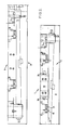
- apparatus 1 for holding a tool (not shown) of a rotary workpiece (that is one which rotates during the forming operation, though it could also rotate in use) comprising an elongate member 2 on which the tool is mountable and which member has a plurality of support surfaces 3 and 4, and means 5 to engage and urge the tool bodily against the support surfaces 3 and whereby to clamp the tool in an operative position.
- the means 5 in the embodiment shown is a rotatable lever device 6.
- lever devices 6 for each tool, and there are two tools in line, at 7 and 8, in upper and lower elongate members, of which the lower member 2 only is shown in the drawings.
- the devices 6 are identical and so only one will be described in detail.
- the elongate member 2 in which each tool is mounted is identical in having a bed 9, which is inclined, with a heel 10 and toe plate 11 and heel/toe plate 12 which provide support surfaces 3 and 4 which rise at substantially 90° to one other from the bed 9.
- the lever device 6 is mounted in a recess 13 and has a part 14 which has a gear tooth surface profile or configuration 14a and in use engages a complementary part of the tool.
- the lever device 6 is mounted on a spindle or shaft 15 for rotation, and has a further part 16 projecting away from the first-mentioned part 14 and which further part 16 is of bull-nose shape and is engageable by a slide means in the form of a wedge 17 to rotate the lever device 6.
- the wedge 17 is carried by an elongate carrier 18 which is reciprocable longitudinally by an actuating means in the form of a double acting piston and cylinder arrangement 19.
- the piston 19 is a hydraulic piston situated between the two respective lever devices 6 for each tool, the carriers 18 being carried by the piston rods 20.
- the devices 6 include biasing means 21 in the form of coil tension springs which bias the levers to the position shown in Figure 1.
- a tool for forming a configuration such as gear profiles in the surface of a rotary workpiece, such as a metal shaft, is an elongate metal block with transverse surface grooves in it so that it is in the form of a rack, and is known as such or as a rack cassette.
- the grooved surface would be uppermost when the rack is on the lower bed 2 shown.
- the rack is of generally square cross-section and in the rear (as considered in use) surface there are two channel-shaped blind slots, terminating at a position remote from the grooved surface, in other words adjacent the in use lower surface 9, in an enlarged part so that the channel is effectively of T-shape.
- the enlarged part has an angled and tapered surface profile which is effectively a camming surface of complementary shape to that of the gear tooth configuration 14a of the projecting part 14 of the lever device 6.
- the piston and cylinder arrangement 19 is actuated to move the wedge 17 to rotate the lever device 6 so that that device is effectively at right angles to the surface 4.
- the tool is then offered up to the bed, above it, with the channels aligned with a respective part 14, and is then lowered to rest on the bed 9.
- the piston and cylinder arrangement 19 is then actuated to move the piston to the right as viewed in Figure 1.
- the female parts have non-return valves which are normally closed, but which are opened by the male parts, or drogues, to complete the hydraulic circuit so that there is thus a "solid" hydraulic connection throughout the system and it is therefore unnecessary to maintain hydraulic force and the wedges 17, which are effectively self-locking, remain in position to clamp the tool via the lever devices 6.
- a forming operation can then be carried out, usually by reciprocating the upper tools in unison longitudinally in an opposite direction to the lower tools while a workpiece between them is rotated. As many passes as are necessary are carried out to form the desired configuration.
- the operation is then repeated on a succeeding workpiece, and so on. If it is necessary to change a tool, for example because a different configuration is to be formed on a workpiece, or because a tool is worn, it is merely necessary to pressurize the cylinder of the piston and cylinder arrangement 19 to move the lever devices 6 to the substantially 90° position, when the tool can simply be slid clear and replaced by another one using the sequence already described.
- the apparatus thus provides a simple yet efficient method of interchangeability of tools in machines of the kind described.
Landscapes
- Engineering & Computer Science (AREA)
- Mechanical Engineering (AREA)
- Jigs For Machine Tools (AREA)
- Gripping On Spindles (AREA)
- Workshop Equipment, Work Benches, Supports, Or Storage Means (AREA)
Applications Claiming Priority (2)
| Application Number | Priority Date | Filing Date | Title |
|---|---|---|---|
| GB8619554A GB2193669B (en) | 1986-08-11 | 1986-08-11 | Machines for forming configurations on a rotary workpiece |
| GB8619554 | 1986-08-11 |
Publications (3)
| Publication Number | Publication Date |
|---|---|
| EP0256830A2 true EP0256830A2 (fr) | 1988-02-24 |
| EP0256830A3 EP0256830A3 (en) | 1990-01-24 |
| EP0256830B1 EP0256830B1 (fr) | 1995-02-22 |
Family
ID=10602558
Family Applications (1)
| Application Number | Title | Priority Date | Filing Date |
|---|---|---|---|
| EP87307072A Expired - Lifetime EP0256830B1 (fr) | 1986-08-11 | 1987-08-10 | Machine pour former des configurations sur une pièce rotative |
Country Status (4)
| Country | Link |
|---|---|
| EP (1) | EP0256830B1 (fr) |
| DE (1) | DE3751079T2 (fr) |
| ES (1) | ES2070821T3 (fr) |
| GB (1) | GB2193669B (fr) |
Family Cites Families (10)
| Publication number | Priority date | Publication date | Assignee | Title |
|---|---|---|---|---|
| US2392747A (en) * | 1943-08-23 | 1946-01-08 | American Broach & Machine Co | Pull head for broaching machines |
| DE898436C (de) * | 1950-12-23 | 1953-11-30 | Westfaelische Metall Ind G M B | Walzbacken fuer Gewindewalzmaschinen |
| US3183697A (en) * | 1962-01-02 | 1965-05-18 | Michigan Tool Co | Locating fixture |
| US3791257A (en) * | 1972-03-27 | 1974-02-12 | Ind Inc | Machine tool tooling |
| US3793866A (en) * | 1972-04-04 | 1974-02-26 | Anderson Cook Inc | Gear forming machines |
| US3818736A (en) * | 1972-10-10 | 1974-06-25 | Caterpillar Tractor Co | Tooth forming machine |
| DE2552441C2 (de) * | 1975-11-22 | 1982-07-22 | Kutscher, Hans-Werner, 3300 Braunschweig | Schnellspannvorrichtung zum Festspannen von Werkzeugen oder Werkstücken |
| US4028921A (en) * | 1976-02-13 | 1977-06-14 | Caterpillar Tractor Co. | Tooth forming rack with replaceable inserts |
| US4574605A (en) * | 1984-08-29 | 1986-03-11 | Ex-Cell-O Corporation | Forming machine with multiple work stations |
| GB8428220D0 (en) * | 1984-11-08 | 1984-12-19 | Gaston E Marbaix Ltd | Pressure forming surface configurations on rotary workpiece |
-
1986
- 1986-08-11 GB GB8619554A patent/GB2193669B/en not_active Expired - Lifetime
-
1987
- 1987-08-10 DE DE19873751079 patent/DE3751079T2/de not_active Expired - Fee Related
- 1987-08-10 ES ES87307072T patent/ES2070821T3/es not_active Expired - Lifetime
- 1987-08-10 EP EP87307072A patent/EP0256830B1/fr not_active Expired - Lifetime
Also Published As
| Publication number | Publication date |
|---|---|
| GB2193669A (en) | 1988-02-17 |
| EP0256830B1 (fr) | 1995-02-22 |
| GB2193669B (en) | 1991-01-16 |
| GB8619554D0 (en) | 1986-09-24 |
| DE3751079T2 (de) | 1995-10-19 |
| ES2070821T3 (es) | 1995-06-16 |
| EP0256830A3 (en) | 1990-01-24 |
| DE3751079D1 (de) | 1995-03-30 |
Similar Documents
| Publication | Publication Date | Title |
|---|---|---|
| US4160372A (en) | Transfer press having quick change die sets | |
| DE2805532C2 (fr) | ||
| EP0287986B1 (fr) | Dispositif de poinçonnage pour des plaques minces et éléments de poinçonnage utilisés dans ce dispositif | |
| EP0224792B1 (fr) | Dispositif de changement d'outils pour une machine de formage à étages multiples | |
| US4629384A (en) | Transfer and locator of workpieces for a gang machine | |
| AT400823B (de) | Revolverstanzpresse und verfahren zum positionieren von stempeln in einer revolverstanzpresse | |
| DE2204034B2 (de) | Vorrichtung zur spanabhebenden Bearbeitung scheibenförmiger Werkstücke | |
| DE3806116A1 (de) | Vorrichtung zum positionieren von bogenfoermigen kreuzsprossenrahmenteilen und zum fraesen von trapezfoermigen ausnehmungen in diese rahmenteile | |
| EP4266559A1 (fr) | Dispositif d'usinage pour des dispositifs conducteurs sur un paquet de tôles de moteur | |
| EP0258594B1 (fr) | Dispositif de serrage pour anneaux de palier dans des moyeux de bride | |
| EP0256830B1 (fr) | Machine pour former des configurations sur une pièce rotative | |
| CN87105415A (zh) | 一种加工工件的方法和装置以及一种夹持该工件的夹具 | |
| DE202004020654U1 (de) | Schwenkmaschine, insbesondere für Blechprofilmaterialien | |
| US3834217A (en) | Pivotal clamping mechanism for die sets | |
| EP0623420B1 (fr) | Dispositif de transport et de fixation | |
| EP1331061A1 (fr) | Dispositif de serrage | |
| DE20313816U1 (de) | Mittenspannvorrichtung | |
| EP1329283A2 (fr) | Système de serrage | |
| EP1334803B1 (fr) | Dispositif de serrage, notamment étau | |
| EP0038199B1 (fr) | Presse rotative | |
| DE3925452C1 (fr) | ||
| EP2958694A1 (fr) | Mandrin de serrage pivotant | |
| US5374041A (en) | Vise | |
| CN115889854B (zh) | 一种人防门扇面板加工钻孔工装板 | |
| DE3425317A1 (de) | Nc-gesteuerte lochstanzmaschine fuer rohre |
Legal Events
| Date | Code | Title | Description |
|---|---|---|---|
| PUAI | Public reference made under article 153(3) epc to a published international application that has entered the european phase |
Free format text: ORIGINAL CODE: 0009012 |
|
| AK | Designated contracting states |
Kind code of ref document: A2 Designated state(s): DE ES FR GB IT |
|
| RAP1 | Party data changed (applicant data changed or rights of an application transferred) |
Owner name: MARBAIX LAPOINTE LIMITED |
|
| PUAL | Search report despatched |
Free format text: ORIGINAL CODE: 0009013 |
|
| RHK1 | Main classification (correction) |
Ipc: B21H 3/06 |
|
| AK | Designated contracting states |
Kind code of ref document: A3 Designated state(s): DE ES FR GB IT |
|
| RAP1 | Party data changed (applicant data changed or rights of an application transferred) |
Owner name: MARBAIX LAPOINTE LIMITED |
|
| 17P | Request for examination filed |
Effective date: 19900612 |
|
| 17Q | First examination report despatched |
Effective date: 19911018 |
|
| GRAA | (expected) grant |
Free format text: ORIGINAL CODE: 0009210 |
|
| AK | Designated contracting states |
Kind code of ref document: B1 Designated state(s): DE ES FR GB IT |
|
| REF | Corresponds to: |
Ref document number: 3751079 Country of ref document: DE Date of ref document: 19950330 |
|
| ITF | It: translation for a ep patent filed | ||
| ET | Fr: translation filed | ||
| REG | Reference to a national code |
Ref country code: ES Ref legal event code: FG2A Ref document number: 2070821 Country of ref document: ES Kind code of ref document: T3 |
|
| PLBE | No opposition filed within time limit |
Free format text: ORIGINAL CODE: 0009261 |
|
| STAA | Information on the status of an ep patent application or granted ep patent |
Free format text: STATUS: NO OPPOSITION FILED WITHIN TIME LIMIT |
|
| 26N | No opposition filed | ||
| PGFP | Annual fee paid to national office [announced via postgrant information from national office to epo] |
Ref country code: GB Payment date: 19960801 Year of fee payment: 10 |
|
| PGFP | Annual fee paid to national office [announced via postgrant information from national office to epo] |
Ref country code: FR Payment date: 19960809 Year of fee payment: 10 |
|
| PGFP | Annual fee paid to national office [announced via postgrant information from national office to epo] |
Ref country code: DE Payment date: 19960816 Year of fee payment: 10 |
|
| PGFP | Annual fee paid to national office [announced via postgrant information from national office to epo] |
Ref country code: ES Payment date: 19960830 Year of fee payment: 10 |
|
| PG25 | Lapsed in a contracting state [announced via postgrant information from national office to epo] |
Ref country code: GB Free format text: LAPSE BECAUSE OF NON-PAYMENT OF DUE FEES Effective date: 19970810 |
|
| PG25 | Lapsed in a contracting state [announced via postgrant information from national office to epo] |
Ref country code: ES Free format text: LAPSE BECAUSE OF THE APPLICANT RENOUNCES Effective date: 19970811 |
|
| GBPC | Gb: european patent ceased through non-payment of renewal fee |
Effective date: 19970810 |
|
| PG25 | Lapsed in a contracting state [announced via postgrant information from national office to epo] |
Ref country code: FR Free format text: LAPSE BECAUSE OF NON-PAYMENT OF DUE FEES Effective date: 19980430 |
|
| PG25 | Lapsed in a contracting state [announced via postgrant information from national office to epo] |
Ref country code: DE Free format text: LAPSE BECAUSE OF NON-PAYMENT OF DUE FEES Effective date: 19980501 |
|
| REG | Reference to a national code |
Ref country code: FR Ref legal event code: ST |
|
| REG | Reference to a national code |
Ref country code: ES Ref legal event code: FD2A Effective date: 20001102 |
|
| PG25 | Lapsed in a contracting state [announced via postgrant information from national office to epo] |
Ref country code: IT Free format text: LAPSE BECAUSE OF NON-PAYMENT OF DUE FEES;WARNING: LAPSES OF ITALIAN PATENTS WITH EFFECTIVE DATE BEFORE 2007 MAY HAVE OCCURRED AT ANY TIME BEFORE 2007. THE CORRECT EFFECTIVE DATE MAY BE DIFFERENT FROM THE ONE RECORDED. Effective date: 20050810 |