EP0255873A2 - Device to adjust and fix the level of a vehicle roof cover - Google Patents
Device to adjust and fix the level of a vehicle roof cover Download PDFInfo
- Publication number
- EP0255873A2 EP0255873A2 EP87109775A EP87109775A EP0255873A2 EP 0255873 A2 EP0255873 A2 EP 0255873A2 EP 87109775 A EP87109775 A EP 87109775A EP 87109775 A EP87109775 A EP 87109775A EP 0255873 A2 EP0255873 A2 EP 0255873A2
- Authority
- EP
- European Patent Office
- Prior art keywords
- screw
- roof
- threaded
- guide frame
- adjusting screw
- Prior art date
- Legal status (The legal status is an assumption and is not a legal conclusion. Google has not performed a legal analysis and makes no representation as to the accuracy of the status listed.)
- Withdrawn
Links
Images
Classifications
-
- B—PERFORMING OPERATIONS; TRANSPORTING
- B60—VEHICLES IN GENERAL
- B60J—WINDOWS, WINDSCREENS, NON-FIXED ROOFS, DOORS, OR SIMILAR DEVICES FOR VEHICLES; REMOVABLE EXTERNAL PROTECTIVE COVERINGS SPECIALLY ADAPTED FOR VEHICLES
- B60J7/00—Non-fixed roofs; Roofs with movable panels, e.g. rotary sunroofs
- B60J7/02—Non-fixed roofs; Roofs with movable panels, e.g. rotary sunroofs of sliding type, e.g. comprising guide shoes
- B60J7/024—Non-fixed roofs; Roofs with movable panels, e.g. rotary sunroofs of sliding type, e.g. comprising guide shoes characterised by the height regulating mechanism of the sliding panel
Definitions
- the invention relates to a device for adjusting and fixing the height of an optional closing and at least partially releasing a roof section of a fixed roof surface of a vehicle with respect to the fixed roof surface, with a guide frame supporting the cover via a cover actuating device, which is under at least one the fixed roof surface fixed reinforcement part is arranged and connected to this height adjustable via screw members, the axis of which is perpendicular or almost perpendicular.
- the screw members each comprise a nut seated on the reinforcing part, into which a screw is screwed from below, which passes through the corresponding through holes of the guide frame and the reinforcing part and onto which between the guide frame and spacers in the required number and / or thickness are attached to the reinforcing part in order to adjust the height of the cover to the fixed roof surface.
- the height adjustment of the cover is relatively labor-intensive and time-consuming, since it has to be tried out or measured how many spacers are necessary in each case, and since these spacers then have to be introduced between the guide frame and the reinforcing part in a complicated manner.
- the invention specified in claim 1 has for its object to provide a device of the type mentioned, which further simplifies assembly and height adjustment and is also suitable for robot assembly.
- the screw members each have a threaded bushing attached to the guide frame with a continuous threaded opening, an adjusting screw provided with a through hole and screwed into the threaded opening of the threaded bushing, with its upper end projecting upward from the threaded bushing on the underside of the reinforcing part, and have a fastening screw inserted into the through hole of the adjusting screw, the end of which protrudes upward from the through hole of the adjusting screw into a threaded bore of the reinforcing part, the adjusting screw and the fastening screw being designed for adjustment from below.
- the height adjustment of the guide frame is carried out by correspondingly turning the adjusting screw which specifies the mutual height distance between the reinforcing part and the guide frame in that it is in threaded engagement with the threaded bushing of the guide frame and at the same time abuts against the underside of the reinforcing part.
- the arrangement is fixed by tightening the fastening screw, the fastening screw also serving to hang the guide frame on the reinforcing part in question.
- the height adjustment can be carried out precisely and continuously. Adjustment and mounting screws are easily accessible; for this reason and also because no additional elements, such as spacers or the like, need to be introduced, the device according to the invention is eminently suitable for robot assembly.
- the height adjustment screw members with additional fastening screw are known from DE-GM 17 64 070. Apart from the fact that these screw members are located between the roof-mounted guide rails of a sliding roof and the cover actuating device or between the cover and sliding pieces which can be displaced along the guide rails the fastening screw is screwed into a first threaded bushing which is attached to one of the mutually height-adjustable components and onto which a second threaded bushing is screwed which is supported against the other of the mutually height-adjustable components. The second threaded bushing must be turned to adjust the height. This is difficult because the second threaded bushing sits between the two components that are height-adjustable relative to one another and is consequently only accessible from the side.
- a reinforcing part is provided in a manner known per se, a roof reinforcing frame that surrounds the roof cutout at least at the front and laterally.
- the threaded bushings can expediently be attached to an outwardly projecting fastening flange of the guide frame. If the guide frame is made of plastic, threaded bushings, for example made of metal, can be embedded in the guide frame during its manufacture. If necessary, the threaded bushing can also be formed by the mounting frame of the guide flange itself.
- the arrangement is such that the adjusting screw projects downward with its lower end from the threaded bushing and carries a head for rotating the adjusting screw at its lower end.
- the lower end of the fastening screw can protrude downward from the through hole of the adjusting screw and a head can be used to turn the fastening screw at its lower end.
- the head of the adjusting screw advantageously has a downwardly opening recess for at least partially receiving the head of the fastening screw.
- a seal for mutually sealing the guide frame and the roof reinforcement frame is expediently arranged on the side of the screw members facing the roof cutout.
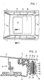
- a roof cutout 11 is provided in a fixed roof surface 10 of a motor vehicle.
- the roof cutout 11 can optionally be closed by means of a cover 12 or at least partially exposed.
- the cover 12 can be part of a sliding roof, a lifting roof, a sliding / lifting roof, a spoiler roof, a slatted roof, or the like in a known manner.
- the lid 12 is supported on a guide frame 14 by any lid actuating device of known type, which is only indicated schematically in FIG. 2 at 13.
- the roof cutout 11 is encompassed at least at the front and at the side by a roof reinforcement frame 15 seated under the fixed roof surface 10, which can be glued or spot welded to the fixed roof surface 10, for example.
- the guide frame 14 is connected to the roof reinforcement frame 15 in a height-adjustable manner by means of screw members designated overall by 16.
- the guide frame 14 has an outwardly projecting fastening flange 17, in which threaded bushings 18 forming parts of the screw members 16 are integrated at several locations distributed in the circumferential direction, for example in the case of a plastic guide frame, are embedded therein.
- Each threaded bushing 18 has a continuous threaded opening 19, the axis of which is perpendicular or almost vertical.
- An adjusting screw 20 is screwed into the threaded opening 19 and is provided with a through hole 21.
- the adjusting screw 20 is supported with its upper end projecting upward from the threaded bushing 18 on the underside of a flange 22 of the roof reinforcement frame 15.
- the flange 22 is vertically spaced below the fixed roof surface 10.
- a fastening screw 23 is inserted into the through hole 21.
- the end of the fastening screw 23 projecting upward from the through bore 21 is in screw engagement with a threaded bore 24 in the flange 22 of the roof reinforcement frame 15.
- the adjusting screw 20 carries a head 25 at its lower end projecting downward from the threaded bushing 18, while that from the Through hole 21 of the adjusting screw 20 projecting downward end of the fastening screw 23 is provided with a head 26.
- a recess 27 is formed, which opens downwards and which partially receives the head 26 of the tightened fastening screw 23 (FIG. 2).
- the guide frame 14 carries on the side of the fastening flange 17 facing the roof cutout 11 a seal 30 which, in the fully assembled state, bears sealingly against the roof reinforcement frame 15 from below.
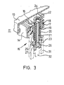
- the cover 12 and the cover actuating device 13 can be completely mounted on the guide frame 14 and functionally tested.
- the upper ends of the adjusting screws 20 are expediently flush with the top of the threaded bushings 18 and the fastening flange 17.
- this unit can be mounted, for example, on compression springs in a mounting device be, which presses the mounting flange 17 of the guide frame 14 against the flange 22 of the roof reinforcement frame 15. The entire unit is pressed downwards against the spring pressure of the mounting device by screwing in the adjusting screws 20 by means of a tool indicated at 31 in FIG. 3.
- the cover 12 mounted on the guide frame 14 is thereby adjusted downwards.
- the fastening screws 23 are screwed into the threaded bores 24 of the flange 22 of the roof reinforcement frame 15 by means of a tool indicated at 32.
- the unit consisting of cover 12, cover actuation device 13 and guide frame 14 is connected to the roof reinforcement frame 15.
- the position of the adjusting screws 20 is fixed.
- the illustrated embodiment can be modified, inter alia, in such a way that the roof reinforcement frame is provided with threaded bushes or nuts for receiving the fastening screws 23. If necessary, the threaded bushings 18 can also be formed directly from the material of the fastening flange 17.
Abstract
Description
Die Erfindung bezieht sich auf eine Vorrichtung zum Einstellen und Fixieren der Höhenlage eines dem wahlweisen Verschließen und mindestens teilweisen Freigeben eines Dachausschnitts einer festen Dachfläche eines Fahrzeugs dienenden Deckels gegenüber der festen Dachfläche, mit einem den Deckel über eine Deckelbetätigungseinrichtung tragenden Führungsrahmen, der unter mindestens einem an der festen Dachfläche befestigten Verstärkungsteil angeordnet und mit diesem über Schraubglieder höhenverstellbar verbunden ist, deren Achse lotrecht oder nahezu lotrecht verläuft.The invention relates to a device for adjusting and fixing the height of an optional closing and at least partially releasing a roof section of a fixed roof surface of a vehicle with respect to the fixed roof surface, with a guide frame supporting the cover via a cover actuating device, which is under at least one the fixed roof surface fixed reinforcement part is arranged and connected to this height adjustable via screw members, the axis of which is perpendicular or almost perpendicular.
Bei einer bekannten Vorrichtung dieser Art (DE-AS 11 61 155) umfassen die Schraubglieder jeweils eine auf dem Verstärkungsteil sitzende Mutter, in die von unten eine Schraube eingeschraubt wird, die entsprechende Durchgangslöcher des Führungsrahmens und des Verstärkungsteils durchgreift und auf die zwischen dem Führungsrahmen und dem Verstärkungsteil Distanzscheiben in der jeweils erforderlichen Anzahl und/oder Dicke aufgesteckt werden, um die Höhenlage des Deckels an die feste Dachfläche anzugleichen. Bei der bekannten Vorrichtung gestaltet sich die Höheneinstellung des Deckels relativ arbeits-und zeitaufwendig, da ausprobiert oder ausgemessen werden muß, wieviele Distanzscheiben jeweils notwendig sind, und da diese Distanzscheiben dann in umständlicher Weise zwischen den Führungsrahmen und das Verstärkungsteil eingebracht werden müssen. Es ist auch bekannt (DE-PS 949 446), bei einem Fahrzeugschiebedach einen den Dachausschnitt umgreifenden Regenrinnenrahmen an einem an der festen Dachfläche befestigten Dachverstärkungsrahmen in der Weise höheneinstellbar anzuordnen, daß aneinander anliegende, lotrecht verlaufende Streifen des Regenrinnenrahmens und des Dachverstärkungsrahmens mit Langlöchern versehen sind, deren längere Abmessung in lotrechter Richtung verläuft und durch die eine Klemmschraube gesteckt ist. Auf die Klemmschraube ist eine Flügelmutter aufgeschraubt, durch deren Anziehen die Streifen in Klemmeingriff miteinander gebracht werden. Dabei besteht jedoch die Gefahr, daß sich die Klemmverbindungen lockern. Infolgedessen sind diese bei der bekannten Vorrichtung nur als Montagehilfe vorgesehen, und der Regenrinnenrahmen wird dort nach der Höheneinstellung mit dem Dachverstärkungsrahmen zusätzlich punktverschweißt, verschraubt oder vernietet. Hinzu kommt, daß die vorerwähnten bekannten Vorrichtungen nicht für eine Robotermontage eines Schiebe-, Hebe-, Schiebehebedaches oder dergleichen in der Fahrzeugkarrosserie geeignet sind.In a known device of this type (DE-AS 11 61 155), the screw members each comprise a nut seated on the reinforcing part, into which a screw is screwed from below, which passes through the corresponding through holes of the guide frame and the reinforcing part and onto which between the guide frame and spacers in the required number and / or thickness are attached to the reinforcing part in order to adjust the height of the cover to the fixed roof surface. In the known device, the height adjustment of the cover is relatively labor-intensive and time-consuming, since it has to be tried out or measured how many spacers are necessary in each case, and since these spacers then have to be introduced between the guide frame and the reinforcing part in a complicated manner. It is also known (DE-PS 949 446) to arrange in a vehicle sunroof a gutter frame encompassing the roof cutout on a roof reinforcement frame attached to the fixed roof surface in such a way that adjacent, perpendicular strips of the gutter frame and the roof reinforcement frame are provided with elongated holes , whose longer dimension runs in the vertical direction and through which a clamping screw is inserted. A wing nut is screwed onto the clamping screw, the tightening of which brings the strips into clamping engagement with one another. However, there is a risk that the clamp connections will loosen. As a result, these are provided in the known device only as an assembly aid, and the gutter frame is additionally spot welded, screwed or riveted to the roof reinforcement frame after the height adjustment. In addition, the aforementioned known devices are not suitable for robot assembly of a sliding, lifting, sliding / lifting roof or the like in the vehicle body.
Der im Anspruch 1 angegebenen Erfindung liegt die Aufgabe zugrunde, eine Vorrichtung der eingangs genannten Art zu schaffen, welche die Montage und Höheneinstellung weiter vereinfacht und auch für eine Robotermontage geeignet ist.The invention specified in claim 1 has for its object to provide a device of the type mentioned, which further simplifies assembly and height adjustment and is also suitable for robot assembly.
Diese Aufgabe wird erfindungsgemäß dadurch gelöst, daß die Schraubglieder jeweils eine an dem Führungsrahmen angebrachte Gewindebuchse mit durchgehender Gewindeöffnung, eine mit einer Durchgangsbohrung versehene , in die Gewindeöffnung der Gewindebuchse eingeschraubte Einstellschraube, die sich mit ihrem aus der Gewindebuchse nach oben vorstehenden oberen Ende an der Unterseite des Verstärkungsteils abstützt, und eine in die Durchgangsbohrung der Einstellschraube eingesteckte Befestigungsschraube aufweisen, deren aus der Durchgangsbohrung der Einstellschraube nach oben vorstehendes Ende in eine Gewindebohrung des Verstärkungsteils eingeschraubt ist, wobei die Einstellschraube und die Befestigungsschraube zum Verstellen von unten ausgebildet sind.This object is achieved in that the screw members each have a threaded bushing attached to the guide frame with a continuous threaded opening, an adjusting screw provided with a through hole and screwed into the threaded opening of the threaded bushing, with its upper end projecting upward from the threaded bushing on the underside of the reinforcing part, and have a fastening screw inserted into the through hole of the adjusting screw, the end of which protrudes upward from the through hole of the adjusting screw into a threaded bore of the reinforcing part, the adjusting screw and the fastening screw being designed for adjustment from below.
Bei der Vorrichtung nach der Erfindung erfolgt die Höheneinstellung des Führungsrahmens durch entsprechendes Verdrehen der Einstellschraube, welche den gegenseitigen Höhenabstand zwischen dem Verstärkungsteil und dem Führungsrahmen dadurch vorgibt, daß sie mit der Gewindebuchse des Führungsrahmens in Gewindeeingriff steht und sich gleichzeitig gegen die Unterseite des Verstärkungsteils anlegt. Nach erfolgter Höhenjustierung wird die Anordnung durch Anziehen der Befestigungsschraube fixiert, wobei die Be festigungsschraube gleichzeitig dem Aufhängen des Führungsrahmens an dem betreffenden Verstärkungsteil dient. Die Höhenjustierung kann genau und stufenlos vorgenommen werden. Einstell-und Befestigungsschraube sind leicht zugänglich; deshalb und auch weil keine Zusatzelemente, wie Distanzscheiben oder dergleichen, eingebracht zu werden brauchen, eignet sich die erfindungsgemäße Vorrichtung hervorragend für eine Robotermontage.In the device according to the invention, the height adjustment of the guide frame is carried out by correspondingly turning the adjusting screw which specifies the mutual height distance between the reinforcing part and the guide frame in that it is in threaded engagement with the threaded bushing of the guide frame and at the same time abuts against the underside of the reinforcing part. After the height adjustment, the arrangement is fixed by tightening the fastening screw, the fastening screw also serving to hang the guide frame on the reinforcing part in question. The height adjustment can be carried out precisely and continuously. Adjustment and mounting screws are easily accessible; for this reason and also because no additional elements, such as spacers or the like, need to be introduced, the device according to the invention is eminently suitable for robot assembly.
Der Höheneinstellung dienende Schraubglieder mit zusätzlicher Befestigungsschraube sind zwar aus dem DE-GM 17 64 070 bekannt. Abgesehen davon, daß diese Schraubglieder dort zwischen dachfesten Führungsschienen eines Schiebedaches und der Deckelbetätigungsvorrichtung bzw. zwischen dem Deckel und entlang den Führungsschienen verschiebbaren Gleitstücken sitzen, ist die Befestigungsschraube in eine erste Gewindebuchse eingeschraubt, die an einem der gegeneinander höhenverstellbaren Bauteile angebracht ist und auf die eine zweite Gewindebuchse aufgeschraubt ist, die sich gegen das andere der gegeneinander höhenverstellbaren Bauteile abstützt. Dabei muß zur Höhenjustierung die zweite Gewindebuchse gedreht werden. Dies ist schwierig, weil die zweite Gewindebuchse zwischen den beiden gegeneinander höhenverstellbaren Bauteilen sitzt und infolgedessen nur seitlich zugänglich ist.The height adjustment screw members with additional fastening screw are known from DE-GM 17 64 070. Apart from the fact that these screw members are located between the roof-mounted guide rails of a sliding roof and the cover actuating device or between the cover and sliding pieces which can be displaced along the guide rails the fastening screw is screwed into a first threaded bushing which is attached to one of the mutually height-adjustable components and onto which a second threaded bushing is screwed which is supported against the other of the mutually height-adjustable components. The second threaded bushing must be turned to adjust the height. This is difficult because the second threaded bushing sits between the two components that are height-adjustable relative to one another and is consequently only accessible from the side.
Grundsätzlich können mehrere einzelne, beispielsweise bügelförmige Verstärkungsteile vorgesehen sein, die in geeigneter Weise um den Umfang des Dachausschnittes verteilt sind. Vorzugsweise ist jedoch als Verstärkungsteil in an sich bekannter Weise ein den Dachausschnitt mindestens vorne und seitlich umgreifender Dachverstärkungsrahmen vorgesehen.In principle, several individual, for example bow-shaped reinforcement parts can be provided, which are distributed in a suitable manner around the circumference of the roof cutout. Preferably, however, a reinforcing part is provided in a manner known per se, a roof reinforcing frame that surrounds the roof cutout at least at the front and laterally.
Die Gewindebuchsen können zweckmäßig an einem nach außen vorspringenden Befestigungsflansch des Führungsrahmens angebracht sein. Ist der Führungsrahmen aus Kunststoff gefertigt, können, beispielsweise aus Metall bestehende, Gewindebuchsen in den Führungsrahmen bei dessen Fertigung eingebettet werden. Gegebenenfalls kann die Gewindebuchse aber auch von dem Befestigungsrahmen des Führungsflansches selbst gebildet sein.The threaded bushings can expediently be attached to an outwardly projecting fastening flange of the guide frame. If the guide frame is made of plastic, threaded bushings, for example made of metal, can be embedded in the guide frame during its manufacture. If necessary, the threaded bushing can also be formed by the mounting frame of the guide flange itself.
In weiterer Ausgestaltung der Erfindung ist die Anordnung so getroffen, daß die Einstellschraube mit ihrem unteren Ende aus der Gewindebuchse nach unten vorsteht und an ihrem unteren Ende einen Kopf zum Drehen der Einstellschraube trägt. In analoger Weise kann die Befestigungsschraube mit ihrem unteren Ende aus der Durchgangsbohrung der Einstellschraube nach unten vorstehen und an ihrem unteren Ende einen Kopf zum Drehen der Befestigungsschraube tragen. Der Kopf der Einstellschraube weist vorteilhaft eine sich nach unten öffnende Ausnehmung zur mindestens teilweisen Aufnahme des Kopfes der Befestigungsschraube auf. Zweckmäßig ist eine Dichtung zur gegenseitigen Abdichtung des Führungsrahmens und des Dachverstärkungsrahmens auf der dem Dachausschnitt zugewendeten Seite der Schraubglieder angeordnet.In a further embodiment of the invention, the arrangement is such that the adjusting screw projects downward with its lower end from the threaded bushing and carries a head for rotating the adjusting screw at its lower end. In an analogous manner, the lower end of the fastening screw can protrude downward from the through hole of the adjusting screw and a head can be used to turn the fastening screw at its lower end. The head of the adjusting screw advantageously has a downwardly opening recess for at least partially receiving the head of the fastening screw. A seal for mutually sealing the guide frame and the roof reinforcement frame is expediently arranged on the side of the screw members facing the roof cutout.
Ein Ausführungsbeispiel der Erfindung ist nachstehend anhand der Zeichnungen näher erläutert. Es zeigen:
- Fig.1 eine schematische Draufsicht auf ein Fahrzeugdach,
- Fig.2 den Schnitt entlang der Linie 11-11 der Fig.1 und
- Fig.3 eine perspektivische,geschnittene Darstellung ähnlich Fig.2.
- 1 shows a schematic plan view of a vehicle roof,
- 2 shows the section along the line 11-11 of Fig.1 and
- 3 shows a perspective, sectional representation similar to FIG.
Wie dargestellt, ist in einer festen Dachfläche 10 eines Kraftfahrzeuges ein Dachausschnitt 11 vorgesehen. Der Dachausschnitt 11 kann mittels eines Deckels 12 wahlweise verschlossen oder mindestens teilweise freigelegt werden. Der Deckel 12 kann dabei in bekannter Weise Teil eines Schiebedaches, eines Hebedaches, eines Schiebehebedaches, eines Spoilerdaches, eines Lamellendaches, oder dergleichen sein. Der Deckel 12 wird von einer beliebigen Deckelbetätigungseinrichtung bekannter Art, die in Fig.2 bei 13 nur schematisch angedeutet ist, auf einem Führungsrahmen 14 abgestützt. Der Dachausschnitt.11 ist mindestens vorne und seitlich von einem unter der festen Dachfläche 10 sitzenden Dachverstärkungsrahmen 15 umgriffen, der mit der festen Dachfläche 10 beispielsweise verklebt oder punktverschweißt sein kann. Der Führungsrahmen 14 ist mit dem Dachverstärkungsrahmen 15 über insgesamt mit 16 bezeichnete Schraubglieder höhenverstellbar verbunden.As shown, a
Der Führungsrahmen 14 weist einen nach außen vorspringenden Befestigungsflansch 17 auf, in den an mehreren in Umfangsrichtung verteilten Stellen Teile der Schraubglieder 16 bildende Gewindebuchsen 18 integriert, beispielsweise im Falle eines Kunststoff-Führungsrahmens in diesen eingebettet sind. Jede Gewindebuchse 18 weist eine durchgehende Gewindeöffnung 19 auf, deren Achse lotrecht oder nahezu lotrecht steht. In die Gewindeöffnung 19 ist eine Einstellschraube 20 eingeschraubt, die mit einer Durchgangsbohrung 21 versehen ist. Die Einstellschraube 20 stützt sich mit ihrem aus der Gewindebuchse 18 nach oben vorstehenden oberen Ende an der Unterseite eines Flanches 22 des Dachverstärkungsrahmens 15 ab. Der Flansch 22 liegt lotrecht in Abstand unter der festen Dachfläche 10. In die Durchgangsbohrung 21 ist eine Befestigungsschraube 23 eingesteckt. Das aus der Durchgangsbohrung 21 nach oben vorstehende Ende der Befestigungsschraube 23 steht in Schraubeingriff mit einer Gewindebohrung 24 im Flansch 22 des Dachverstärkungsrahmens 15. Die Einstellschraube 20 trägt an ihrem unteren, aus der Gewindebuchse 18 nach unten vorstehenden Ende einen Kopf 25, während das aus der Durchgangsbohrung 21 der Einstellschraube 20 nach unten vorragende Ende der Befestigungsschraube 23 mit einem Kopf 26 versehen ist. In dem Kopf 25 der Einstellschraube 20 ist eine Ausnehmung 27 ausge bildet, die sich nach unten öffnet und die den Kopf 26 der angezogenen Befestigungsschraube 23 teilweise aufnimmt (Fig.2).The
Der Führungsrahmen 14 trägt auf der dem Dachausschnitt 11 zugewendeten Seite des Befestigungsflansches 17 eine Dichtung 30, die sich im fertig montierten Zustand gegen den Dachverstärkungsrahmen 15 von unten dichtend anlegt.The
Bei Verwendung der erläuterten Höheneinstellvorrichtung können der Deckel 12 und die Deckelbetätigungseinrichtung 13 auf dem Führungsrahmen 14 fertig montiert und funktionsgeprüft sein. Im Anlieferungszustand beim Kraftfahrzeughersteller sind zweckmäßig die oberen Enden der Einstellschrauben 20 bündig mit der Oberseite der Gewindebuchsen 18 und des Befestigungsflansches 17. Zur Endmontage der aus Deckel 12, Deckelbetätigungseinrichtung 13 und Führungsrahmen 14 bestehenden Einheit im Fahrzeug kann diese Einheit beispielsweise auf Druckfedern in einer Montagevorrichtung gelagert sein,welche den Befestigungsflansch 17 des Führungsrahmens 14 gegen den Flansch 22 des Dachverstärkungsrahmens 15 anpreßt. Durch Eindrehen der Einstellschrauben 20 mittels eines in Fig.3 bei 31 angedeuteten Werkzeuges wird die gesamte Einheit gegen den Federdruck der Montagevorrichtung nach unten gedrückt.Dadurch wird der auf dem Führungsrahmen 14 montierte Deckel 12 nach unten verstellt. Nach Erreichen der Höhensollstellung des Deckels 12, beispielsweise ermittelt durch auf die feste Dachfläche 10 und den Deckel 12 aufgesetzte Meßfühler, werden mittels eines bei 32 angedeuteten Werkzeugs die Befestigungsschrauben 23 in die Gewindebohrungen 24 des Flanschs 22 des Dachverstärkungsrahmens 15 eingeschraubt. Dadurch wird die aus Deckel 12, Deckelbetätigungseinrichtung 13 und Führungsrahmen 14 bestehende Einheit mit dem Dachverstärkungsrahmen 15 verbunden. Gleichzeitig wird die Stellung der Einstellschrauben 20 fixiert.When using the height adjustment device described, the
Die geschilderten Justier-und Montagevorgänge eignen sich auch zur Durchführung mittels Robotern.The described adjustment and assembly processes are also suitable for implementation using robots.
Das veranschaulichte Ausführungsbeispiel kann unter anderem in der Weise abgewandelt werden, daß der Dachverstärkungsrahmen mit Gewindebuchsen oder Muttern zur Aufnahme der Befestigungsschrauben 23 versehen ist. Gegebenenfalls können die Gewindebuchsen 18 auch unmittelbar von dem Werkstoff des Befestigungsflanches 17 gebildet sein.The illustrated embodiment can be modified, inter alia, in such a way that the roof reinforcement frame is provided with threaded bushes or nuts for receiving the
Claims (8)
Applications Claiming Priority (2)
| Application Number | Priority Date | Filing Date | Title |
|---|---|---|---|
| DE19863626299 DE3626299C1 (en) | 1986-08-02 | 1986-08-02 | Device for adjusting and fixing the height of a lid of a vehicle roof |
| DE3626299 | 1986-08-02 |
Publications (2)
| Publication Number | Publication Date |
|---|---|
| EP0255873A2 true EP0255873A2 (en) | 1988-02-17 |
| EP0255873A3 EP0255873A3 (en) | 1988-04-06 |
Family
ID=6306621
Family Applications (1)
| Application Number | Title | Priority Date | Filing Date |
|---|---|---|---|
| EP87109775A Withdrawn EP0255873A3 (en) | 1986-08-02 | 1987-07-07 | Device to adjust and fix the level of a vehicle roof cover |
Country Status (2)
| Country | Link |
|---|---|
| EP (1) | EP0255873A3 (en) |
| DE (1) | DE3626299C1 (en) |
Cited By (1)
| Publication number | Priority date | Publication date | Assignee | Title |
|---|---|---|---|---|
| NL1004775C2 (en) * | 1996-12-13 | 1998-06-17 | Inalfa Ind Bv | Method for mounting an open roof construction on a vehicle roof, as well as such an open roof construction and fasteners used therein. |
Families Citing this family (3)
| Publication number | Priority date | Publication date | Assignee | Title |
|---|---|---|---|---|
| DE4108195C1 (en) * | 1991-03-14 | 1992-04-23 | Webasto Ag Fahrzeugtechnik, 8035 Stockdorf, De | Sliding and lifting vehicle roof - has height adjustment using screw between guide frame and reinforcement frame |
| DE4142267C1 (en) * | 1991-12-20 | 1992-12-24 | Webasto Ag Fahrzeugtechnik, 8035 Stockdorf, De | |
| US6786537B2 (en) * | 2002-12-12 | 2004-09-07 | Arvinmeritor Technology, Llc | One piece plastic water management system for sunroof |
Citations (4)
| Publication number | Priority date | Publication date | Assignee | Title |
|---|---|---|---|---|
| DE949446C (en) * | 1954-02-19 | 1956-09-20 | Wilhelm Baier K G Webasto Werk | Method for fastening frames in wall openings, especially in horizontal wall openings of vehicles |
| DE1764070U (en) * | 1958-02-12 | 1958-03-27 | Hans Traugott Golde & Co G M B | SUNROOF FOR MOTOR VEHICLES. |
| DE1505282A1 (en) * | 1965-10-15 | 1969-08-14 | Auto Union Gmbh | Adjustment device for a sliding roof cover |
| DE1655543A1 (en) * | 1966-06-07 | 1970-07-23 | Volkswagenwerk Ag | Height adjustment device for sunroof |
Family Cites Families (1)
| Publication number | Priority date | Publication date | Assignee | Title |
|---|---|---|---|---|
| DE1161155B (en) * | 1958-08-21 | 1964-01-09 | Daimler Benz Ag | Roof cutouts on sliding roofs, in particular of motor vehicles |
-
1986
- 1986-08-02 DE DE19863626299 patent/DE3626299C1/en not_active Expired
-
1987
- 1987-07-07 EP EP87109775A patent/EP0255873A3/en not_active Withdrawn
Patent Citations (4)
| Publication number | Priority date | Publication date | Assignee | Title |
|---|---|---|---|---|
| DE949446C (en) * | 1954-02-19 | 1956-09-20 | Wilhelm Baier K G Webasto Werk | Method for fastening frames in wall openings, especially in horizontal wall openings of vehicles |
| DE1764070U (en) * | 1958-02-12 | 1958-03-27 | Hans Traugott Golde & Co G M B | SUNROOF FOR MOTOR VEHICLES. |
| DE1505282A1 (en) * | 1965-10-15 | 1969-08-14 | Auto Union Gmbh | Adjustment device for a sliding roof cover |
| DE1655543A1 (en) * | 1966-06-07 | 1970-07-23 | Volkswagenwerk Ag | Height adjustment device for sunroof |
Cited By (1)
| Publication number | Priority date | Publication date | Assignee | Title |
|---|---|---|---|---|
| NL1004775C2 (en) * | 1996-12-13 | 1998-06-17 | Inalfa Ind Bv | Method for mounting an open roof construction on a vehicle roof, as well as such an open roof construction and fasteners used therein. |
Also Published As
| Publication number | Publication date |
|---|---|
| EP0255873A3 (en) | 1988-04-06 |
| DE3626299C1 (en) | 1988-01-28 |
Similar Documents
| Publication | Publication Date | Title |
|---|---|---|
| DE4435008A1 (en) | Adjustment device for a frameless door window pane of a motor vehicle that interacts with a window regulator arrangement | |
| EP0159001A2 (en) | Supporting and damping device adjustable in height | |
| DE19542109C2 (en) | Fastening arrangement of a rail on a vehicle roof | |
| CH668232A5 (en) | CARRYING DEVICE FOR A LOAD. | |
| DE10213131C1 (en) | Hinge for motor vehicle boot lid has studs on lid exterior fitting into holes in hinge arm pivoted to bodywork | |
| EP2180121A2 (en) | Device for fixing the position of a bonnet | |
| DE19528789C1 (en) | Closure device for eg. car bonnets | |
| DE60308364T2 (en) | Device for adjusting the side of a window regulator for motor vehicles | |
| EP0255873A2 (en) | Device to adjust and fix the level of a vehicle roof cover | |
| DE3644492C2 (en) | ||
| DE19811165B4 (en) | Positioning element for aligning body parts | |
| DE4142267C1 (en) | ||
| DE3229732C1 (en) | Hinge | |
| EP0787880B1 (en) | Height adjusting device for a lower finishing part of doors or windows | |
| DE60213208T2 (en) | Attachment of an openable vehicle roof structure | |
| DE4124528C1 (en) | Solid car roof with sun roof aperture - has threaded adjuster with two parts, effective in opposite directions via link | |
| EP0960760A1 (en) | Clamping means for a window of a motor vehicle | |
| DE102004038433A1 (en) | Folding roof box cover for motor vehicle has at least one one-piece retaining device mounted on underside of roof box cover that interacts with centering element on folding roof and holds together folding roof in stowage space | |
| DE102005040459B4 (en) | Carrier for windows of vehicles | |
| DE19509754C1 (en) | Roof box fastening device for motor vehicle roof | |
| DE3146907C2 (en) | Height adjustment device on a sliding roof for motor vehicles | |
| DE4108195C1 (en) | Sliding and lifting vehicle roof - has height adjustment using screw between guide frame and reinforcement frame | |
| DE19930448C2 (en) | Fastening device for hinge hinges | |
| EP0723063B1 (en) | Device for fixing a door sill to a frame for an outwardly opening door | |
| DE3510759A1 (en) | Height-adjustment device for vehicle roof covers which can at least be knocked out |
Legal Events
| Date | Code | Title | Description |
|---|---|---|---|
| PUAI | Public reference made under article 153(3) epc to a published international application that has entered the european phase |
Free format text: ORIGINAL CODE: 0009012 |
|
| PUAL | Search report despatched |
Free format text: ORIGINAL CODE: 0009013 |
|
| AK | Designated contracting states |
Kind code of ref document: A2 Designated state(s): DE FR GB NL SE |
|
| AK | Designated contracting states |
Kind code of ref document: A3 Designated state(s): DE FR GB NL SE |
|
| 17P | Request for examination filed |
Effective date: 19880510 |
|
| 17Q | First examination report despatched |
Effective date: 19890214 |
|
| STAA | Information on the status of an ep patent application or granted ep patent |
Free format text: STATUS: THE APPLICATION IS DEEMED TO BE WITHDRAWN |
|
| 18D | Application deemed to be withdrawn |
Effective date: 19890704 |
|
| RIN1 | Information on inventor provided before grant (corrected) |
Inventor name: IGEL, RICHARD Inventor name: SCHLEICHER, BERND |