EP0254112B1 - Ventil für Luftreifen ohne Schlauch; Befestigung des Ventilsgehäuses in der Felge - Google Patents
Ventil für Luftreifen ohne Schlauch; Befestigung des Ventilsgehäuses in der Felge Download PDFInfo
- Publication number
- EP0254112B1 EP0254112B1 EP87109680A EP87109680A EP0254112B1 EP 0254112 B1 EP0254112 B1 EP 0254112B1 EP 87109680 A EP87109680 A EP 87109680A EP 87109680 A EP87109680 A EP 87109680A EP 0254112 B1 EP0254112 B1 EP 0254112B1
- Authority
- EP
- European Patent Office
- Prior art keywords
- valve
- rim
- valve body
- elastic elements
- final position
- Prior art date
- Legal status (The legal status is an assumption and is not a legal conclusion. Google has not performed a legal analysis and makes no representation as to the accuracy of the status listed.)
- Expired - Lifetime
Links
Images

Classifications
-
- B—PERFORMING OPERATIONS; TRANSPORTING
- B60—VEHICLES IN GENERAL
- B60C—VEHICLE TYRES; TYRE INFLATION; TYRE CHANGING; CONNECTING VALVES TO INFLATABLE ELASTIC BODIES IN GENERAL; DEVICES OR ARRANGEMENTS RELATED TO TYRES
- B60C29/00—Arrangements of tyre-inflating valves to tyres or rims; Accessories for tyre-inflating valves, not otherwise provided for
- B60C29/02—Connection to rims
-
- Y—GENERAL TAGGING OF NEW TECHNOLOGICAL DEVELOPMENTS; GENERAL TAGGING OF CROSS-SECTIONAL TECHNOLOGIES SPANNING OVER SEVERAL SECTIONS OF THE IPC; TECHNICAL SUBJECTS COVERED BY FORMER USPC CROSS-REFERENCE ART COLLECTIONS [XRACs] AND DIGESTS
- Y10—TECHNICAL SUBJECTS COVERED BY FORMER USPC
- Y10S—TECHNICAL SUBJECTS COVERED BY FORMER USPC CROSS-REFERENCE ART COLLECTIONS [XRACs] AND DIGESTS
- Y10S152/00—Resilient tires and wheels
- Y10S152/11—Tubeless valves
-
- Y—GENERAL TAGGING OF NEW TECHNOLOGICAL DEVELOPMENTS; GENERAL TAGGING OF CROSS-SECTIONAL TECHNOLOGIES SPANNING OVER SEVERAL SECTIONS OF THE IPC; TECHNICAL SUBJECTS COVERED BY FORMER USPC CROSS-REFERENCE ART COLLECTIONS [XRACs] AND DIGESTS
- Y10—TECHNICAL SUBJECTS COVERED BY FORMER USPC
- Y10T—TECHNICAL SUBJECTS COVERED BY FORMER US CLASSIFICATION
- Y10T137/00—Fluid handling
- Y10T137/3584—Inflatable article [e.g., tire filling chuck and/or stem]
Definitions
- the present invention relates to valves for tubeless tires as defined in the preamble of claim 1 and known for example from FR-A 2 385 548. It relates more particularly to the fixing of said valves to the rim.
- a valve for a tubeless tire comprising, at the periphery of the part of the valve body located after mounting outside the rim, elastic elements in the radial direction and rigid in the axial direction.
- the radial and axial directions are defined here with respect to the axis of the valve.
- Attaching this type of valve to the rim can pose some difficulties in the event of extreme stress. Indeed, due to their deformability in the radial direction, the elastic elements can slide radially outwards, or even slide radially inwards if the shape of the edge of the valve hole arranged on the rim promotes a radial approximation movement towards the valve body, and therefore fall axially towards the inside of the rim, no longer ensuring their holding role. This may result in a valve tilting, therefore a decompression of the seal which may be accompanied by a loss of pressure in the tire.
- the object of the present invention is to ensure better resistance of the elastic elements when they are stressed by significant forces, for example due to the centrifugal force applied to the valve so that they can always keep the valve stationary relative to the rim, even when the valve hole is imperfect.
- the valve for tubeless tires of the type comprising a valve body around which are arranged elastic elements in the radial direction and rigid in the axial direction, said elements being capable of approaching the valve body in order to pass in the valve hole and then move away to their mounting position to ensure the fixing of the valve on the rim
- the axially inner end of each elastic element present, in section along a plane perpendicular to the axis of the valve, a section that can be elastically deformed so as to vary the size (e) in the radial direction of said section, said space in the radial direction of said elastic elements being, in the final position, greater than the clearance constituted by half the difference between the diameter of the valve hole and the outside diameter of the valve body.
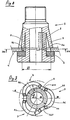
- FIGS. 1 and 2 show a valve 1 comprising a valve body 2 around which elastic elements 3 are disposed. These are, as known per se, shaped so as to be able to deform when a valve hole passes provided on the rim.
- the shape of the axially inner end 31 of said elastic elements is such that the radially inner face of said end 31 has, in the plane perpendicular to the axis of the valve, a curvature whose radius R (see FIG. 3) is more smaller than half the outside diameter D of the valve body.
- each elastic element 3 bears radially inwardly on the valve body 2 by two zones 310 located at the ends of the elastic elements 3. This support must take place at least in the final position (valve mounted).
- the shape of the valve 1 in the final position corresponds substantially to the initial shape of the valve.
- said axially inner end 31 of said elastic elements bear, in the final position, radially outward on the rim.
- said axially inner end 31 may comprise at least one protrusion 32 extending axially inward, and located radially, in the final position, valve mounted, between the valve body 2 and the rim 4.
- the protrusions 32 also make it possible to keep the valve 1 centered relative to the valve hole provided on the rim. If such protuberances 32 have not been provided, the centering will only be ensured by the deformation of the seal 5 resulting from its compression. This may sometimes be insufficient to keep the centering in service. In this case, it is preferable that said overall dimension "e" in the radial direction of the elastic elements, in the final position, is greater than the clearance formed by the difference between the diameter 0 of the valve hole and the diameter D of the body 2 of the valve 1. Thanks to this, even if the valve is offset so that the valve body 2 presses on the rim, the elastic element on the opposite side will not be able to slide towards the inside of the rim.
Landscapes
- Engineering & Computer Science (AREA)
- Mechanical Engineering (AREA)
- Check Valves (AREA)
- Portable Nailing Machines And Staplers (AREA)
- Tires In General (AREA)
Claims (6)
Priority Applications (1)
| Application Number | Priority Date | Filing Date | Title |
|---|---|---|---|
| AT87109680T ATE50207T1 (de) | 1986-07-24 | 1987-07-06 | Ventil fuer luftreifen ohne schlauch; befestigung des ventilsgehaeuses in der felge. |
Applications Claiming Priority (2)
| Application Number | Priority Date | Filing Date | Title |
|---|---|---|---|
| FR8610872 | 1986-07-24 | ||
| FR8610872A FR2601903B1 (fr) | 1986-07-24 | 1986-07-24 | Valve pour pneumatique sans chambre : fixation du corps de valve sur la jante. |
Publications (2)
| Publication Number | Publication Date |
|---|---|
| EP0254112A1 EP0254112A1 (de) | 1988-01-27 |
| EP0254112B1 true EP0254112B1 (de) | 1990-02-07 |
Family
ID=9337772
Family Applications (1)
| Application Number | Title | Priority Date | Filing Date |
|---|---|---|---|
| EP87109680A Expired - Lifetime EP0254112B1 (de) | 1986-07-24 | 1987-07-06 | Ventil für Luftreifen ohne Schlauch; Befestigung des Ventilsgehäuses in der Felge |
Country Status (9)
| Country | Link |
|---|---|
| US (1) | US4760860A (de) |
| EP (1) | EP0254112B1 (de) |
| JP (1) | JPS6334209A (de) |
| KR (1) | KR880001453A (de) |
| AT (1) | ATE50207T1 (de) |
| DE (1) | DE3761625D1 (de) |
| ES (1) | ES2013743B3 (de) |
| FR (1) | FR2601903B1 (de) |
| GR (1) | GR3000393T3 (de) |
Families Citing this family (8)
| Publication number | Priority date | Publication date | Assignee | Title |
|---|---|---|---|---|
| DE4420743C1 (de) * | 1994-06-15 | 1996-03-21 | Continental Ag | Hohem Überdruck ausgesetztes Ventil mit einem Ventilgehäuse |
| GB2340580A (en) * | 1998-08-15 | 2000-02-23 | Paul Brooke Sidebottom | Rim seal |
| US6347594B1 (en) * | 2000-01-28 | 2002-02-19 | Deere & Company | Narrow profile opener capable of high speed operation |
| KR100494060B1 (ko) * | 2002-06-04 | 2005-06-10 | (주)엠비아이 | 타이어 공기압 유지장치 |
| DE112008000165B4 (de) | 2007-01-24 | 2018-12-27 | Continental Automotive Gmbh | Reifendrucküberwachungssensor und Montageverfahren |
| US20080302425A1 (en) * | 2007-06-05 | 2008-12-11 | Continental Automotive Systems Us, Inc. | Formed Flange For Pressure Monitoring Valve Stem Mount |
| US8186287B2 (en) | 2009-11-19 | 2012-05-29 | Cnh Canada, Ltd. | Depth adjustment assembly for a disc opener of an agricultural implement |
| US8650945B2 (en) * | 2012-03-09 | 2014-02-18 | Nissan North America, Inc. | Retention member on valve stem sealing grommet |
Family Cites Families (9)
| Publication number | Priority date | Publication date | Assignee | Title |
|---|---|---|---|---|
| US2225472A (en) * | 1940-01-27 | 1940-12-17 | Albert W Franklin | Bushing |
| US2835305A (en) * | 1955-01-05 | 1958-05-20 | Dill Mfg Co | Tubeless tire valves for trucks and the like |
| US2998044A (en) * | 1958-10-06 | 1961-08-29 | Phillips Petroleum Co | Pneumatic tire |
| US3542109A (en) * | 1968-06-27 | 1970-11-24 | Scovill Manufacturing Co | Snap-in tire valve |
| GB1508216A (en) * | 1975-06-10 | 1978-04-19 | Ford Motor Co | Tyre valve |
| AU518285B2 (en) * | 1977-03-11 | 1981-09-24 | Michelin And Cie (Compagnie Generale Des Etablissements Michelin) | Inflation valve |
| FR2385548A1 (fr) * | 1977-03-30 | 1978-10-27 | Michelin & Cie | Valve pour pneumatique |
| DE7820058U1 (de) * | 1978-07-04 | 1978-10-12 | Bayerische Motoren Werke Ag, 8000 Muenchen | Ventil fuer einen fahrzeugreifen |
| US4411302A (en) * | 1981-09-28 | 1983-10-25 | Scovill Inc. | Snap-in tire valve |
-
1986
- 1986-07-24 FR FR8610872A patent/FR2601903B1/fr not_active Expired
-
1987
- 1987-07-06 EP EP87109680A patent/EP0254112B1/de not_active Expired - Lifetime
- 1987-07-06 ES ES87109680T patent/ES2013743B3/es not_active Expired - Lifetime
- 1987-07-06 DE DE8787109680T patent/DE3761625D1/de not_active Expired - Fee Related
- 1987-07-06 AT AT87109680T patent/ATE50207T1/de not_active IP Right Cessation
- 1987-07-09 US US07/071,480 patent/US4760860A/en not_active Expired - Fee Related
- 1987-07-23 JP JP62184658A patent/JPS6334209A/ja active Pending
- 1987-07-24 KR KR1019870008063A patent/KR880001453A/ko not_active Application Discontinuation
-
1990
- 1990-03-21 GR GR90400156T patent/GR3000393T3/el unknown
Also Published As
| Publication number | Publication date |
|---|---|
| FR2601903B1 (fr) | 1988-11-10 |
| EP0254112A1 (de) | 1988-01-27 |
| US4760860A (en) | 1988-08-02 |
| FR2601903A1 (fr) | 1988-01-29 |
| ES2013743B3 (es) | 1990-06-01 |
| ATE50207T1 (de) | 1990-02-15 |
| DE3761625D1 (de) | 1990-03-15 |
| JPS6334209A (ja) | 1988-02-13 |
| KR880001453A (ko) | 1988-04-23 |
| GR3000393T3 (en) | 1991-06-07 |
Similar Documents
| Publication | Publication Date | Title |
|---|---|---|
| EP0122848B2 (de) | Verfahren zum Herstellen einer hydraulischen Verbindung | |
| EP0647789B1 (de) | Differential-Gehäuse | |
| WO1996014526A1 (fr) | Embrayage de verrouillage pour dispositif d'accouplement hydrocinetique, notamment pour vehicules automobiles et son procede de montage | |
| EP0187079A1 (de) | Dübel, der durch einen Konus aufgespreizt wird | |
| EP0254112B1 (de) | Ventil für Luftreifen ohne Schlauch; Befestigung des Ventilsgehäuses in der Felge | |
| WO2002050442A1 (fr) | Soufflet d'etancheite, joint de transmission equipe d'un tel soufflet et procede de fixation d'un tel soufflet | |
| CH624890A5 (de) | ||
| FR3015951A1 (fr) | Jante de roue d'aeronef a talon amovible. | |
| FR2698823A1 (fr) | Dispositif d'anneau perfectionné pour roulage à plat. | |
| EP0848175B1 (de) | Feste Kupplungseinrichtung für zwei Wellen | |
| EP0460989B1 (de) | Schlauchbinder mit Reservekapazität | |
| FR2622871A1 (fr) | Bouchon amovible de fermeture etanche d'un orifice et son utilisation comme bouchon de vidange d'un carter d'huile | |
| FR2606476A1 (fr) | Embrayage a friction a element de progressivite | |
| WO2015040296A1 (fr) | Disque de frein d'un véhicule automobile | |
| EP0770789A1 (de) | Hydraulische Kupplungsbetätigungsvorrichtung | |
| LU84588A1 (fr) | Frein a couronne fixee a la roue | |
| EP2763858B1 (de) | Fahrzeugrad mit einer abdeckung und entsprechende abdeckung | |
| FR2743132A1 (fr) | Piece souple susceptible d'etre montee dans une ouverture | |
| FR2843562A1 (fr) | Valve de gonflage d'un pneumatique munie d'un capteur electronique de la pression de gonflage | |
| FR2652623A1 (fr) | Dispositif de butee d'embrayage a autocentrage du type tiree. | |
| FR2642137A3 (fr) | Raccord pour allonges pour valves de gonflage de pneus de vehicules automobiles | |
| FR2690959A1 (fr) | Friction d'embrayage, notamment pour véhicule automobile. | |
| EP0736146B1 (de) | Kupplungsausrücklager | |
| EP0192939A1 (de) | Felgenband | |
| EP0345612B1 (de) | Radfelge für Reifen mit umschlingender Einklammerung |
Legal Events
| Date | Code | Title | Description |
|---|---|---|---|
| PUAI | Public reference made under article 153(3) epc to a published international application that has entered the european phase |
Free format text: ORIGINAL CODE: 0009012 |
|
| 17P | Request for examination filed |
Effective date: 19870706 |
|
| AK | Designated contracting states |
Kind code of ref document: A1 Designated state(s): AT BE CH DE ES FR GB GR IT LI LU NL SE |
|
| 17Q | First examination report despatched |
Effective date: 19881028 |
|
| GRAA | (expected) grant |
Free format text: ORIGINAL CODE: 0009210 |
|
| AK | Designated contracting states |
Kind code of ref document: B1 Designated state(s): AT BE CH DE ES FR GB GR IT LI LU NL SE |
|
| REF | Corresponds to: |
Ref document number: 50207 Country of ref document: AT Date of ref document: 19900215 Kind code of ref document: T |
|
| ITF | It: translation for a ep patent filed |
Owner name: JACOBACCI & PERANI S.P.A. |
|
| REF | Corresponds to: |
Ref document number: 3761625 Country of ref document: DE Date of ref document: 19900315 |
|
| GBT | Gb: translation of ep patent filed (gb section 77(6)(a)/1977) | ||
| REG | Reference to a national code |
Ref country code: GR Ref legal event code: FG4A Free format text: 3000393 |
|
| PLBE | No opposition filed within time limit |
Free format text: ORIGINAL CODE: 0009261 |
|
| STAA | Information on the status of an ep patent application or granted ep patent |
Free format text: STATUS: NO OPPOSITION FILED WITHIN TIME LIMIT |
|
| 26N | No opposition filed | ||
| ITTA | It: last paid annual fee | ||
| PGFP | Annual fee paid to national office [announced via postgrant information from national office to epo] |
Ref country code: GR Payment date: 19940516 Year of fee payment: 8 |
|
| PGFP | Annual fee paid to national office [announced via postgrant information from national office to epo] |
Ref country code: CH Payment date: 19940527 Year of fee payment: 8 |
|
| PGFP | Annual fee paid to national office [announced via postgrant information from national office to epo] |
Ref country code: SE Payment date: 19940617 Year of fee payment: 8 Ref country code: DE Payment date: 19940617 Year of fee payment: 8 |
|
| PGFP | Annual fee paid to national office [announced via postgrant information from national office to epo] |
Ref country code: BE Payment date: 19940620 Year of fee payment: 8 |
|
| PGFP | Annual fee paid to national office [announced via postgrant information from national office to epo] |
Ref country code: GB Payment date: 19940628 Year of fee payment: 8 |
|
| PGFP | Annual fee paid to national office [announced via postgrant information from national office to epo] |
Ref country code: LU Payment date: 19940630 Year of fee payment: 8 |
|
| EPTA | Lu: last paid annual fee | ||
| PGFP | Annual fee paid to national office [announced via postgrant information from national office to epo] |
Ref country code: NL Payment date: 19940731 Year of fee payment: 8 |
|
| EAL | Se: european patent in force in sweden |
Ref document number: 87109680.6 |
|
| PG25 | Lapsed in a contracting state [announced via postgrant information from national office to epo] |
Ref country code: LU Free format text: LAPSE BECAUSE OF NON-PAYMENT OF DUE FEES Effective date: 19950706 Ref country code: GB Effective date: 19950706 |
|
| PG25 | Lapsed in a contracting state [announced via postgrant information from national office to epo] |
Ref country code: SE Effective date: 19950707 |
|
| PGFP | Annual fee paid to national office [announced via postgrant information from national office to epo] |
Ref country code: ES Payment date: 19950707 Year of fee payment: 9 |
|
| PGFP | Annual fee paid to national office [announced via postgrant information from national office to epo] |
Ref country code: FR Payment date: 19950710 Year of fee payment: 9 |
|
| PGFP | Annual fee paid to national office [announced via postgrant information from national office to epo] |
Ref country code: AT Payment date: 19950720 Year of fee payment: 9 |
|
| PG25 | Lapsed in a contracting state [announced via postgrant information from national office to epo] |
Ref country code: LI Effective date: 19950731 Ref country code: CH Effective date: 19950731 Ref country code: BE Effective date: 19950731 |
|
| BERE | Be: lapsed |
Owner name: MICHELIN & CIE (CIE GENERALE DES ETS MICHELIN) Effective date: 19950731 |
|
| PG25 | Lapsed in a contracting state [announced via postgrant information from national office to epo] |
Ref country code: GR Free format text: THE PATENT HAS BEEN ANNULLED BY A DECISION OF A NATIONAL AUTHORITY Effective date: 19960131 |
|
| PG25 | Lapsed in a contracting state [announced via postgrant information from national office to epo] |
Ref country code: NL Effective date: 19960201 |
|
| GBPC | Gb: european patent ceased through non-payment of renewal fee |
Effective date: 19950706 |
|
| REG | Reference to a national code |
Ref country code: CH Ref legal event code: PL |
|
| REG | Reference to a national code |
Ref country code: GR Ref legal event code: MM2A Free format text: 3000393 |
|
| NLV4 | Nl: lapsed or anulled due to non-payment of the annual fee |
Effective date: 19960201 |
|
| PG25 | Lapsed in a contracting state [announced via postgrant information from national office to epo] |
Ref country code: DE Effective date: 19960402 |
|
| EUG | Se: european patent has lapsed |
Ref document number: 87109680.6 |
|
| PG25 | Lapsed in a contracting state [announced via postgrant information from national office to epo] |
Ref country code: AT Effective date: 19960706 |
|
| PG25 | Lapsed in a contracting state [announced via postgrant information from national office to epo] |
Ref country code: ES Free format text: LAPSE BECAUSE OF THE APPLICANT RENOUNCES Effective date: 19960708 |
|
| PG25 | Lapsed in a contracting state [announced via postgrant information from national office to epo] |
Ref country code: FR Effective date: 19970328 |
|
| REG | Reference to a national code |
Ref country code: FR Ref legal event code: ST |
|
| REG | Reference to a national code |
Ref country code: ES Ref legal event code: FD2A Effective date: 19991102 |
|
| PG25 | Lapsed in a contracting state [announced via postgrant information from national office to epo] |
Ref country code: IT Free format text: LAPSE BECAUSE OF NON-PAYMENT OF DUE FEES;WARNING: LAPSES OF ITALIAN PATENTS WITH EFFECTIVE DATE BEFORE 2007 MAY HAVE OCCURRED AT ANY TIME BEFORE 2007. THE CORRECT EFFECTIVE DATE MAY BE DIFFERENT FROM THE ONE RECORDED. Effective date: 20050706 |