EP0253784A1 - Automatische Vorrichtung für das Ein- beziehungsweise Aussetzen eines Farbkorbes - Google Patents
Automatische Vorrichtung für das Ein- beziehungsweise Aussetzen eines Farbkorbes Download PDFInfo
- Publication number
- EP0253784A1 EP0253784A1 EP87830281A EP87830281A EP0253784A1 EP 0253784 A1 EP0253784 A1 EP 0253784A1 EP 87830281 A EP87830281 A EP 87830281A EP 87830281 A EP87830281 A EP 87830281A EP 0253784 A1 EP0253784 A1 EP 0253784A1
- Authority
- EP
- European Patent Office
- Prior art keywords
- jaws
- head
- lifting
- closing
- casing
- Prior art date
- Legal status (The legal status is an assumption and is not a legal conclusion. Google has not performed a legal analysis and makes no representation as to the accuracy of the status listed.)
- Withdrawn
Links
- 238000004043 dyeing Methods 0.000 title claims abstract description 9
- 239000000463 material Substances 0.000 claims abstract description 9
- 239000004753 textile Substances 0.000 claims abstract description 7
- 235000001674 Agaricus brunnescens Nutrition 0.000 claims abstract description 6
- 230000011664 signaling Effects 0.000 claims abstract description 4
- 239000007787 solid Substances 0.000 claims description 4
- 238000006073 displacement reaction Methods 0.000 claims description 3
- 230000008878 coupling Effects 0.000 claims description 2
- 238000010168 coupling process Methods 0.000 claims description 2
- 238000005859 coupling reaction Methods 0.000 claims description 2
- 230000000284 resting effect Effects 0.000 claims description 2
- 238000007493 shaping process Methods 0.000 claims 2
- 230000033001 locomotion Effects 0.000 description 4
- 238000012790 confirmation Methods 0.000 description 1
- 230000001788 irregular Effects 0.000 description 1
- 230000000149 penetrating effect Effects 0.000 description 1
Images

Classifications
-
- D—TEXTILES; PAPER
- D06—TREATMENT OF TEXTILES OR THE LIKE; LAUNDERING; FLEXIBLE MATERIALS NOT OTHERWISE PROVIDED FOR
- D06B—TREATING TEXTILE MATERIALS USING LIQUIDS, GASES OR VAPOURS
- D06B5/00—Forcing liquids, gases or vapours through textile materials to effect treatment, e.g. washing, dyeing, bleaching, sizing impregnating
- D06B5/12—Forcing liquids, gases or vapours through textile materials to effect treatment, e.g. washing, dyeing, bleaching, sizing impregnating through materials of definite length
- D06B5/14—Forcing liquids, gases or vapours through textile materials to effect treatment, e.g. washing, dyeing, bleaching, sizing impregnating through materials of definite length through fibres, slivers or rovings
Definitions
- the invention relates to an automated apparatus for the hooking and unhooking, that is release of the end of the central rod of a special container or "basket” containing textile material (like reels of textile rove), said basket being lifted to be placed in a tank for a dyeing plant, or to be withdrawn therefrom after the material is dyed.
- an automated apparatus for the hooking and release of the central rod end of a "basket” containing textile material to be lifted and transferred into a dyeing tank, said end having a shank with an overhanging mushroom head comprises in combination: a casing to which means are anchored for the lifting and the lowering of the apparatus; a pair of opposite jaws articulated at and inside the casing, able to engage, in a closing position, the edge of the mushroom head which projects from the shank, for the hooking and the lifting, and to guide, in the opening position, the entry in vertical direction of the head into the apparatus, as well as means for signalling the just occurred entry of said head beyond said jaws for the consensus to the closing thereof; as well as means to cause the jaws rotation from the opening position to the closing position, with associated means for signalling the just occurred closing for the lifting and the just occurred opening for the release of the basket; the lifting, lowering and displacements of the apparatus, as well as the means for the closing and opening of the jaws being co-ordinated and controlled by
- the casing of the apparatus is pivotally secured to lifting members and to guide members.
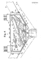
- the apparatus 1 is provided for the lifting, in a fully automated manner, of dyeing "baskets" 3, each having a central rod 5, with a shank 7 and a head 9, in order to be lifted by two jaws which seize the head 9.
- the basket 3 is symmetrical and lacking in side holds, and therefore the lifting thereof is provided by seizing said central rod 7, 9.
- the outline of the basket - which appears as a revolution solid - has a recess that is a free space 11 in the center of its top part, from which recess, shaped approximately like an obtuse angle, the shank 7 with the head 9 projects upwards, said shank and head being anyway inside said outline.
- the apparatus 1 exhibits transversally a corresponding configuration consisting of an isosceles trapezoid with its minor base in lower position, with a superimposed rectangle, which configuration allows said apparatus to be lowered as much as possible into the recess 11 to "seize" the head 9.
- Said apparatus comprises thus a substantially prismatic casing 13 (the prism base being the described irregular polygon formed by the isosceles trapezoid with the major base in common with the superimposed rectangle), on the vertical sides 13V of which casing, shaped wings 15 are fixed for the connection of the apparatus with telescopic rods 17, 18 sliding within tubular guides 19; the tubular guides 19 are long enough to guide the lowering of the apparatus until it reaches the top of the basket to be lifted.
- the coupling of wings 15 with the rods length 18 is obtained by bushes 16.
- a pair of connecting spiral springs 21 allows limited angular displacements of said length 18 - which is not guided - of rods, and thus limited inclinations of the apparatus 1 so that the head 9 of shank 7 of the basket 3 is able to penetrate inside the casing 13 even in case of faulty centering of the apparatus relative to the basket.
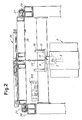
- the lowering and the lifting of the apparatus 1 are achieved by means of a pair of chains 23, secured to the casing 13, simultaneously operated by a cylinder-piston system 25 (Fig. 2) mounted on a carriage 26, which carriage is able to move on their wheels 27 in the two directions of arrow f26 (Fig. 1) along rails 28 for the apparatus movements - according to a determined alignment - in order to pick up or lay down a basket.
- the apparatus 1 must operate in a fully automated manner, according to a predetermined working program that can be stored in a suitable programmer generally indicated by 100 in Fig. 2; in order to cooperate with the programmer, the apparatus is characteristically provided with interlocking and consensus means able to avoid any incorrect handling that would make the operation unreliable.
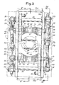
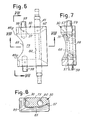
- limit-switches are used in the form of proximity switches, more exactly, with the lowering of the apparatus 1 into the recess 11 the head 9 penetrates within a lower cleft, that is opening, of the casing 13, which is located between the edges of the head walls 13V and the cross walls 13F of same casing, by going through the inside of two jaws being mirror-like equal and opposite to each other, shaped with suitable cavities, which jaws are shown in their vertical opening position in Figs. 7 and 8 and in short dashes line in Fig. 4.
- the head 9 By penetrating between the lifted jaws 30 the head 9 causes the lifting of pegs 29 projecting inwardly from the respective ends of shaped levers 31 which, as a consequence, rotate in the direction of arrows f31 thus causing the rotation of shafts 33 which are solid with bushes 35 located beyond the front wall 13F of the casing.
- the bushes 35 have radial short rods 37 which, because of said rotation, influence limit switches 39 that deliver an electrical signal communicating to the programming member 100 that the apparatus is correctly placed in lowered position wherein the basket head 9 can be "seized".
- the cylinder-piston system 25 stops and the lowering of the apparatus does not go on.
- the cylinder-piston system has usually a limit switch (not shown) mounted thereon, which provides a further signal indicating that the apparatus lowering - which is also programmed - has been completed.
- the programmer thus receives a first signal and a confirmation signal, after the reception of which signals - constituting a double safety means - it gives consent for the closing of the jaws 30.
- Each jaw 30 is predisposed for rotating solid with a shaft 41 on which, externally of the walls 13F of the casing, a crank 43 is keyed on one side, and a bush 45 is keyed on the opposite side.
- the rod 49A of a cylinder-piston system 49 is articulated through a ball joint 47.
- the cylinder-piston system 49 can oscillate inasmuch as the end of the cylinder on the opposite side of the rod 49A is articulated at 50.
- the cylinder-piston system 49,49 is driven so that the rod 49A moves back inside the cylinder and drives into rotation the corresponding crank 43 towards the center of the apparatus, that is, towards the Y-Y axis.
- each jaw 30 rotates until it finds itself, so to say, "knocked down" - and coplanar with the other jaw - in the closing position of Fig.
- a short rod 51 projects radially from each bush 45 and, on the end of rotation of the corresponding jaw, influences a limit switch 53 which delivers an electrical signal of "closed jaws" to the programmer.
- the rod 51 Prior to the start of the jaws closing motion, the rod 51 found itself to influenece a limit switch 55, which had delivered and was maintaining - until that moment - a signal of open jaws for the consent of the apparatus lowering.
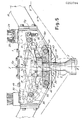
- Each jaw 30 has two stout laterally projecting cylindrical studs 59 blocked by pins 56 within dead holes 57.
- the studs 59 upon the rotation of each jaw from the upright position (open jaws) to the "knocked down" position (jaws closed), slide along curved slots or buttonholes 61 - having arc-like development - formed on each of the walls 13F of casing 13.
- the slots 61 have, at their ends, seats 63E and 63A for correctly accomodating the studs 59 therein at the ends of their run.
- the jaws 30, substantially of parallelepiped form, are variously shaped and have an almost cylindrical front cavity 65 (oriented towards the Y-Y axis) which extends downwardly with an invitation frustum conical or flared portion 67.
- the head 9 is guided, upon its entry inside the apparatus, by said portions 67 of frustum conical surface.
- the jaws 30 On top the jaws 30 have a recess 69 intended to "surround" the shank 7 when they find themselves in knocked down, that is, closing position.
- the recess 69 is arc-shaped and has bends or fillets 69R of opposite curvature.
- each of jaws 30 have a through hole 60 for the passage of the shaft 41 dowelled in 62 and supported by bushings or the like housed within holes of both the opposite walls 13F.
- the back 73 of jaws 30 is flat to provide a correct support for head 9.
- the chains 23 are driven into a downwards movement by the cylinder-piston system 25 until they complete a programmed run, so that the head 9 - which had been resting down on the back 73 of jaws 30 - raises up again inside the apparatus 1 pushing upwards again pegs 29 and thus putting into rotation levers 31. Also bushes 35 rotate again and, therefore, the rods 37 influence the limit switches 39 which deliver a signal which, this time, is of consent (in such a way being interpreted by the programmer) to the opening of jaws 30.
- the apparatus according to the invention is able to provide, in a self-contained manner, for all the movements necessary to withdraw the filled baskets and to place them into the respective dyeing tanks and, subsequently, to withdraw them from the tanks and place them again at locations where they are emptied by taking the dyed material out of them and are once again filled with material to be dyed.
- Figs. 1 and 2 show the carriage 26 (and then the apparatus 1) being possibly moved only in the two directions of arrow f26. It is apparent, however, that the rails 28 - on which the wheels 27 move - are able, in turn, to be supported by a further carriage (a bridge crane, for example) being movable into the two directions orthogonal to the direction indicated by arrow f26.
- a further carriage a bridge crane, for example
Landscapes
- Engineering & Computer Science (AREA)
- Chemical & Material Sciences (AREA)
- Materials Engineering (AREA)
- Textile Engineering (AREA)
- Treatment Of Fiber Materials (AREA)
Applications Claiming Priority (2)
| Application Number | Priority Date | Filing Date | Title |
|---|---|---|---|
| IT8609444A IT1216239B (it) | 1986-07-18 | 1986-07-18 | Attrezzatura automatica di agganciamento e sganciamento della asta centrale di un cesto per tintoria per il sollevamento didetto cesto. |
| IT944486 | 1986-07-18 |
Publications (1)
| Publication Number | Publication Date |
|---|---|
| EP0253784A1 true EP0253784A1 (de) | 1988-01-20 |
Family
ID=11130237
Family Applications (1)
| Application Number | Title | Priority Date | Filing Date |
|---|---|---|---|
| EP87830281A Withdrawn EP0253784A1 (de) | 1986-07-18 | 1987-07-17 | Automatische Vorrichtung für das Ein- beziehungsweise Aussetzen eines Farbkorbes |
Country Status (3)
| Country | Link |
|---|---|
| EP (1) | EP0253784A1 (de) |
| JP (1) | JPS6385157A (de) |
| IT (1) | IT1216239B (de) |
Citations (4)
| Publication number | Priority date | Publication date | Assignee | Title |
|---|---|---|---|---|
| FR1132578A (fr) * | 1955-06-20 | 1957-03-13 | Perfectionnements aux machines effectuant les opérations de lavage, nettoyage, brassage, rinçage, essorage, teinture, etc. | |
| DE1095244B (de) * | 1958-10-21 | 1960-12-22 | Walther Klatt | Pack- und Einpressvorrichtung fuer das Faerben von losem Fasergut |
| GB2023679A (en) * | 1978-06-24 | 1980-01-03 | Bottomley & Sons Ltd E | Compacting fibrous stock in a dye basket |
| US4455931A (en) * | 1982-09-30 | 1984-06-26 | Gaston County Dyeing Machine Company | Apparatus and method for processing raw fiber stock |
-
1986
- 1986-07-18 IT IT8609444A patent/IT1216239B/it active
-
1987
- 1987-07-17 JP JP62177353A patent/JPS6385157A/ja active Pending
- 1987-07-17 EP EP87830281A patent/EP0253784A1/de not_active Withdrawn
Patent Citations (4)
| Publication number | Priority date | Publication date | Assignee | Title |
|---|---|---|---|---|
| FR1132578A (fr) * | 1955-06-20 | 1957-03-13 | Perfectionnements aux machines effectuant les opérations de lavage, nettoyage, brassage, rinçage, essorage, teinture, etc. | |
| DE1095244B (de) * | 1958-10-21 | 1960-12-22 | Walther Klatt | Pack- und Einpressvorrichtung fuer das Faerben von losem Fasergut |
| GB2023679A (en) * | 1978-06-24 | 1980-01-03 | Bottomley & Sons Ltd E | Compacting fibrous stock in a dye basket |
| US4455931A (en) * | 1982-09-30 | 1984-06-26 | Gaston County Dyeing Machine Company | Apparatus and method for processing raw fiber stock |
Also Published As
| Publication number | Publication date |
|---|---|
| JPS6385157A (ja) | 1988-04-15 |
| IT8609444A0 (it) | 1986-07-18 |
| IT1216239B (it) | 1990-02-22 |
Similar Documents
| Publication | Publication Date | Title |
|---|---|---|
| US4791705A (en) | Machine for meat treatment and maceration, with automatic loading and unloading | |
| PT1795467E (pt) | Sistema de transferência de contentores entre o navio e o armazém | |
| EP2709917B1 (de) | Vorrichtung und verfahren zur automatischen öffnung von kisten für landwirtschaftliche produkte | |
| EP0253784A1 (de) | Automatische Vorrichtung für das Ein- beziehungsweise Aussetzen eines Farbkorbes | |
| US5979961A (en) | Tube bundle lifting device | |
| US5472503A (en) | Vertical load transferring apparatus | |
| US3040921A (en) | Plate handling apparatus | |
| US3845794A (en) | Filling systems | |
| US3558178A (en) | Hydraulic rail lifter | |
| ITTO970539A1 (it) | Attrezzatura di manovra per aste usate negli impianti di trivellazione | |
| NO302350B1 (no) | Forbindelsesstykke for feste av en fortöyning i en strekkforankringsplattform til sjöbunnen | |
| CN217124793U (zh) | 一种悬挂式列车用集装箱转锁系统 | |
| NO333446B1 (no) | Anordning for automatisk til- og frakobling av last ved kranloft | |
| PL79181B1 (de) | ||
| EP1423317B1 (de) | Maschine zum orientieren und ausrichten von behältern oder flaschen aus kuststoff | |
| EP0384507A1 (de) | Vorrichtung zum Abreissen von Pfählen | |
| RU2219605C2 (ru) | Способ разделки двухпучковой топливной сборки ядерного реактора для её последующего хранения и камера разделки для осуществления способа | |
| SU1049367A1 (ru) | Устройство дл переноса тары | |
| EP0133422A2 (de) | Automatischer Apparat zur Behandlung und zum Umschnüren von Packungen (Faden) von Textilfaserbändern | |
| DK159545B (da) | Apparat til at gribe om og loefte fyldte saekke | |
| GB2102854A (en) | Charging a stranding machine | |
| SU1664720A1 (ru) | Захват-кантователь дл контейнеров с цапфами | |
| SU1402639A1 (ru) | Швартовное устройство камеры шлюза | |
| US5478056A (en) | Support for foundry ladels for a continuous casting | |
| CN120922488B (zh) | 一种船用集装箱弃箱装置及其操作方法 |
Legal Events
| Date | Code | Title | Description |
|---|---|---|---|
| PUAI | Public reference made under article 153(3) epc to a published international application that has entered the european phase |
Free format text: ORIGINAL CODE: 0009012 |
|
| AK | Designated contracting states |
Kind code of ref document: A1 Designated state(s): AT BE CH DE ES FR GB GR LI LU NL SE |
|
| STAA | Information on the status of an ep patent application or granted ep patent |
Free format text: STATUS: THE APPLICATION IS DEEMED TO BE WITHDRAWN |
|
| 18D | Application deemed to be withdrawn |
Effective date: 19880721 |
|
| RIN1 | Information on inventor provided before grant (corrected) |
Inventor name: GUALCHIERANI, SERGIO |