EP0253388A1 - Dispositif de réglage de conduites d'arrosage de champs - Google Patents
Dispositif de réglage de conduites d'arrosage de champs Download PDFInfo
- Publication number
- EP0253388A1 EP0253388A1 EP87110288A EP87110288A EP0253388A1 EP 0253388 A1 EP0253388 A1 EP 0253388A1 EP 87110288 A EP87110288 A EP 87110288A EP 87110288 A EP87110288 A EP 87110288A EP 0253388 A1 EP0253388 A1 EP 0253388A1
- Authority
- EP
- European Patent Office
- Prior art keywords
- housing
- filter
- segments
- valve
- longitudinal
- Prior art date
- Legal status (The legal status is an assumption and is not a legal conclusion. Google has not performed a legal analysis and makes no representation as to the accuracy of the status listed.)
- Granted
Links
Images

Classifications
-
- A—HUMAN NECESSITIES
- A01—AGRICULTURE; FORESTRY; ANIMAL HUSBANDRY; HUNTING; TRAPPING; FISHING
- A01G—HORTICULTURE; CULTIVATION OF VEGETABLES, FLOWERS, RICE, FRUIT, VINES, HOPS OR SEAWEED; FORESTRY; WATERING
- A01G25/00—Watering gardens, fields, sports grounds or the like
- A01G25/16—Control of watering
- A01G25/162—Sequential operation
Definitions
- the invention relates to an adjustment valve for controlling the supply of liquid to a field spray line comprising a plurality of line sections, which has a filter for the liquid and a valve housing with a plurality of housing segments, each of which has a so-called section valve for switching a line section of the field spray line on and off,
- the valve housing forms an inlet longitudinal channel extending from an inlet opening of the latter through the housing segments and a longitudinal return channel which likewise extends through the housing segments and leads to a return opening of the housing and, furthermore, in each housing segment the longitudinal inlet channel through the section valve optionally with an outlet opening of the housing segment which can be connected to the field spray line or can be connected to the return longitudinal channel.
- a filter housing which can be removed, is arranged between a first assembly with a pressure adjustment valve and an overall shut-off valve and a distribution device, which comprises the valve housing with the section valves .
- the pressure filter has the shape of a sieve cylinder, which is arranged upright in the filter housing and can be removed from it downwards after a bottom closure part of the filter housing has been unscrewed.
- This bottom closure part carries a ball valve with an outlet connection, which is used for quick cleaning of the sieve cylinder, for which the ball valve is opened and the sieve cylinder is rinsed in the longitudinal direction - during operation, the liquid flows into the sieve cylinder in the axial direction and flows through it in the radial direction from the inside Outside.
- field spray lines are usually composed of several line sections, the number of which depends on the application, but in the known adjustment fitting described, the screen cylinder and filter housing are always the same size, in the prior art the effective screen area per line section of the field spray line depends on the number of these line sections and is e.g. with three line sections approx. 2,400 mm2, with five line sections approx. 1,450 mm2 and with seven line sections approx. 1,050 mm2 per field spray line section.
- the invention was based on the object of improving the known setting valve in such a way that it can not only be produced more cheaply, but can also be adapted to the length of the field spray line with regard to the effective screen area of the pressure filter. According to the invention, this is accomplished in that the filter is designed as a sieve cylinder which can be inserted into the longitudinal inlet channel of the section valve housing and in its longitudinal direction from the Filter segments assigned to housing segments is composed.
- the cavity formed by the longitudinal inlet channel is used as a receiving space for the screen cylinder, so that a separate filter housing can be saved, and moreover, the length of the screen cylinder and thus the effective screen area can be adapted to the length of the field spray line by a more or less large number of filter segments is assembled to a sieve cylinder.
- the filter segments are of identical design, as a result of which the production costs can be reduced even further.
- the length of the filter elements equal to the length of the associated housing segment and, in particular, to design all filter elements, as well as all housing segments, to be of the same length, although it would be conceivable in principle that the one housing to build segment-assigned screen cylinder section from several filter elements or to allow a filter element to extend over several housing segments.
- the filter In order to be able to remove and install the filter as quickly and easily as possible, it is recommended to provide the filter with a connector located in the inlet opening, which is detachably and sealedly arranged in the valve housing by means of a securing element and a seal.
- the connector could be molded onto a special filter segment, but in order to have to produce only a single type of filter segment, in a preferred embodiment the connector can be locked in the same way as a filter segment with the first filter segment of the screen cylinder.
- the securing element could also be a locking element;
- a securing element in the form of a hairpin-shaped clip is preferred, the legs of which can be inserted from the outside into transverse bores of the valve housing and into an outer circumferential groove of the filter, the transverse bores and the circumferential groove expediently lying in front of an O-ring that seals the seal between the connector and the Valve housing takes over, so that the valve housing cannot leak at the mentioned cross holes.
- the housing segments have a control window for visual inspection of the degree of contamination of the filter. If the control window is closed by a transparent, preferably screwed plug If the opening is formed, a further advantage can also be achieved with a corresponding arrangement of the control window, namely that the assembly of parts held in the housing segment can be carried out more easily or is possible in the first place - it does not matter at which point - in longitudinal and Circumferential direction of the screen cylinder - the filter is viewed in a housing segment, so that the position of the control window can be optimally selected with regard to the ease of assembly of parts.
- the invention thus created an adjustment valve which was inexpensive to manufacture and which, for example, also enables the user to adapt the adjustment fitting to an enlarged field spray line by purchasing valve housing and filter segments.
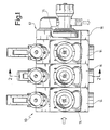
- valve housing 12 which is composed of a plurality of housing segments 14 and two housing end segments, of which only the housing end segment 16 has been drawn.
- the various segments of the valve housing 12 are held together, for example, by tie rods, not shown, designed as screws.
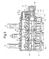
- the frontal sealing of the housing segments 14 and 16 against each other serves O-rings 18 and 20, which result from FIG. 3.
- the housing segments 14 with through openings form an inlet longitudinal channel 22 through which the spray or spray liquid flows in the direction of the arrow A shown in FIG. 3.
- Second through openings in the housing segments 14 together form a return longitudinal channel 24, which runs parallel to the longitudinal inlet channel 22.
- a so-called section valve 26 and a constant pressure throttle 28 are installed in each of the housing segments 14.
- the inlet longitudinal channel 22 can be connected either to an outlet opening 30 of the relevant housing segment 14 or to the return longitudinal channel 24.
- the outlet opening 30 is then connected via a hose or the like to the line section of a field spray line belonging to the relevant housing segment 14.
- the section valve 26 has a quick-release lever 34 which can be pivoted about an axis 32 and by means of which a valve shaft 36 can be moved back and forth in the direction of the double arrow B.
- a valve disk 38 is fastened to this valve stem, which cooperates with an upper and a lower valve seat 40 and 42, respectively.
- the valve disk 38 releases a passage 44 formed in the housing segment 14 from the inlet longitudinal channel 22 to the outlet opening 30, while the inlet longitudinal channel 22 is connected to the return longitudinal channel 24 via a passage 46 when the valve disk 38 is placed against the lower valve seat 42, which is done by pivoting the quick-release lever 34 into the closed position shown in broken lines in FIG. 2.
- the constant pressure throttle 28, which can be adjusted with the aid of a rotary handle 50, serves to form a throttle adjustable cross section between the inlet longitudinal channel 22 and the return longitudinal channel 24, in order to make the pressure drop per housing segment 14 along the inlet longitudinal channel 22 independent thereof whether the section valve 26 now opens the passage 44 to the outlet opening 30 or the passage 46 to the return longitudinal channel 24.
- a cleaning valve 54 is installed in the housing end segment 16, which has an inflow channel 56 aligned with the inlet longitudinal channel 22 and an outlet connection 58, between which there is a valve seat 60 in the housing of the cleaning valve, which valve valve cooperates with a valve member 62 which can be adjusted in the axial direction by means of a turning handle 66 held by a thread 64, around a passage to open more or less between the inlet channel 56 and the outlet port 58.
- a pipe bend 70 connects the outlet connector 58 to the return longitudinal channel 24, but when the cleaning valve 54 is rotated through 180 ° about the longitudinal axis of the longitudinal inlet channel 22, the outlet connector 58 can also form an outlet connector.
- a hairpin-shaped clip 74 serves to hold the cleaning valve 54 in the housing end segment 16.
- This bracket is inserted with its two legs into bores of the housing end segment 16, which run transversely to the longitudinal direction of the channels 22 and 24, and a circumferential groove 76 of the cleaning valve 54 (not shown in any more detail) and thus holds the latter to the housing end segment 16.
- the sealing of the cleaning valve 54 in the housing end segment 16 is served by an O-ring 78 which lies within the bracket 74 and thus prevents leakage at the above-mentioned cross bores.
- the inlet longitudinal channel 22 receives a sieve cylinder, designated as a whole as 80, which sealingly abuts the cleaning valve 54.
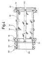
- the screen cylinder 80 is composed of as many filter segments 82 as the valve housing 12 has housing segments 14, and FIG. 4 shows such a filter segment 82 in detail.
- the filter segments 82 are one-piece plastic injection molded parts with two end rings 84 and 86 at the ends, which are formed by longitudinal ribs 88 are integrally connected. These longitudinal ribs carry the actual cylindrical sieve 90, which is supported in the radial direction outwards by integrally formed reinforcing rings 92.
- the end rings 84 and 86 are provided with complementarily designed latching elements 94 and 96, which advantageously have the shape of molded short sockets so as to be able to bring about a rigid connection between the filter segments 82.
- the nozzle-shaped locking elements 94 and 96 have a plurality of slots 100 on their circumference.
- connection piece 102 shown in FIG. 4 which has a circumferential groove 104 in order to be held by means of a clamp 74 in the same way on a housing end segment, not shown, as is the case with the cleaning valve 54 Case is.
- an O-ring (not shown) on the connector 102 also serves as a seal, as has been described with reference to the cleaning valve 54.
- the distribution device 10 now allows the sieve cylinder 80 to be rinsed by opening the cleaning valve 54 in order to flush the deposited dirt into the return longitudinal channel 24 or, if the outlet connection 58 is not connected to the return longitudinal channel 24, to allow the dirt to be flushed out into the open.
- the distribution device 10 allows a visual inspection of the screen cylinder 80.
- an opening 110 is formed in each of the housing segments 14, which can be closed in a pressure-tight manner by means of a stopper 112, the stopper being able to be held with a clamp 74 in the same way as this is the case with the cleaning valve 54.
- the axis of the opening 110 is directed towards the longitudinal axis of the longitudinal inlet channel 22, so that the sieve cylinder can be checked for the degree of its contamination through the plugs 112 made of transparent plastic.
- the openings 110 together with the passages 44 also facilitate the assembly of the section valves 26.
- the connector 102 is provided according to the invention with a locking element 96 ⁇ , which corresponds to the locking element 96 of the filter segments 82, so that the connector 102 can be snapped onto the first filter segment 82 of the screen cylinder 80.
- the return longitudinal channel does not necessarily have to be inside the valve housing, since it is only necessary that the longitudinal inlet channel can be connected to a return line by the section valves.
- the valve device according to the invention also has the advantage that it makes the adjustment fitting more compact overall, since a separate pressure filter housing is not required.
Landscapes
- Engineering & Computer Science (AREA)
- Water Supply & Treatment (AREA)
- Life Sciences & Earth Sciences (AREA)
- Environmental Sciences (AREA)
- Filtration Of Liquid (AREA)
- Nozzles (AREA)
- Catching Or Destruction (AREA)
Priority Applications (1)
| Application Number | Priority Date | Filing Date | Title |
|---|---|---|---|
| AT87110288T ATE48065T1 (de) | 1986-07-18 | 1987-07-16 | Einstellarmatur fuer feldspritzleitungen. |
Applications Claiming Priority (2)
| Application Number | Priority Date | Filing Date | Title |
|---|---|---|---|
| DE3624425A DE3624425C2 (de) | 1986-07-18 | 1986-07-18 | Einstellarmatur für Feldspritzleitungen |
| DE3624425 | 1986-07-18 |
Publications (2)
| Publication Number | Publication Date |
|---|---|
| EP0253388A1 true EP0253388A1 (fr) | 1988-01-20 |
| EP0253388B1 EP0253388B1 (fr) | 1989-11-23 |
Family
ID=6305531
Family Applications (1)
| Application Number | Title | Priority Date | Filing Date |
|---|---|---|---|
| EP87110288A Expired EP0253388B1 (fr) | 1986-07-18 | 1987-07-16 | Dispositif de réglage de conduites d'arrosage de champs |
Country Status (3)
| Country | Link |
|---|---|
| EP (1) | EP0253388B1 (fr) |
| AT (1) | ATE48065T1 (fr) |
| DE (1) | DE3624425C2 (fr) |
Cited By (2)
| Publication number | Priority date | Publication date | Assignee | Title |
|---|---|---|---|---|
| CN103820618A (zh) * | 2014-02-19 | 2014-05-28 | 安徽省宁国市华达耐磨材料有限公司 | 一种淬火液冷却装置 |
| CN104206098A (zh) * | 2014-09-25 | 2014-12-17 | 山东农业大学 | 小麦玉米周年生产变量肥水一体化灌溉系统 |
Families Citing this family (1)
| Publication number | Priority date | Publication date | Assignee | Title |
|---|---|---|---|---|
| DE102018114908B4 (de) * | 2018-06-21 | 2022-04-21 | Amazonen-Werke H. Dreyer SE & Co. KG | Landwirtschaftliche Feldspritze |
Citations (4)
| Publication number | Priority date | Publication date | Assignee | Title |
|---|---|---|---|---|
| US2641280A (en) * | 1948-06-23 | 1953-06-09 | Henry G Fleischhauer | Automatic control valve for branch pipe lines |
| FR2347593A1 (fr) * | 1976-04-05 | 1977-11-04 | Boisserand Marc | Cellule distributrice de fluide et distributeur de fluide obtenu a partir de cellules de ce type |
| FR2350051A1 (fr) * | 1976-05-04 | 1977-12-02 | Ollivier Jean | Dispositif pour arrosage automatique et selectif de plantations |
| EP0169260A1 (fr) * | 1983-03-09 | 1986-01-29 | Siegfried Böhnisch | Dispositif de dérivation et d'obturation pour réseau de distribution d'eau froide |
Family Cites Families (1)
| Publication number | Priority date | Publication date | Assignee | Title |
|---|---|---|---|---|
| DE3412739A1 (de) * | 1984-04-05 | 1985-10-17 | Gardena Kress + Kastner Gmbh, 7900 Ulm | Anschlussgeraet fuer bewaesserungsanlagen |
-
1986
- 1986-07-18 DE DE3624425A patent/DE3624425C2/de not_active Expired - Fee Related
-
1987
- 1987-07-16 AT AT87110288T patent/ATE48065T1/de not_active IP Right Cessation
- 1987-07-16 EP EP87110288A patent/EP0253388B1/fr not_active Expired
Patent Citations (4)
| Publication number | Priority date | Publication date | Assignee | Title |
|---|---|---|---|---|
| US2641280A (en) * | 1948-06-23 | 1953-06-09 | Henry G Fleischhauer | Automatic control valve for branch pipe lines |
| FR2347593A1 (fr) * | 1976-04-05 | 1977-11-04 | Boisserand Marc | Cellule distributrice de fluide et distributeur de fluide obtenu a partir de cellules de ce type |
| FR2350051A1 (fr) * | 1976-05-04 | 1977-12-02 | Ollivier Jean | Dispositif pour arrosage automatique et selectif de plantations |
| EP0169260A1 (fr) * | 1983-03-09 | 1986-01-29 | Siegfried Böhnisch | Dispositif de dérivation et d'obturation pour réseau de distribution d'eau froide |
Cited By (3)
| Publication number | Priority date | Publication date | Assignee | Title |
|---|---|---|---|---|
| CN103820618A (zh) * | 2014-02-19 | 2014-05-28 | 安徽省宁国市华达耐磨材料有限公司 | 一种淬火液冷却装置 |
| CN104206098A (zh) * | 2014-09-25 | 2014-12-17 | 山东农业大学 | 小麦玉米周年生产变量肥水一体化灌溉系统 |
| CN104206098B (zh) * | 2014-09-25 | 2015-12-30 | 山东农业大学 | 小麦玉米周年生产变量肥水一体化灌溉系统 |
Also Published As
| Publication number | Publication date |
|---|---|
| EP0253388B1 (fr) | 1989-11-23 |
| ATE48065T1 (de) | 1989-12-15 |
| DE3624425A1 (de) | 1988-01-28 |
| DE3624425C2 (de) | 1995-12-07 |
Similar Documents
| Publication | Publication Date | Title |
|---|---|---|
| DE68911842T2 (de) | Filtersystem. | |
| EP0023582B1 (fr) | Colonne pour chromatographie liquide à haute pression et son utilisation | |
| DE2643697C2 (de) | Vorrichtung zum Ausspülen von Schmutz aus einem Flüssigkeits-Zirkulations-System | |
| DE69304868T2 (de) | Umschaltventilarmatur | |
| DE2313983C2 (de) | Einrichtung zur Steuerung und/oder Konditionierung eines Fluids mit mindestens einer Steuer- oder Konditioniervorrichtung | |
| DE69825231T2 (de) | Umschaltventil | |
| DE1928220B2 (de) | Vorrichtung zur Behandlung von flüssigen oder gasförmigen Medien | |
| EP1246680A1 (fr) | Dispositif filtrant | |
| DE68904757T2 (de) | Kugelventil. | |
| DE2724429A1 (de) | Eingriffwassermischhahnventil | |
| DE3443752C2 (fr) | ||
| EP0253388B1 (fr) | Dispositif de réglage de conduites d'arrosage de champs | |
| DE19827992A1 (de) | Vorrichtung zum Verbinden einer Volumenstrom-Messeinrichtung mit einer flüssigkeitsführenden Rohrleitung | |
| DE2733718A1 (de) | Filterkonstruktion | |
| EP0351664B1 (fr) | Dispositif de nettoyage de tuyauteries, en particulier de canalisations de bière | |
| DE69906587T2 (de) | Filter für flüssigkeiten | |
| EP1245258A2 (fr) | Dispositif de nettoyage, en particulier pour la filtration de liquides | |
| DE2716831C2 (de) | Mischventil | |
| DE19512143C1 (de) | Druckabschneidungsventil mit Wechselventilkolben | |
| DE4235723A1 (de) | Mehrwege-Kugelhahn | |
| EP1213519A2 (fr) | Soupape de radiateur | |
| DE3925270C2 (fr) | ||
| DE10316274B3 (de) | Druckminderer mit Schmutzfänger | |
| DE202006015137U1 (de) | Teichpumpe mit zwei Ansaugkanälen | |
| DE102017102308A1 (de) | Ventil mit einer Einrichtung zur Voreinstellung des Strömungskanalquerschnittes |
Legal Events
| Date | Code | Title | Description |
|---|---|---|---|
| PUAI | Public reference made under article 153(3) epc to a published international application that has entered the european phase |
Free format text: ORIGINAL CODE: 0009012 |
|
| AK | Designated contracting states |
Kind code of ref document: A1 Designated state(s): AT BE CH FR GB LI NL SE |
|
| 17P | Request for examination filed |
Effective date: 19880125 |
|
| 17Q | First examination report despatched |
Effective date: 19890125 |
|
| GRAA | (expected) grant |
Free format text: ORIGINAL CODE: 0009210 |
|
| AK | Designated contracting states |
Kind code of ref document: B1 Designated state(s): AT BE CH FR GB LI NL SE |
|
| REF | Corresponds to: |
Ref document number: 48065 Country of ref document: AT Date of ref document: 19891215 Kind code of ref document: T |
|
| ET | Fr: translation filed | ||
| GBT | Gb: translation of ep patent filed (gb section 77(6)(a)/1977) | ||
| REG | Reference to a national code |
Ref country code: GB Ref legal event code: 727 |
|
| REG | Reference to a national code |
Ref country code: GB Ref legal event code: 727A |
|
| PLBE | No opposition filed within time limit |
Free format text: ORIGINAL CODE: 0009261 |
|
| STAA | Information on the status of an ep patent application or granted ep patent |
Free format text: STATUS: NO OPPOSITION FILED WITHIN TIME LIMIT |
|
| 26N | No opposition filed | ||
| REG | Reference to a national code |
Ref country code: GB Ref legal event code: 727B |
|
| REG | Reference to a national code |
Ref country code: GB Ref legal event code: SP |
|
| EAL | Se: european patent in force in sweden |
Ref document number: 87110288.5 |
|
| PGFP | Annual fee paid to national office [announced via postgrant information from national office to epo] |
Ref country code: BE Payment date: 19950510 Year of fee payment: 9 |
|
| PGFP | Annual fee paid to national office [announced via postgrant information from national office to epo] |
Ref country code: CH Payment date: 19950531 Year of fee payment: 9 |
|
| PGFP | Annual fee paid to national office [announced via postgrant information from national office to epo] |
Ref country code: AT Payment date: 19950622 Year of fee payment: 9 |
|
| PGFP | Annual fee paid to national office [announced via postgrant information from national office to epo] |
Ref country code: GB Payment date: 19950705 Year of fee payment: 9 |
|
| PGFP | Annual fee paid to national office [announced via postgrant information from national office to epo] |
Ref country code: FR Payment date: 19960430 Year of fee payment: 10 |
|
| PGFP | Annual fee paid to national office [announced via postgrant information from national office to epo] |
Ref country code: SE Payment date: 19960513 Year of fee payment: 10 |
|
| PG25 | Lapsed in a contracting state [announced via postgrant information from national office to epo] |
Ref country code: GB Effective date: 19960716 Ref country code: AT Effective date: 19960716 |
|
| PG25 | Lapsed in a contracting state [announced via postgrant information from national office to epo] |
Ref country code: LI Effective date: 19960731 Ref country code: CH Effective date: 19960731 Ref country code: BE Effective date: 19960731 |
|
| PGFP | Annual fee paid to national office [announced via postgrant information from national office to epo] |
Ref country code: NL Payment date: 19960731 Year of fee payment: 10 |
|
| BERE | Be: lapsed |
Owner name: GEBR. HOLDER G.M.B.H. & CO. Effective date: 19960731 |
|
| GBPC | Gb: european patent ceased through non-payment of renewal fee |
Effective date: 19960716 |
|
| REG | Reference to a national code |
Ref country code: CH Ref legal event code: PL |
|
| PG25 | Lapsed in a contracting state [announced via postgrant information from national office to epo] |
Ref country code: SE Effective date: 19970717 |
|
| PG25 | Lapsed in a contracting state [announced via postgrant information from national office to epo] |
Ref country code: NL Free format text: LAPSE BECAUSE OF NON-PAYMENT OF DUE FEES Effective date: 19980201 |
|
| PG25 | Lapsed in a contracting state [announced via postgrant information from national office to epo] |
Ref country code: FR Free format text: LAPSE BECAUSE OF NON-PAYMENT OF DUE FEES Effective date: 19980331 |
|
| NLV4 | Nl: lapsed or anulled due to non-payment of the annual fee |
Effective date: 19980201 |
|
| EUG | Se: european patent has lapsed |
Ref document number: 87110288.5 |
|
| REG | Reference to a national code |
Ref country code: FR Ref legal event code: ST |