EP0253388A1 - Control device for field spraying conduits - Google Patents
Control device for field spraying conduits Download PDFInfo
- Publication number
- EP0253388A1 EP0253388A1 EP87110288A EP87110288A EP0253388A1 EP 0253388 A1 EP0253388 A1 EP 0253388A1 EP 87110288 A EP87110288 A EP 87110288A EP 87110288 A EP87110288 A EP 87110288A EP 0253388 A1 EP0253388 A1 EP 0253388A1
- Authority
- EP
- European Patent Office
- Prior art keywords
- housing
- filter
- segments
- valve
- longitudinal
- Prior art date
- Legal status (The legal status is an assumption and is not a legal conclusion. Google has not performed a legal analysis and makes no representation as to the accuracy of the status listed.)
- Granted
Links
Images

Classifications
-
- A—HUMAN NECESSITIES
- A01—AGRICULTURE; FORESTRY; ANIMAL HUSBANDRY; HUNTING; TRAPPING; FISHING
- A01G—HORTICULTURE; CULTIVATION OF VEGETABLES, FLOWERS, RICE, FRUIT, VINES, HOPS OR SEAWEED; FORESTRY; WATERING
- A01G25/00—Watering gardens, fields, sports grounds or the like
- A01G25/16—Control of watering
- A01G25/162—Sequential operation
Definitions
- the invention relates to an adjustment valve for controlling the supply of liquid to a field spray line comprising a plurality of line sections, which has a filter for the liquid and a valve housing with a plurality of housing segments, each of which has a so-called section valve for switching a line section of the field spray line on and off,
- the valve housing forms an inlet longitudinal channel extending from an inlet opening of the latter through the housing segments and a longitudinal return channel which likewise extends through the housing segments and leads to a return opening of the housing and, furthermore, in each housing segment the longitudinal inlet channel through the section valve optionally with an outlet opening of the housing segment which can be connected to the field spray line or can be connected to the return longitudinal channel.
- a filter housing which can be removed, is arranged between a first assembly with a pressure adjustment valve and an overall shut-off valve and a distribution device, which comprises the valve housing with the section valves .
- the pressure filter has the shape of a sieve cylinder, which is arranged upright in the filter housing and can be removed from it downwards after a bottom closure part of the filter housing has been unscrewed.
- This bottom closure part carries a ball valve with an outlet connection, which is used for quick cleaning of the sieve cylinder, for which the ball valve is opened and the sieve cylinder is rinsed in the longitudinal direction - during operation, the liquid flows into the sieve cylinder in the axial direction and flows through it in the radial direction from the inside Outside.
- field spray lines are usually composed of several line sections, the number of which depends on the application, but in the known adjustment fitting described, the screen cylinder and filter housing are always the same size, in the prior art the effective screen area per line section of the field spray line depends on the number of these line sections and is e.g. with three line sections approx. 2,400 mm2, with five line sections approx. 1,450 mm2 and with seven line sections approx. 1,050 mm2 per field spray line section.
- the invention was based on the object of improving the known setting valve in such a way that it can not only be produced more cheaply, but can also be adapted to the length of the field spray line with regard to the effective screen area of the pressure filter. According to the invention, this is accomplished in that the filter is designed as a sieve cylinder which can be inserted into the longitudinal inlet channel of the section valve housing and in its longitudinal direction from the Filter segments assigned to housing segments is composed.
- the cavity formed by the longitudinal inlet channel is used as a receiving space for the screen cylinder, so that a separate filter housing can be saved, and moreover, the length of the screen cylinder and thus the effective screen area can be adapted to the length of the field spray line by a more or less large number of filter segments is assembled to a sieve cylinder.
- the filter segments are of identical design, as a result of which the production costs can be reduced even further.
- the length of the filter elements equal to the length of the associated housing segment and, in particular, to design all filter elements, as well as all housing segments, to be of the same length, although it would be conceivable in principle that the one housing to build segment-assigned screen cylinder section from several filter elements or to allow a filter element to extend over several housing segments.
- the filter In order to be able to remove and install the filter as quickly and easily as possible, it is recommended to provide the filter with a connector located in the inlet opening, which is detachably and sealedly arranged in the valve housing by means of a securing element and a seal.
- the connector could be molded onto a special filter segment, but in order to have to produce only a single type of filter segment, in a preferred embodiment the connector can be locked in the same way as a filter segment with the first filter segment of the screen cylinder.
- the securing element could also be a locking element;
- a securing element in the form of a hairpin-shaped clip is preferred, the legs of which can be inserted from the outside into transverse bores of the valve housing and into an outer circumferential groove of the filter, the transverse bores and the circumferential groove expediently lying in front of an O-ring that seals the seal between the connector and the Valve housing takes over, so that the valve housing cannot leak at the mentioned cross holes.
- the housing segments have a control window for visual inspection of the degree of contamination of the filter. If the control window is closed by a transparent, preferably screwed plug If the opening is formed, a further advantage can also be achieved with a corresponding arrangement of the control window, namely that the assembly of parts held in the housing segment can be carried out more easily or is possible in the first place - it does not matter at which point - in longitudinal and Circumferential direction of the screen cylinder - the filter is viewed in a housing segment, so that the position of the control window can be optimally selected with regard to the ease of assembly of parts.
- the invention thus created an adjustment valve which was inexpensive to manufacture and which, for example, also enables the user to adapt the adjustment fitting to an enlarged field spray line by purchasing valve housing and filter segments.
- valve housing 12 which is composed of a plurality of housing segments 14 and two housing end segments, of which only the housing end segment 16 has been drawn.
- the various segments of the valve housing 12 are held together, for example, by tie rods, not shown, designed as screws.
- the frontal sealing of the housing segments 14 and 16 against each other serves O-rings 18 and 20, which result from FIG. 3.
- the housing segments 14 with through openings form an inlet longitudinal channel 22 through which the spray or spray liquid flows in the direction of the arrow A shown in FIG. 3.
- Second through openings in the housing segments 14 together form a return longitudinal channel 24, which runs parallel to the longitudinal inlet channel 22.
- a so-called section valve 26 and a constant pressure throttle 28 are installed in each of the housing segments 14.
- the inlet longitudinal channel 22 can be connected either to an outlet opening 30 of the relevant housing segment 14 or to the return longitudinal channel 24.
- the outlet opening 30 is then connected via a hose or the like to the line section of a field spray line belonging to the relevant housing segment 14.
- the section valve 26 has a quick-release lever 34 which can be pivoted about an axis 32 and by means of which a valve shaft 36 can be moved back and forth in the direction of the double arrow B.
- a valve disk 38 is fastened to this valve stem, which cooperates with an upper and a lower valve seat 40 and 42, respectively.
- the valve disk 38 releases a passage 44 formed in the housing segment 14 from the inlet longitudinal channel 22 to the outlet opening 30, while the inlet longitudinal channel 22 is connected to the return longitudinal channel 24 via a passage 46 when the valve disk 38 is placed against the lower valve seat 42, which is done by pivoting the quick-release lever 34 into the closed position shown in broken lines in FIG. 2.
- the constant pressure throttle 28, which can be adjusted with the aid of a rotary handle 50, serves to form a throttle adjustable cross section between the inlet longitudinal channel 22 and the return longitudinal channel 24, in order to make the pressure drop per housing segment 14 along the inlet longitudinal channel 22 independent thereof whether the section valve 26 now opens the passage 44 to the outlet opening 30 or the passage 46 to the return longitudinal channel 24.
- a cleaning valve 54 is installed in the housing end segment 16, which has an inflow channel 56 aligned with the inlet longitudinal channel 22 and an outlet connection 58, between which there is a valve seat 60 in the housing of the cleaning valve, which valve valve cooperates with a valve member 62 which can be adjusted in the axial direction by means of a turning handle 66 held by a thread 64, around a passage to open more or less between the inlet channel 56 and the outlet port 58.
- a pipe bend 70 connects the outlet connector 58 to the return longitudinal channel 24, but when the cleaning valve 54 is rotated through 180 ° about the longitudinal axis of the longitudinal inlet channel 22, the outlet connector 58 can also form an outlet connector.
- a hairpin-shaped clip 74 serves to hold the cleaning valve 54 in the housing end segment 16.
- This bracket is inserted with its two legs into bores of the housing end segment 16, which run transversely to the longitudinal direction of the channels 22 and 24, and a circumferential groove 76 of the cleaning valve 54 (not shown in any more detail) and thus holds the latter to the housing end segment 16.
- the sealing of the cleaning valve 54 in the housing end segment 16 is served by an O-ring 78 which lies within the bracket 74 and thus prevents leakage at the above-mentioned cross bores.
- the inlet longitudinal channel 22 receives a sieve cylinder, designated as a whole as 80, which sealingly abuts the cleaning valve 54.
- the screen cylinder 80 is composed of as many filter segments 82 as the valve housing 12 has housing segments 14, and FIG. 4 shows such a filter segment 82 in detail.
- the filter segments 82 are one-piece plastic injection molded parts with two end rings 84 and 86 at the ends, which are formed by longitudinal ribs 88 are integrally connected. These longitudinal ribs carry the actual cylindrical sieve 90, which is supported in the radial direction outwards by integrally formed reinforcing rings 92.
- the end rings 84 and 86 are provided with complementarily designed latching elements 94 and 96, which advantageously have the shape of molded short sockets so as to be able to bring about a rigid connection between the filter segments 82.
- the nozzle-shaped locking elements 94 and 96 have a plurality of slots 100 on their circumference.
- connection piece 102 shown in FIG. 4 which has a circumferential groove 104 in order to be held by means of a clamp 74 in the same way on a housing end segment, not shown, as is the case with the cleaning valve 54 Case is.
- an O-ring (not shown) on the connector 102 also serves as a seal, as has been described with reference to the cleaning valve 54.
- the distribution device 10 now allows the sieve cylinder 80 to be rinsed by opening the cleaning valve 54 in order to flush the deposited dirt into the return longitudinal channel 24 or, if the outlet connection 58 is not connected to the return longitudinal channel 24, to allow the dirt to be flushed out into the open.
- the distribution device 10 allows a visual inspection of the screen cylinder 80.
- an opening 110 is formed in each of the housing segments 14, which can be closed in a pressure-tight manner by means of a stopper 112, the stopper being able to be held with a clamp 74 in the same way as this is the case with the cleaning valve 54.
- the axis of the opening 110 is directed towards the longitudinal axis of the longitudinal inlet channel 22, so that the sieve cylinder can be checked for the degree of its contamination through the plugs 112 made of transparent plastic.
- the openings 110 together with the passages 44 also facilitate the assembly of the section valves 26.
- the connector 102 is provided according to the invention with a locking element 96 ⁇ , which corresponds to the locking element 96 of the filter segments 82, so that the connector 102 can be snapped onto the first filter segment 82 of the screen cylinder 80.
- the return longitudinal channel does not necessarily have to be inside the valve housing, since it is only necessary that the longitudinal inlet channel can be connected to a return line by the section valves.
- the valve device according to the invention also has the advantage that it makes the adjustment fitting more compact overall, since a separate pressure filter housing is not required.
Abstract
Description
Die Erfindung betrifft eine Einstellarmatur zur Steuerung der Flüssigkeitszufuhr zu einer mehrere Leitungsabschnitte umfassenden Feldspritzleitung, welche ein Filter für die Flüssigkeit sowie ein Ventilgehäuse mit mehreren Gehäusesegmenten aufweist, deren jedes ein sogenanntes Teilbreitenventil zum Ein- bzw. Abschalten eines Leitungsabschnitts der Feldspritzleitung besitzt, wobei das Ventilgehäuse einen sich von einer Zulauföffnung des letzteren durch die Gehäusesegmente hindurcherstreckenden Zulauf-Längskanal sowie einen Rücklauf-Längskanal bildet, der sich gleichfalls durch die Gehäusesegmente hindurcherstreckt und zu einer Rücklauföffnung des Gehäuses führt und wobei ferner in jedem Gehäusesegment der Zulauf-Längskanal durch das Teilbreitenventil wahlweise mit einer an die Feldspritzleitung anschliessbaren Auslassöffnung des Gehäusesegments oder mit dem Rücklauf-Längskanal verbindbar ist.The invention relates to an adjustment valve for controlling the supply of liquid to a field spray line comprising a plurality of line sections, which has a filter for the liquid and a valve housing with a plurality of housing segments, each of which has a so-called section valve for switching a line section of the field spray line on and off, the valve housing forms an inlet longitudinal channel extending from an inlet opening of the latter through the housing segments and a longitudinal return channel which likewise extends through the housing segments and leads to a return opening of the housing and, furthermore, in each housing segment the longitudinal inlet channel through the section valve optionally with an outlet opening of the housing segment which can be connected to the field spray line or can be connected to the return longitudinal channel.
Bei einer bekannten derartigen Einstellarmatur, die von der Firma Gebr. Holder GmbH & Co. angeboten wird, ist zwischen einer ersten Baugruppe mit einem Druckeinstellventil und einem Gesamtabschaltventil und einer Verteileinrichtung, die das Ventilgehäuse mit den Teilbreitenventilen umfasst, ein ein ausbaubares Druckfilter aufnehmendes Filtergehäuse angeordnet.In a known adjustment fitting of this type, which is offered by Gebr. Holder GmbH & Co., a filter housing, which can be removed, is arranged between a first assembly with a pressure adjustment valve and an overall shut-off valve and a distribution device, which comprises the valve housing with the section valves .
Das Druckfilter hat die Gestalt eines Siebzylinders, der aufrechtstehend im Filtergehäuse angeordnet ist und sich aus diesem nach unten ausbauen lässt, nachdem ein Bodenverschlussteil des Filtergehäuses abgeschraubt wurde. Dieses Bodenverschlussteil trägt einen Kugelhahn mit einem Auslassstutzen, die der Schnellreinigung des Siebzylinders dienen, wozu der Kugelhahn geöffnet und so der Siebzylinder in Längsrichtung gespült wird - im Betrieb strömt die Flüssigkeit in axialer Richtung in den Siebzylinder ein und durchströmt diesen in radialer Richtung von innen nach aussen.The pressure filter has the shape of a sieve cylinder, which is arranged upright in the filter housing and can be removed from it downwards after a bottom closure part of the filter housing has been unscrewed. This bottom closure part carries a ball valve with an outlet connection, which is used for quick cleaning of the sieve cylinder, for which the ball valve is opened and the sieve cylinder is rinsed in the longitudinal direction - during operation, the liquid flows into the sieve cylinder in the axial direction and flows through it in the radial direction from the inside Outside.
Da Feldspritzleitungen üblicherweise aus mehreren Leitungsabschnitten zusammengesetzt sind, deren Anzahl vom Anwendungsfall abhängt, bei der geschilderten bekannten Einstellarmatur Siebzylinder und Filtergehäuse aber immer gleich gross sind, hängt beim Stand der Technik die wirksame Siebfläche pro Leitungsabschnitt der Feldspritzleitung von der Anzahl dieser Leitungsabschnitte ab und beträgt z.B. bei drei Leitungsabschnitten ca. 2.400 mm², bei fünf Leitungsabschnitten ca. 1.450 mm² und bei sieben Leitungsabschnitten ca. 1.050 mm² je Feldspritzleitungsabschnitt.Since field spray lines are usually composed of several line sections, the number of which depends on the application, but in the known adjustment fitting described, the screen cylinder and filter housing are always the same size, in the prior art the effective screen area per line section of the field spray line depends on the number of these line sections and is e.g. with three line sections approx. 2,400 mm², with five line sections approx. 1,450 mm² and with seven line sections approx. 1,050 mm² per field spray line section.
Der Erfindung lag die Aufgabe zugrunde, die bekannte Einstellarmatur so zu verbessern, dass sie sich nicht nur billiger herstellen, sondern hinsichtlich der wirksamen Siebfläche des Druckfilters an die Länge der Feldspritzleitung anpassen lässt. Erfindungsgemäss wird dies dadurch bewerkstelligt, dass das Filter als in den Zulauf-Längskanal des Teilbreitenventilgehäuses einsetzbarer Siebzylinder ausgebildet und in seiner Längsrichtung aus den Gehäusesegmenten zugeordneten Filtersegmenten zusammengesetzt ist. Erfindungsgemäss wird also der vom Zulauf-Längskanal gebildete Hohlraum als Aufnahmeraum für den Siebzylinder genutzt, so dass ein separates Filtergehäuse eingespart werden kann, und ausserdem lässt sich die Länge des Siebzylinders und damit die wirksame Siebfläche an die Länge der Feldspritzleitung anpassen, indem eine mehr oder minder grosse Zahl von Filtersegmenten zu einem Siebzylinder zusammengesetzt wird.The invention was based on the object of improving the known setting valve in such a way that it can not only be produced more cheaply, but can also be adapted to the length of the field spray line with regard to the effective screen area of the pressure filter. According to the invention, this is accomplished in that the filter is designed as a sieve cylinder which can be inserted into the longitudinal inlet channel of the section valve housing and in its longitudinal direction from the Filter segments assigned to housing segments is composed. According to the invention, the cavity formed by the longitudinal inlet channel is used as a receiving space for the screen cylinder, so that a separate filter housing can be saved, and moreover, the length of the screen cylinder and thus the effective screen area can be adapted to the length of the field spray line by a more or less large number of filter segments is assembled to a sieve cylinder.
Bei einer besonders vorteilhaften Ausführungsform der Erfindung sind die Filtersegmente identisch ausgebildet, wodurch sich die Herstellungskosten noch weiter reduzieren lassen.In a particularly advantageous embodiment of the invention, the filter segments are of identical design, as a result of which the production costs can be reduced even further.
Es wäre z.B. denkbar, die Filtersegmente über Zugschrauben von der Länge des Siebzylinders zusammenzuhalten und gegeneinander zu pressen. Vorteilhafter ist es jedoch, die Filtersegmente an ihren Enden mit Rastelementen zum Verrasten der Filtersegmente aneinander zu versehen, wobei diese Rastelemente ohne weiteres so ausgebildet werden können, dass sich eine mehr oder minder gute Abdichtung der Stirnenden der Filtersegmente gegeneinander ergibt.It would be e.g. conceivable to hold the filter segments together by means of lag screws of the length of the screen cylinder and to press them against each other. However, it is more advantageous to provide the filter segments at their ends with locking elements for locking the filter segments to one another, wherein these locking elements can easily be designed such that there is more or less good sealing of the ends of the filter segments against one another.
Des weiteren wird empfohlen, die Länge der Filterelemente gleich der Länge des zugehörigen Gehäusesegments zu wählen und insbesondere alle Filterelemente, ebenso wie alle Gehäusesegmente, gleich lang zu gestalten, obwohl es grundsätzlich denkbar wäre, den einem Gehäuse segment zugeordneten Siebzylinderabschnitt aus mehreren Filterelementen aufzubauen oder ein Filterelement sich über mehrere Gehäusesegmente erstrecken zu lassen.Furthermore, it is recommended to choose the length of the filter elements equal to the length of the associated housing segment and, in particular, to design all filter elements, as well as all housing segments, to be of the same length, although it would be conceivable in principle that the one housing to build segment-assigned screen cylinder section from several filter elements or to allow a filter element to extend over several housing segments.
Um das Filter möglichst einfach und rasch aus- und einbauen zu können, wird empfohlen, das Filter mit einem in der Zulauföffnung liegenden Anschlußstück zu versehen, welches mittels eines Sicherungselements sowie einer Dichtung lösbar und abgedichtet im Ventilgehäuse angeordnet ist. Das Anschlußstück könnte an ein besonderes Filtersegment angeformt sein, um jedoch nur eine einzige Art Filtersegment herstellen zu müssen, ist bei einer bevorzugten Ausführungsform das Anschlußstück in gleicher Weise wie ein Filtersegment mit dem ersten Filtersegment des Siebzylinders verrastbar. Bei dem Sicherungselement könnte es sich gleichfalls um ein Rastelement handeln; bevorzugt wird jedoch ein Sicherungselement in Form einer haarnadelförmigen Klammer, deren Schenkel von aussen in Querbohrungen des Ventilgehäuses sowie in eine Aussenumfangsnut des Filters einschiebbar sind, wobei die Querbohrungen und die Umfangsnut zweckmässigerweise vor einem O-Ring liegen, der die Abdichtung zwischen dem Anschlußstück und dem Ventilgehäuse übernimmt, so dass das Ventilgehäuse an den erwähnten Querbohrungen nicht lecken kann.In order to be able to remove and install the filter as quickly and easily as possible, it is recommended to provide the filter with a connector located in the inlet opening, which is detachably and sealedly arranged in the valve housing by means of a securing element and a seal. The connector could be molded onto a special filter segment, but in order to have to produce only a single type of filter segment, in a preferred embodiment the connector can be locked in the same way as a filter segment with the first filter segment of the screen cylinder. The securing element could also be a locking element; However, a securing element in the form of a hairpin-shaped clip is preferred, the legs of which can be inserted from the outside into transverse bores of the valve housing and into an outer circumferential groove of the filter, the transverse bores and the circumferential groove expediently lying in front of an O-ring that seals the seal between the connector and the Valve housing takes over, so that the valve housing cannot leak at the mentioned cross holes.
Um zur Kontrolle des Verschmutzungsgrades des Filters den Siebzylinder nicht ausbauen zu müssen, wird schliesslich empfohlen, die Einstellarmatur so auszubilden, dass die Gehäusesegmente ein Kontrollfenster zur optischen Prüfung des Verschmutzungsgrads des Filters besitzen. Wird das Kontrollfenster als durch einen durchsichtigen, vorzugsweise eingeschraubten Stopfen verschlossene Gehäuse öffnung ausgebildet, so lässt sich bei entsprechender Anordnung des Kontrollfensters auch noch ein weiterer Vorteil erzielen, dass nämlich die Montage von im Gehäusesegment gehaltenen Teilen leichter durchgeführt werden kann oder überhaupt erst möglich wird - es ist ja gleichgültig, an welcher Stelle - in Längs- und Umfangsrichtung des Siebzylinders - das Filter in einem Gehäusesegment betrachtet wird, so dass die Lage des Kontrollfensters bezüglich der Montageerleichterung von Teilen optimal gewählt werden kann.Finally, in order not to have to remove the sieve cylinder to check the degree of contamination of the filter, it is recommended to design the setting fitting in such a way that the housing segments have a control window for visual inspection of the degree of contamination of the filter. If the control window is closed by a transparent, preferably screwed plug If the opening is formed, a further advantage can also be achieved with a corresponding arrangement of the control window, namely that the assembly of parts held in the housing segment can be carried out more easily or is possible in the first place - it does not matter at which point - in longitudinal and Circumferential direction of the screen cylinder - the filter is viewed in a housing segment, so that the position of the control window can be optimally selected with regard to the ease of assembly of parts.
Durch die Erfindung wurde also eine billig herzustellende Einstellarmatur geschaffen, die es z.B. auch dem Benutzer ermöglicht, durch Zukauf von Ventilgehäuse- und Filtersegmenten die Einstellarmatur an eine vergrösserte Feldspritzleitung anzupassen.The invention thus created an adjustment valve which was inexpensive to manufacture and which, for example, also enables the user to adapt the adjustment fitting to an enlarged field spray line by purchasing valve housing and filter segments.
Weitere Merkmale, Vorteile und Einzelheiten der Erfindung ergeben sich aus der nachfolgenden Beschreibung und/oder der beigefügten zeichnerischen Darstellung einer besonders vorteilhaften Ausführungsform der erfindungsgemässen Verteileinrichtung; in der Zeichnung zeigen:
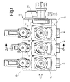
- Fig. 1: eine Seitenansicht der Verteileinrichtung mit Ventilgehäuse und Teilbreitenventilen;
- Fig. 2: einen Schnitt nach der Linie 2-2 in Fig. 1;
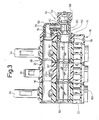
- Fig. 3: einen Schnitt nach der Linie 3-3 in Fig. 2 und
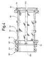
- Fig. 4: einen Schnitt längs einer Durchmesserebene durch ein Filtersegment mit aufgerastetem Anschlußstück.
- 1: a side view of the distribution device with valve housing and section valves;
- Fig. 2: a section along the line 2-2 in Fig. 1;
- Fig. 3: a section along the line 3-3 in Fig. 2 and
- Fig. 4: a section along a diameter plane through a filter segment with a snap-on connector.
Die Fig. 1 zeigt die nicht ganz vollständige Verteileinrichtung 10, die ein Ventilgehäuse 12 besitzt, das aus mehreren Gehäusesegmenten 14 und zwei Gehäuse-Endsegmenten zusammengesetzt ist, von denen nur das Gehäuse-Endsegment 16 gezeichnet wurde. Die verschiedenen Segmente des Ventilgehäuses 12 werden beispielsweise durch nicht dargestellte, als Schrauben ausgebildete Zuganker zusammengehalten. Der stirnseitigen Abdichtung der Gehäusesegmente 14 und 16 gegeneinander dienen dabei O-Ringe 18 und 20, die sich aus Fig. 3 ergeben.1 shows the incomplete distribution device 10, which has a valve housing 12 which is composed of a plurality of
Die Gehäusesegmente 14 bilden mit Durchgangsöffnungen einen Zulauf-Längskanal 22, der von der Spritz- bzw. Sprühflüssigkeit in Richtung des in die Fig. 3 eingezeichneten Pfeils A durchströmt wird. Zweite Durchgangsöffnungen in den Gehäusesegmenten 14 bilden zusammen einen Rücklauf-Längskanal 24, welcher parallel zum Zulauf-Längskanal 22 verläuft.The
Wie besonders deutlich die Fig. 2 erkennen lässt, sind in jedes der Gehäusesegmente 14 ein sogenanntes Teilbreitenventil 26 und eine Gleichdruckdrossel 28 eingebaut. Mit Hilfe des Teilbreitenventils lässt sich der Zulauf-Längskanal 22 wahlweise mit einer Auslassöffnung 30 des betreffenden Gehäusesegments 14 oder mit dem Rücklauf-Längskanal 24 verbinden. Die Auslassöffnung 30 wird dann über einen Schlauch oder dergleichen mit dem zu dem betreffenden Gehäusesegment 14 gehörenden Leitungsabschnitt einer Feldspritzleitung verbunden. Wie bekannt, besitzt das Teilbreitenventil 26 einen um eine Achse 32 schwenkbaren Schnellverschlusshebel 34, mit dessen Hilfe ein Ventil schaft 36 in Richtung des Doppelpfeils B hin- und hergeschoben werden kann. An diesem Ventilschaft ist ein Ventilteller 38 befestigt, welcher mit einem oberen und einem unteren Ventilsitz 40 bzw. 42 zusammenwirkt. In der in Fig. 2 dargestellten Stellung gibt der Ventilteller 38 einen im Gehäusesegment 14 ausgebildeten Durchlass 44 vom Zulauf-Längskanal 22 zur Auslassöffnung 30 frei, während der Zulauflängskanal 22 über einen Durchlass 46 mit dem Rücklauf-Längskanal 24 in Verbindung steht, wenn der Ventilteller 38 gegen den unteren Ventilsitz 42 angelegt wird, was dadurch geschieht, dass man den Schnellverschlusshebel 34 in die in Fig. 2 strichpunktiert dargestellte Schliessstellung schwenkt. Die Gleichdruckdrossel 28, die sich mit Hilfe eines Drehgriffs 50 verstellen lässt, dient dazu, zwischen dem Zulauf-Längskanal 22 und dem Rücklauf-Längskanal 24 eine Drossel einstellbaren Durchlassquerschnitts zu bilden, um den Druckabfall je Gehäusesegment 14 entlang dem Zulauf-Längskanal 22 unabhängig davon zu machen, ob das Teilbreitenventil 26 nun den Durchlass 44 zur Auslassöffnung 30 freigibt oder den Durchlass 46 zum Rücklauf-Längskanal 24.As can be seen particularly clearly in FIG. 2, a so-called
Erfindungsgemäss ist in das Gehäuse-Endsegment 16 ein Reinigungsventil 54 eingebaut, welches einen mit dem Zulauf-Längskanal 22 fluchtenden Einströmkanal 56 und einen Auslaßstutzen 58 besitzt, zwischen denen sich im Gehäuse des Reinigungsventils ein Ventilsitz 60 befindet, der mit einem Ventilglied 62 zusammenwirkt, das sich mittels eines von einem Gewinde 64 gehaltenen Drehgriffs 66 in axialer Richtung verstellen lässt, um einen Durchlass zwischen dem Einströmkanal 56 und dem Auslaßstutzen 58 mehr oder minder zu öffnen. Bei der dargestellten Ausführungsform verbindet ein Rohrkrümmer 70 den Auslaßstutzen 58 mit dem Rücklauf-Längskanal 24, bei einer Drehung des Reinigungsventils 54 um 180° um die Längsachse des Zulauf-Längskanals 22 kann der Auslaßstutzen 58 aber auch einen Ablaßstutzen bilden.According to the invention, a
Nach einem weiteren Merkmal der Erfindung dient eine haarnadelförmige Klammer 74 dazu, das Reinigungsventil 54 im Gehäuseendsegment 16 zu halten. Diese Klammer ist mit ihren beiden Schenkeln in nicht näher dargestellte, quer zur Längsrichtung der Kanäle 22 und 24 verlaufende Bohrungen des Gehäuseendsegments 16 sowie eine Umfangsnut 76 des Reinigungsventils 54 eingesteckt und hält so das letztere am Gehäuseendsegment 16 fest. Der Abdichtung des Reinigungsventils 54 im Gehäuseendsegment 16 dient ein O-Ring 78, der innerhalb der Klammer 74 liegt und so eine Leckage an den erwähnten Querbohrungen verhindert.According to a further feature of the invention, a hairpin-shaped
Wie besonders deutlich die Fig. 3 erkennen lässt, nimmt der Zulauf-Längskanal 22 einen als Ganzes mit 80 bezeichneten Siebzylinder auf, welcher abdichtend gegen das Reinigungsventil 54 stösst. Der Siebzylinder 80 ist aus ebensovielen Filtersegmenten 82 zusammengesetzt, wie das Ventilgehäuse 12 Gehäusesegmente 14 besitzt, und die Fig. 4 zeigt ein solches Filtersegment 82 im Detail.As can be seen particularly clearly in FIG. 3, the inlet
Erfindungsgemäss handelt es sich bei den Filtersegmenten 82 um einstückige Kunststoff-Spritzgußteile mit zwei endseitigen Stirnringen 84 und 86, die durch Längsrippen 88 einstückig miteinander verbunden sind. Diese Längsrippen tragen das eigentliche zylindrische Sieb 90, welches in radialer Richtung nach aussen durch angeformte Verstärkungsringe 92 abgestützt wird.According to the invention, the
Erfindungsgemäss sind die Stirnringe 84 und 86 mit komplementär ausgebildeten Rastelementen 94 und 96 versehen, welche vorteilhafterweise die Gestalt angeformter kurzer Stutzen besitzen, um so eine steife Verbindung zwischen den Filtersegmenten 82 herbeiführen zu können. Um das Ein- und Ausrasten der Filtersegmente aneinander zu erleichtern, besitzen die stutzenförmigen Rastelemente 94 und 96 an ihrem Umfang mehrere Schlitze 100.According to the invention, the
Der Befestigung des Siebzylinders 80 im Ventilgehäuse 12 dient ein in Fig. 4 gezeigtes Anschlußstück 102, welches eine Umfangsnut 104 besitzt, um mit Hilfe einer Klammer 74 in derselben Weise an einem nicht dargestellten Gehäuse-Endsegment gehalten zu werden, wie dies beim Reinigungsventil 54 der Fall ist. Zweckmässigerweise dient auch am Anschlußstück 102 ein nicht dargestellter O-Ring der Abdichtung, so wie dies anhand des Reinigungsventils 54 beschrieben worden ist.The attachment of the
Da die Siebe 90 in radialer Richtung von innen nach aussen durchströmt werden, lagert sich Schmutz an der Innenseite des Siebs 90 ab. Die erfindungsgemässe Verteileinrichtung 10 erlaubt nun eine Spülung des Siebzylinders 80 dadurch, dass das Reinigungsventil 54 geöffnet wird, um so abgelagerten Schmutz in den Rücklauf-Längskanal 24 zu spülen oder, wenn der Auslaßstutzen 58 nicht mit dem Rücklauf-Längskanal 24 verbunden ist, ein Ausschwemmen des Schmutzes ins Freie zu ermöglichen.Since the
Die erfindungsgemässe Verteileinrichtung 10 erlaubt eine Sichtkontrolle des Siebzylinders 80. Zu diesem Zweck ist in jedes der Gehäusesegmente 14 eine Öffnung 110 eingeformt, die sich mittels eines Stopfens 112 druckdicht verschliessen lässt, wobei der Stopfen mit einer Klammer 74 in derselben Weise gehalten werden kann, wie dies beim Reinigungsventil 54 der Fall ist. Die Achse der Öffnung 110 ist erfindungsgemäss auf die Längsachse des Zulauf-Längskanals 22 gerichtet, so dass man den Siebzylinder durch die aus klartransparentem Kunststoff bestehenden Stopfen 112 hindurch auf den Grad seiner Verschmutzung hin überprüfen kann.The distribution device 10 according to the invention allows a visual inspection of the
Wie die Fig. 2 deutlich erkennen lässt, erleichtern die Öffnungen 110 zusammen mit den Durchlässen 44 auch die Montage der Teilbreitenventile 26.As can be clearly seen in FIG. 2, the
Wie die Fig. 4 erkennen lässt, ist das Anschlußstück 102 erfindungsgemäss mit einem Rastelement 96ʹ versehen, welches dem Rastelement 96 der Filtersegmente 82 entspricht, so dass sich das Anschlußstück 102 auf das erste Filtersegment 82 des Siebzylinders 80 aufrasten lässt.4, the
Natürlich wird eine Erfindung schon in dem Gedanken gesehen, den Siebzylinder im Zulauf-Längskanal 22 unterzubringen, um so ein besonderes Filtergehäuse einsparen zu können. Dieser Vorteil würde ja auch dann erzielt werden, wenn der Siebzylinder 80 nicht aus einzelnen Filtersegmenten 82 zusammengesetzt wäre.Of course, an invention is already seen in the idea of accommodating the screen cylinder in the inlet
Wenn der Siebzylinder 80 nicht segmentiert ist, kann auch auf ein Zusammensetzen des Ventilgehäuses 12 aus einzelnen Segmenten verzichtet werden.If the
Der Rücklauf-Längskanal muss nicht unbedingt innerhalb des Ventilgehäuses liegen, da es nur erforderlich ist, dass sich der Zulauf-Längskanal durch die Teilbreitenventile mit einer Rücklaufleitung verbinden lässt.The return longitudinal channel does not necessarily have to be inside the valve housing, since it is only necessary that the longitudinal inlet channel can be connected to a return line by the section valves.
Die erfindungsgemässe Ventileinrichtung besitzt auch den Vorteil, dass sie die Einstellarmatur insgesamt kompakter werden lässt, da ein separates Druckfiltergehäuse entfällt.The valve device according to the invention also has the advantage that it makes the adjustment fitting more compact overall, since a separate pressure filter housing is not required.
Claims (10)
Priority Applications (1)
| Application Number | Priority Date | Filing Date | Title |
|---|---|---|---|
| AT87110288T ATE48065T1 (en) | 1986-07-18 | 1987-07-16 | ADJUSTMENT FITTING FOR FIELD SPRAY LINES. |
Applications Claiming Priority (2)
| Application Number | Priority Date | Filing Date | Title |
|---|---|---|---|
| DE3624425A DE3624425C2 (en) | 1986-07-18 | 1986-07-18 | Adjustment fitting for field spray lines |
| DE3624425 | 1986-07-18 |
Publications (2)
| Publication Number | Publication Date |
|---|---|
| EP0253388A1 true EP0253388A1 (en) | 1988-01-20 |
| EP0253388B1 EP0253388B1 (en) | 1989-11-23 |
Family
ID=6305531
Family Applications (1)
| Application Number | Title | Priority Date | Filing Date |
|---|---|---|---|
| EP87110288A Expired EP0253388B1 (en) | 1986-07-18 | 1987-07-16 | Control device for field spraying conduits |
Country Status (3)
| Country | Link |
|---|---|
| EP (1) | EP0253388B1 (en) |
| AT (1) | ATE48065T1 (en) |
| DE (1) | DE3624425C2 (en) |
Cited By (2)
| Publication number | Priority date | Publication date | Assignee | Title |
|---|---|---|---|---|
| CN103820618A (en) * | 2014-02-19 | 2014-05-28 | 安徽省宁国市华达耐磨材料有限公司 | Quenching liquid cooling device |
| CN104206098A (en) * | 2014-09-25 | 2014-12-17 | 山东农业大学 | Wheat and corn annual production variable fertilizer and water integrated irrigation system |
Families Citing this family (1)
| Publication number | Priority date | Publication date | Assignee | Title |
|---|---|---|---|---|
| DE102018114908B4 (en) * | 2018-06-21 | 2022-04-21 | Amazonen-Werke H. Dreyer SE & Co. KG | Agricultural sprayer |
Citations (4)
| Publication number | Priority date | Publication date | Assignee | Title |
|---|---|---|---|---|
| US2641280A (en) * | 1948-06-23 | 1953-06-09 | Henry G Fleischhauer | Automatic control valve for branch pipe lines |
| FR2347593A1 (en) * | 1976-04-05 | 1977-11-04 | Boisserand Marc | FLUID DISTRIBUTOR AND FLUID DISPENSER CELL OBTAINED FROM CELLS OF THIS TYPE |
| FR2350051A1 (en) * | 1976-05-04 | 1977-12-02 | Ollivier Jean | DEVICE FOR AUTOMATIC AND SELECTIVE WATERING OF PLANTATIONS |
| EP0169260A1 (en) * | 1983-03-09 | 1986-01-29 | Siegfried Böhnisch | Combined branch and valve element for cold water distribution networks |
Family Cites Families (1)
| Publication number | Priority date | Publication date | Assignee | Title |
|---|---|---|---|---|
| DE3412739A1 (en) * | 1984-04-05 | 1985-10-17 | Gardena Kress + Kastner Gmbh, 7900 Ulm | CONNECTING DEVICE FOR IRRIGATION PLANTS |
-
1986
- 1986-07-18 DE DE3624425A patent/DE3624425C2/en not_active Expired - Fee Related
-
1987
- 1987-07-16 EP EP87110288A patent/EP0253388B1/en not_active Expired
- 1987-07-16 AT AT87110288T patent/ATE48065T1/en not_active IP Right Cessation
Patent Citations (4)
| Publication number | Priority date | Publication date | Assignee | Title |
|---|---|---|---|---|
| US2641280A (en) * | 1948-06-23 | 1953-06-09 | Henry G Fleischhauer | Automatic control valve for branch pipe lines |
| FR2347593A1 (en) * | 1976-04-05 | 1977-11-04 | Boisserand Marc | FLUID DISTRIBUTOR AND FLUID DISPENSER CELL OBTAINED FROM CELLS OF THIS TYPE |
| FR2350051A1 (en) * | 1976-05-04 | 1977-12-02 | Ollivier Jean | DEVICE FOR AUTOMATIC AND SELECTIVE WATERING OF PLANTATIONS |
| EP0169260A1 (en) * | 1983-03-09 | 1986-01-29 | Siegfried Böhnisch | Combined branch and valve element for cold water distribution networks |
Cited By (3)
| Publication number | Priority date | Publication date | Assignee | Title |
|---|---|---|---|---|
| CN103820618A (en) * | 2014-02-19 | 2014-05-28 | 安徽省宁国市华达耐磨材料有限公司 | Quenching liquid cooling device |
| CN104206098A (en) * | 2014-09-25 | 2014-12-17 | 山东农业大学 | Wheat and corn annual production variable fertilizer and water integrated irrigation system |
| CN104206098B (en) * | 2014-09-25 | 2015-12-30 | 山东农业大学 | Wheat and corn whole year production variable rich water integration irrigation system |
Also Published As
| Publication number | Publication date |
|---|---|
| EP0253388B1 (en) | 1989-11-23 |
| DE3624425A1 (en) | 1988-01-28 |
| ATE48065T1 (en) | 1989-12-15 |
| DE3624425C2 (en) | 1995-12-07 |
Similar Documents
| Publication | Publication Date | Title |
|---|---|---|
| EP0023582B1 (en) | Column for high pressure liquid chromatography and its use | |
| DE2643697C2 (en) | Device for rinsing dirt out of a liquid circulation system | |
| DE2313983C2 (en) | Device for controlling and / or conditioning a fluid with at least one control or conditioning device | |
| DE69825231T2 (en) | switching valve | |
| DE1928220B2 (en) | Device for the treatment of liquid or gaseous media | |
| EP1246680A1 (en) | Filter device | |
| DE2724429A1 (en) | MANUAL WATER MIXING VALVE | |
| DE3443752C2 (en) | ||
| EP0253388B1 (en) | Control device for field spraying conduits | |
| DE19827992A1 (en) | Retrofitting device for installing fluid flow meter in pressurized pipeline | |
| DE2733718A1 (en) | FILTER DESIGN | |
| EP0401633A2 (en) | Backwashable filter mounting | |
| EP0351664B1 (en) | Device for cleaning pipe-lines, in particular beer lines | |
| EP1245258A2 (en) | Device for cleaning, especially for filtering liquids | |
| DE2716831C2 (en) | Mixing valve | |
| DE19512143C1 (en) | Pressure limiting valve with changeover piston | |
| EP1213519A2 (en) | Radiator valve | |
| DE3925270C2 (en) | ||
| DE10316274B3 (en) | Pressure reduction device for domestic water supply system with cylindrical dirt catchment device and relatively rotatable reverse rinsing flow device | |
| DE10012066B4 (en) | Multi-way valve (pilot valve container) | |
| DE4235723A1 (en) | Multi-way ball cock for gases and fluids - has two balls connected together rotationally secured by spacer adjoining bore in housing containing balls | |
| DE202006015137U1 (en) | Pond pump, has suction channels that are arranged opposite to housing and flow distribution device that is provided to divide suction volume of suction connection on two suction channels | |
| DE102017102308A1 (en) | Valve with a device for presetting the flow channel cross-section | |
| DE3243268A1 (en) | WATER MIXING TAP | |
| DE2742333C2 (en) | Loosening device |
Legal Events
| Date | Code | Title | Description |
|---|---|---|---|
| PUAI | Public reference made under article 153(3) epc to a published international application that has entered the european phase |
Free format text: ORIGINAL CODE: 0009012 |
|
| AK | Designated contracting states |
Kind code of ref document: A1 Designated state(s): AT BE CH FR GB LI NL SE |
|
| 17P | Request for examination filed |
Effective date: 19880125 |
|
| 17Q | First examination report despatched |
Effective date: 19890125 |
|
| GRAA | (expected) grant |
Free format text: ORIGINAL CODE: 0009210 |
|
| AK | Designated contracting states |
Kind code of ref document: B1 Designated state(s): AT BE CH FR GB LI NL SE |
|
| REF | Corresponds to: |
Ref document number: 48065 Country of ref document: AT Date of ref document: 19891215 Kind code of ref document: T |
|
| ET | Fr: translation filed | ||
| GBT | Gb: translation of ep patent filed (gb section 77(6)(a)/1977) | ||
| REG | Reference to a national code |
Ref country code: GB Ref legal event code: 727 |
|
| REG | Reference to a national code |
Ref country code: GB Ref legal event code: 727A |
|
| PLBE | No opposition filed within time limit |
Free format text: ORIGINAL CODE: 0009261 |
|
| STAA | Information on the status of an ep patent application or granted ep patent |
Free format text: STATUS: NO OPPOSITION FILED WITHIN TIME LIMIT |
|
| 26N | No opposition filed | ||
| REG | Reference to a national code |
Ref country code: GB Ref legal event code: 727B |
|
| REG | Reference to a national code |
Ref country code: GB Ref legal event code: SP |
|
| EAL | Se: european patent in force in sweden |
Ref document number: 87110288.5 |
|
| PGFP | Annual fee paid to national office [announced via postgrant information from national office to epo] |
Ref country code: BE Payment date: 19950510 Year of fee payment: 9 |
|
| PGFP | Annual fee paid to national office [announced via postgrant information from national office to epo] |
Ref country code: CH Payment date: 19950531 Year of fee payment: 9 |
|
| PGFP | Annual fee paid to national office [announced via postgrant information from national office to epo] |
Ref country code: AT Payment date: 19950622 Year of fee payment: 9 |
|
| PGFP | Annual fee paid to national office [announced via postgrant information from national office to epo] |
Ref country code: GB Payment date: 19950705 Year of fee payment: 9 |
|
| PGFP | Annual fee paid to national office [announced via postgrant information from national office to epo] |
Ref country code: FR Payment date: 19960430 Year of fee payment: 10 |
|
| PGFP | Annual fee paid to national office [announced via postgrant information from national office to epo] |
Ref country code: SE Payment date: 19960513 Year of fee payment: 10 |
|
| PG25 | Lapsed in a contracting state [announced via postgrant information from national office to epo] |
Ref country code: GB Effective date: 19960716 Ref country code: AT Effective date: 19960716 |
|
| PG25 | Lapsed in a contracting state [announced via postgrant information from national office to epo] |
Ref country code: LI Effective date: 19960731 Ref country code: CH Effective date: 19960731 Ref country code: BE Effective date: 19960731 |
|
| PGFP | Annual fee paid to national office [announced via postgrant information from national office to epo] |
Ref country code: NL Payment date: 19960731 Year of fee payment: 10 |
|
| BERE | Be: lapsed |
Owner name: GEBR. HOLDER G.M.B.H. & CO. Effective date: 19960731 |
|
| GBPC | Gb: european patent ceased through non-payment of renewal fee |
Effective date: 19960716 |
|
| REG | Reference to a national code |
Ref country code: CH Ref legal event code: PL |
|
| PG25 | Lapsed in a contracting state [announced via postgrant information from national office to epo] |
Ref country code: SE Effective date: 19970717 |
|
| PG25 | Lapsed in a contracting state [announced via postgrant information from national office to epo] |
Ref country code: NL Free format text: LAPSE BECAUSE OF NON-PAYMENT OF DUE FEES Effective date: 19980201 |
|
| PG25 | Lapsed in a contracting state [announced via postgrant information from national office to epo] |
Ref country code: FR Free format text: LAPSE BECAUSE OF NON-PAYMENT OF DUE FEES Effective date: 19980331 |
|
| NLV4 | Nl: lapsed or anulled due to non-payment of the annual fee |
Effective date: 19980201 |
|
| EUG | Se: european patent has lapsed |
Ref document number: 87110288.5 |
|
| REG | Reference to a national code |
Ref country code: FR Ref legal event code: ST |