EP1245258A2 - Device for cleaning, especially for filtering liquids - Google Patents
Device for cleaning, especially for filtering liquids Download PDFInfo
- Publication number
- EP1245258A2 EP1245258A2 EP02450026A EP02450026A EP1245258A2 EP 1245258 A2 EP1245258 A2 EP 1245258A2 EP 02450026 A EP02450026 A EP 02450026A EP 02450026 A EP02450026 A EP 02450026A EP 1245258 A2 EP1245258 A2 EP 1245258A2
- Authority
- EP
- European Patent Office
- Prior art keywords
- adjusting rod
- housing
- flushing opening
- opening
- flushing
- Prior art date
- Legal status (The legal status is an assumption and is not a legal conclusion. Google has not performed a legal analysis and makes no representation as to the accuracy of the status listed.)
- Withdrawn
Links
- 239000007788 liquid Substances 0.000 title claims abstract description 18
- 238000001914 filtration Methods 0.000 title claims abstract description 4
- 238000004140 cleaning Methods 0.000 title claims description 4
- 238000011010 flushing procedure Methods 0.000 claims abstract description 24
- XLYOFNOQVPJJNP-UHFFFAOYSA-N water Substances O XLYOFNOQVPJJNP-UHFFFAOYSA-N 0.000 claims abstract description 4
- 238000007789 sealing Methods 0.000 claims description 9
- 238000011001 backwashing Methods 0.000 claims description 6
- 239000000463 material Substances 0.000 claims description 3
- 230000006835 compression Effects 0.000 description 3
- 238000007906 compression Methods 0.000 description 3
- 239000012535 impurity Substances 0.000 description 3
- 238000006073 displacement reaction Methods 0.000 description 2
- 230000013011 mating Effects 0.000 description 2
- 230000004913 activation Effects 0.000 description 1
- 239000000356 contaminant Substances 0.000 description 1
- 238000011109 contamination Methods 0.000 description 1
- 239000003344 environmental pollutant Substances 0.000 description 1
- 230000001771 impaired effect Effects 0.000 description 1
- 230000007257 malfunction Effects 0.000 description 1
- 238000004519 manufacturing process Methods 0.000 description 1
- 238000000034 method Methods 0.000 description 1
- 231100000719 pollutant Toxicity 0.000 description 1
- 239000004576 sand Substances 0.000 description 1
Images


Classifications
-
- B—PERFORMING OPERATIONS; TRANSPORTING
- B01—PHYSICAL OR CHEMICAL PROCESSES OR APPARATUS IN GENERAL
- B01D—SEPARATION
- B01D29/00—Filters with filtering elements stationary during filtration, e.g. pressure or suction filters, not covered by groups B01D24/00 - B01D27/00; Filtering elements therefor
- B01D29/11—Filters with filtering elements stationary during filtration, e.g. pressure or suction filters, not covered by groups B01D24/00 - B01D27/00; Filtering elements therefor with bag, cage, hose, tube, sleeve or like filtering elements
- B01D29/13—Supported filter elements
- B01D29/23—Supported filter elements arranged for outward flow filtration
-
- B—PERFORMING OPERATIONS; TRANSPORTING
- B01—PHYSICAL OR CHEMICAL PROCESSES OR APPARATUS IN GENERAL
- B01D—SEPARATION
- B01D29/00—Filters with filtering elements stationary during filtration, e.g. pressure or suction filters, not covered by groups B01D24/00 - B01D27/00; Filtering elements therefor
- B01D29/62—Regenerating the filter material in the filter
- B01D29/64—Regenerating the filter material in the filter by scrapers, brushes, nozzles, or the like, acting on the cake side of the filtering element
- B01D29/6469—Regenerating the filter material in the filter by scrapers, brushes, nozzles, or the like, acting on the cake side of the filtering element scrapers
- B01D29/6484—Regenerating the filter material in the filter by scrapers, brushes, nozzles, or the like, acting on the cake side of the filtering element scrapers with a translatory movement with respect to the filtering element
-
- B—PERFORMING OPERATIONS; TRANSPORTING
- B01—PHYSICAL OR CHEMICAL PROCESSES OR APPARATUS IN GENERAL
- B01D—SEPARATION
- B01D35/00—Filtering devices having features not specifically covered by groups B01D24/00 - B01D33/00, or for applications not specifically covered by groups B01D24/00 - B01D33/00; Auxiliary devices for filtration; Filter housing constructions
- B01D35/14—Safety devices specially adapted for filtration; Devices for indicating clogging
- B01D35/153—Anti-leakage or anti-return valves
-
- B—PERFORMING OPERATIONS; TRANSPORTING
- B01—PHYSICAL OR CHEMICAL PROCESSES OR APPARATUS IN GENERAL
- B01D—SEPARATION
- B01D35/00—Filtering devices having features not specifically covered by groups B01D24/00 - B01D33/00, or for applications not specifically covered by groups B01D24/00 - B01D33/00; Auxiliary devices for filtration; Filter housing constructions
- B01D35/16—Cleaning-out devices, e.g. for removing the cake from the filter casing or for evacuating the last remnants of liquid
Definitions
- the subject invention relates to a device for cleaning, in particular for filtering liquids, such as water, consisting of a a housing containing a filter insert, which with connections for the Inlet and for the discharge of the liquid as well as with a flushing opening is formed, furthermore an adjustable by an adjusting rod in the housing Valve body is provided, in the open positions of backwashing of the filter insert and the liquid with the filtered material is discharged through the flushing opening.
- a device for cleaning in particular for filtering liquids, such as water, consisting of a a housing containing a filter insert, which with connections for the Inlet and for the discharge of the liquid as well as with a flushing opening is formed, furthermore an adjustable by an adjusting rod in the housing Valve body is provided, in the open positions of backwashing of the filter insert and the liquid with the filtered material is discharged through the flushing opening.
- the adjusting rod is provided with radially protruding plate-shaped elements formed which provide channels are to which at least one backwash channel connects.
- the adjusting rod is provided with a thread, their axial adjustment by their rotation in a in the housing provided counter thread takes place.
- This training is therefore disadvantageous because the thread required for this and the mating thread assigned to it require a large manufacturing effort, because the Threads are impaired in their function due to contamination can, since the actuating speed is also relatively low, resulting in a large consumption of rinsing liquid is required and there is an automatic Adjustment is only possible with a high level of technical effort.
- the object of the invention is therefore based on the object To create device in which the adhering to the known device Disadvantages are avoided. According to the invention, this is achieved by that the actuating rod is assigned a return spring and that the actuating rod against the action of the return spring for opening the valve and is displaceable for backwashing the filter insert.
- the adjusting rod which passes through the approximately cylindrical housing in its longitudinal direction and is formed at one end with an adjusting handle and protrudes with its other end into the flushing opening, is formed with a stop in the area assigned to the adjusting handle, the adjusting spring between the inner wall of the housing and the stop.
- the adjusting rod can be formed at its end assigned to the flushing opening with a sealing element assigned to the flushing opening.
- a plurality of spaced-apart, plate-shaped elements are provided on the adjusting rod, the outer edge of which rests on the inner surface of the filter element and which are formed with channels to which at least one flushing channel runs along the adjusting rod and which opens near the flushing opening
- the adjusting rod is formed by a rod, at one end of which the actuating button and at the other end of which the sealing element are arranged.
- the adjusting rod can be surrounded by a sleeve which is hollow-cylindrical in its end associated with the flushing opening, a seal being associated with the hollow-cylindrical region in the interior of the housing.
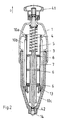
- the device shown in FIGS. 1 and 2 consists of a two-part, cylindrical housing 1 with openings 11 and 12, to which a connector 2 is attached, the inlet pipe 21 of which is assigned to the inlet opening 11 and the outlet pipe 22 of which is assigned to the outlet opening 12.
- a filter insert 3 In the interior of the housing 1 there is a filter insert 3, through which the interior is divided into two areas 10a and 10b.
- the housing 1 is penetrated by an adjusting rod 4, which is formed at its upper end with an adjusting handle 41 and the lower end of which is provided with a sealing element 42, through which a flushing opening 14 provided at the lower end of the housing 1 can be closed or released ,
- an adjusting rod 4 which is formed at its upper end with an adjusting handle 41 and the lower end of which is provided with a sealing element 42, through which a flushing opening 14 provided at the lower end of the housing 1 can be closed or released .
- the actuating rod 4 Over the length of the actuating rod 4, it is formed with three plate-shaped elements 6, which project radially from the actuating rod 4 and whose outer end faces bear against the inner surface 31 of the filter insert 3.
- the adjusting rod 4 is surrounded by a helical compression spring 5, which rests on the one hand against the inner surface of the housing 1 and on the other hand against a stop 45 provided on the adjusting rod 4.
- the adjusting rod 4 is surrounded by a sleeve 7, which interacts with the plate-shaped elements 6.
- a sealing ring 13 is provided, to which a cylindrical part 70 of the sleeve 7 is assigned.
- the plate-shaped elements 6 from two plates 61 and 62, between which there is an outer ring channel 63, two being radial to the ring channel 63 Connect running channels 64.
- the channels 64 go into two within the Sleeve 7 located longitudinal channels 71 and open into a below the Seal 13 located space 10c.
- the plate-shaped elements 6 formed with recesses 65.
- the function of this device is as follows:
- the inflow pipe 21 is connected to the supply network and a consumer is connected via the outflow pipe 22 with the activation of a shut-off valve.
- liquid in particular water
- the filter insert 3 contains impurities, pollutants, foreign bodies and the like contained in the medium. filtered out.
- the adjusting rod 4 is displaced in the direction of arrow D by means of the adjusting handle 41 against the action of the return spring 5.
- the end position of this shift is shown in Fig. 4.
- the flushing opening 14 is released by the sealing body 42, as a result of which liquid flows from the inner space 10a between the sleeve 7 and the sealing ring 13 into the space 10c and flows out through the flushing opening 14. In this way, contaminants, such as sand, located in the space 10c are discharged therefrom.
- the liquid flows again through the filter insert 3 into the ring channels 63 located in the plate-shaped elements 6 and further into the radial channels 64, as a result of which it flows out through the axial channels 71 and emerges from the housing 1 through the flushing opening 14 ,
- the plate-shaped elements 6 slide up along the inner surface 31 of the filter insert 3, as a result of which the liquid flows through it over its entire length in the opposite direction to the operational flow.
- This backwash removes the impurities in the filter insert 3 and removes them from the housing 1 through the flushing opening 14.
- control knob 41 As soon as the control knob 41 is released, the control rod 4 is activated by the Helical compression spring 5 back to its initial position, in which the flushing opening 14 is closed, adjusted back.
Abstract
Description
Die gegenständliche Erfindung betrifft eine Einrichtung zur Reinigung, insbesondere zur Filterung, von Flüssigkeiten, wie Wasser, bestehend aus einem einen Filtereinsatz enthaltenden Gehäuse, welches mit Anschlüssen für die Zuleitung und für die Ableitung der Flüssigkeit sowie mit einer Spülöffnung ausgebildet ist, wobei weiters im Gehäuse ein durch eine Stellstange verstellbarer Ventilkörper vorgesehen ist, in dessen offenen Stellungen eine Rückspülung des Filtereinsatzes erfolgt und die Flüssigkeit mit dem ausgefilterten Material durch die Spülöffnung hindurch ausgetragen wird.The subject invention relates to a device for cleaning, in particular for filtering liquids, such as water, consisting of a a housing containing a filter insert, which with connections for the Inlet and for the discharge of the liquid as well as with a flushing opening is formed, furthermore an adjustable by an adjusting rod in the housing Valve body is provided, in the open positions of backwashing of the filter insert and the liquid with the filtered material is discharged through the flushing opening.
Bei bekannten derartigen Einrichtungen ist die Stellstange mit radial abragenden, plattenförmigen Elementen ausgebildet, welche mit Kanälen versehen sind, an welche mindestens ein Rückspülkanal anschließt. Durch eine axiale Verstellung der Stellstange wird einerseits das Ventil betätigt, wodurch die Spülöffnung freigegeben wird und werden andererseits die plattenförmigen Elemente längs der Innenseite des Filtereinsatzes verschoben, wodurch mittels der zugeführten Flüssigkeit die angestrebte Reinigung des Filtereinsatzes erfolgt und das ausgefilterte Material durch die Spülöffnung hindurch aus dem Gehäuse ausgetragen wird.In known devices of this type, the adjusting rod is provided with radially protruding plate-shaped elements formed which provide channels are to which at least one backwash channel connects. By an axial Adjustment of the actuating rod, on the one hand, actuates the valve, causing the Rinsing opening is released and on the other hand, the plate-shaped Elements moved along the inside of the filter insert, which means The desired cleaning of the filter insert takes place in the liquid supplied and the filtered material through the flushing opening from the Housing is carried out.
Bei den bekannten Einrichtungen ist die Stellstange mit einem Gewinde versehen, wobei deren axiale Verstellung durch deren Verdrehung in einem im Gehäuse vorgesehenen Gegengewinde erfolgt. Diese Ausbildung ist deshalb nachteilig, da das hierfür erforderliche Gewinde und das diesem zugeordnete Gegengewinde einen großen fertigungstechnischen Aufwand erfordern, da die Gewinde infolge von Verschmutzungen in ihrer Funktion beeinträchtigt werden können, da weiters die Stellgeschwindigkeit relativ gering ist, wodurch ein großer Verbrauch an Spülflüssigkeit bedingt wird und da eine automatische Verstellung nur mit einem hohen technischen Aufwand möglich ist.In the known devices, the adjusting rod is provided with a thread, their axial adjustment by their rotation in a in the housing provided counter thread takes place. This training is therefore disadvantageous because the thread required for this and the mating thread assigned to it require a large manufacturing effort, because the Threads are impaired in their function due to contamination can, since the actuating speed is also relatively low, resulting in a large consumption of rinsing liquid is required and there is an automatic Adjustment is only possible with a high level of technical effort.
Der gegenständlichen Erfindung liegt somit die Aufgabe zugrunde, eine derartige Einrichtung zu schaffen, bei welcher die der bekannten Einrichtung anhaftenden Nachteile vermieden werden. Dies wird erfindungsgemäß dadurch erzielt, daß der Stellstange eine Rückstellfeder zugeordnet ist und daß die Stellstange entgegen der Wirkung der Rückstellfeder zur Öffnung des Ventiles und zur Rückspülung des Filtereinsatzes verschiebbar ist. The object of the invention is therefore based on the object To create device in which the adhering to the known device Disadvantages are avoided. According to the invention, this is achieved by that the actuating rod is assigned a return spring and that the actuating rod against the action of the return spring for opening the valve and is displaceable for backwashing the filter insert.
Vorzugsweise ist die Stellstange, welche das angenähert zylindrisch ausgebildete
Gehäuse in dessen Längsrichtung durchsetzt und an ihrem einen Ende
mit einem Stellgriff ausgebildet ist sowie mit ihrem anderen Ende in die
Spülöffnung einragt, in dem dem Stellgriff zugeordneten Bereich mit einem
Anschlag ausgebildet, wobei sich die Stellfeder zwischen der Innenwand des
Gehäuses und dem Anschlag befindet. Weiters kann die Stellstange an ihrem
der Spülöffnung zugeordneten Ende mit einem der Spülöffnung zugeordneten
Dichtungselement ausgebildet sein.
Nach weiteren bevorzugten Merkmalen sind an der Stellstange mehrere im
Abstand voneinander angeordnete, plattenförmige Elemente vorgesehen, deren
äußerer Rand an die Innenfläche des Filterelementes anliegt und welche mit
Kanälen ausgebildet sind, an welche mindestens ein längs der Stellstange verlaufender
Spülkanal anschließt, welcher nahe der Spülöffnung mündet. Insbesondere
ist die Stellstange durch einen Stab gebildet, an dessen einem Ende
der Betätigungsknopf und an dessen anderem Ende das Dichtungselement angeordnet
sind. Weiters kann die Stellstange von einer Hülse umgeben sein,
welche in ihrem der Spülöffnung zugeordneten Ende hohlzylindrisch ausgebildet
ist, wobei dem hohlzylindrischen Bereich im Innenraum des Gehäuses eine
Dichtung zugeordnet ist.Preferably, the adjusting rod, which passes through the approximately cylindrical housing in its longitudinal direction and is formed at one end with an adjusting handle and protrudes with its other end into the flushing opening, is formed with a stop in the area assigned to the adjusting handle, the adjusting spring between the inner wall of the housing and the stop. Furthermore, the adjusting rod can be formed at its end assigned to the flushing opening with a sealing element assigned to the flushing opening.
According to further preferred features, a plurality of spaced-apart, plate-shaped elements are provided on the adjusting rod, the outer edge of which rests on the inner surface of the filter element and which are formed with channels to which at least one flushing channel runs along the adjusting rod and which opens near the flushing opening , In particular, the adjusting rod is formed by a rod, at one end of which the actuating button and at the other end of which the sealing element are arranged. Furthermore, the adjusting rod can be surrounded by a sleeve which is hollow-cylindrical in its end associated with the flushing opening, a seal being associated with the hollow-cylindrical region in the interior of the housing.
Der Gegenstand der Erfindung ist nachstehend anhand eines in der Zeichnung dargestellten Ausführungsbeipieles näher erläutert. Es zeigen:
- Fig. 1
- eine erfindungsgemäße Einrichtung in der ersten Betriebsstellung und in einem axialen Längsschnitt,
- Fig. 2
- die Einrichtung gemäß Fig. 1 in einem um 90° versetzten, zweiten axialen Längsschnitt,
- die Fig. 3
- ein Detail der Fig. 2, in einer gegenüber dieser vergrößerten Darstellung,
- die Fig. 3a, 3b und 3c
- die Schnitte gemäß den Linien A-A, B-B und C-C der Fig. 3, und
- Fig. 4
- die Einrichtung gemäß Fig. 1, in einer zweiten Betriebsstellung und im ersten axialen Längsschnitt.
- Fig. 1
- a device according to the invention in the first operating position and in an axial longitudinal section,
- Fig. 2
- 1 in a second axial longitudinal section offset by 90 °,
- 3
- 3 shows a detail of FIG. 2, in an enlarged representation compared to this,
- 3a, 3b and 3c
- the sections along the lines AA, BB and CC of Fig. 3, and
- Fig. 4
- 1 in a second operating position and in the first axial longitudinal section.
Die in den Fig. 1 und 2 dargestellte Einrichtung besteht aus einem zweiteiligen,
zylinderartigen Gehäuse 1 mit Öffnungen 11 und 12, an welches ein Anschlußstück
2 angesetzt ist, dessen Zuflußrohr 21 der Eintrittsöffnung 11 zugeordnet
ist und dessen Abflußrohr 22 der Austrittsöffnung 12 zugeordnet ist.
Im Innenraum des Gehäuses 1 befindet sich ein Filtereinsatz 3, durch welchen
der Innenraum in zwei Bereiche 10a und 10b unterteilt wird. Weiters ist
das Gehäuse 1 von einer Stellstange 4 durchsetzt, welche an ihrem oberen Ende
mit einem Stellgriff 41 ausgebildet ist und deren unteres Ende mit einem
Dichtungselement 42 versehen ist, durch welches eine am unteren Ende des
Gehäuses 1 vorgesehene Spülöffnung 14 verschließbar bzw. freigebbar ist.
Über die Länge der Stellstange 4 ist diese mit drei plattenförmigen Elementen
6 ausgebildet, welche von der Stellstange 4 radial abragen und deren äußere
Stirnflächen an die Innenfläche 31 des Filtereinsatzes 3 anliegen.
In ihrem oberen Bereich ist die Stellstange 4 von einer Schraubendruckfeder 5
umgeben, welche einerseits an die Innenfläche des Gehäuses 1 und andererseits
an einen an der Stellstange 4 vorgesehenen Anschlag 45 anliegt. Unterhalb
der Schraubendruckfeder 5 ist die Stellstange 4 von einer Hülse 7 umgeben,
welche mit den plattenförmigen Elementen 6 zusammenwirkt.
Am unteren Ende des Innenraumes des Gehäuses 1 ist ein Dichtungsring 13
vorgesehen, welchem ein zylindrischer Teil 70 der Hülse 7 zugeordnet ist.The device shown in FIGS. 1 and 2 consists of a two-part,
In its upper region, the adjusting
At the lower end of the interior of the
Wie dies weiters aus den Fig. 3, 3a, 3b und 3c ersichtlich ist, bestehen die
plattenförmigen Elemente 6 aus zwei Platten 61 und 62, zwischen welchen
sich ein äußerer Ringkanal 63 befindet, wobei an den Ringkanal 63 zwei radial
verlaufende Kanäle 64 anschließen. Die Kanäle 64 gehen in zwei innerhalb der
Hülse 7 befindliche Längskanäle 71 über und münden in einem unterhalb der
Dichtung 13 befindlichen Raum 10c. Weiters sind die plattenförmigen Elemente
6 mit Ausnehmungen 65 ausgebildet.As can also be seen from FIGS. 3, 3a, 3b and 3c, the
plate-
Die Funktion dieser Einrichtung ist wie folgt:
Das Zuflußrohr 21 ist an das Versorgungsnetz angeschlossen und über das
Abflußrohr 22 ist unter Einschaltung eines Sperrventiles ein Verbraucher angeschlossen.
Sobald das Sperrventil geöffnet wird, strömt über das Zuflußrohr
21 und die Zuflußöffnung 11 Flüssigkeit, insbesondere Wasser, in den inneren
Raum 10a ein, wobei sie durch die in den plattenförmigen Elementen 66
befindlichen Ausnehmungen 65 hindurchströmt. Weiters tritt sie durch den
Filtereinsatz 3 hindurch, strömt sie durch den äußeren Raum 10b ein und
strömt sie durch die Abflußöffnung 12 und das Abflußrohr 22 ab. Durch den
Filtereinsatz 3 werden im Medium enthaltene Verunreinigungen, Schadstoffe,
Fremdkörper u.dgl. ausgefiltert. The function of this device is as follows:
The
Sobald eine Reinigung des Filterkörpers 3 von den in diesem enthaltenen Verunreinigungen
usw. erfolgen soll, wird die Stellstange 4 mittels des Stellgriffes
41 entgegen der Wirkung der Rückstellfeder 5 in Richtung des Pfeiles D verschoben.
Die Endstellung dieser Verschiebung ist in Fig. 4 dargestellt.
Durch den Beginn dieser Verschiebung wird die Spülöffnung 14 vom Dichtungskörper
42 freigegeben, wodurch aus dem inneren Raum 10a Flüssigkeit
zwischen der Hülse 7 und dem Dichtungsring 13 in den Raum 10c einströmt
und durch die Spülöffnung 14 hindurch abströmt. Hierdurch werden im
Raum 10c befindliche Verunreinigungen, wie Sand, aus diesem ausgetragen.
Bei einer weiteren Verschiebung der Stellstange 4 gelangt der hohlzylindrische
Teil 70 der Hülse 7 in den Bereich des Dichtungsringes 13, wodurch ein weiterer
Durchtritt von Flüssigkeit verhindert wird. Vielmehr strömt in der Folge
Flüssigkeit durch das Zuflußrohr 21 und die Einströmöffnung 11 in den inneren
Raum 10a und durch den Filtereinsatz 3 hindurch in den äußeren Raum
10b. Von diesem strömt die Flüssigkeit wieder durch den Filtereinsatz 3 hindurch
in die in den plattenförmigen Elementen 6 befindlichen Ringkanäle 63
und weiters in die radialen Kanäle 64, wobei sie in der Folge durch die axialen
Kanäle 71 abströmt und durch die Spülöffnung 14 aus dem Gehäuse 1 austritt.
Durch die Verschiebung der Stellstange 4 gleiten die plattenförmigen Elemente
6 längs der Innenfläche 31 des Filtereinsatzes 3 hoch, wodurch dieser über
seine gesamte Länge von der Flüssigkeit entgegengesetzt der betriebsmäßigen
Strömung durchströmt wird. Durch diese Rückspülung werden die im Filtereinsatz
3 befindlichen Verunreinigungen von diesem gelöst und werden sie
durch die Ausspülöffnung 14 hindurch aus dem Gehäuse 1 ausgetragen.As soon as the
When this displacement begins, the flushing
Sobald der Stellknopf 41 freigegeben wird, wird die Stellstange 4 durch die
Schraubendruckfeder 5 wieder in ihre Ausgangslage, in welcher die Ausspülöffnung
14 verschlossen ist, zurückverstellt.As soon as the
Dadurch daß durch eine Verschiebung der Stellstange 4 erfolgt, brauchen kein
Gewinde und kein Gegengewinde hergestellt zu werden. Weiters werden durch
die Gewinde bedingte Funktionsstörungen vermieden. Zudem kann die lineare
Stellbewegung in einfacher Weise automatisiert werden. Schließlich kann
durch eine erhöhte Geschwindigkeit in der Verschiebung der Stellstange der
Rückspülvorgang verkürzt werden, wodurch die Rückspülzeit und die Menge
an Rückspülflüssigkeit herabgesetzt werden.Characterized in that by moving the
Claims (6)
Applications Claiming Priority (3)
| Application Number | Priority Date | Filing Date | Title |
|---|---|---|---|
| AT0048301A AT409223B (en) | 2001-03-26 | 2001-03-26 | Device for cleaning, in particular filtering, liquids |
| AT4832001 | 2001-03-26 | ||
| AU4832001 | 2001-03-26 |
Publications (2)
| Publication Number | Publication Date |
|---|---|
| EP1245258A2 true EP1245258A2 (en) | 2002-10-02 |
| EP1245258A3 EP1245258A3 (en) | 2002-12-18 |
Family
ID=3674980
Family Applications (1)
| Application Number | Title | Priority Date | Filing Date |
|---|---|---|---|
| EP02450026A Withdrawn EP1245258A3 (en) | 2001-03-26 | 2002-02-07 | Device for cleaning, especially for filtering liquids |
Country Status (2)
| Country | Link |
|---|---|
| EP (1) | EP1245258A3 (en) |
| AT (1) | AT409223B (en) |
Cited By (7)
| Publication number | Priority date | Publication date | Assignee | Title |
|---|---|---|---|---|
| US6575307B2 (en) * | 2000-10-10 | 2003-06-10 | Rain Bird Corporation | Self-cleaning water filter |
| US8360250B2 (en) | 2007-12-07 | 2013-01-29 | The Toro Company | Self-cleaning valve |
| US8505566B2 (en) | 2007-10-17 | 2013-08-13 | The Toro Company | Valve glue diverter |
| US8740177B2 (en) | 2011-07-05 | 2014-06-03 | Rain Bird Corporation | Eccentric diaphragm valve |
| US20140272035A1 (en) * | 2013-03-15 | 2014-09-18 | Andrew C. Estes | Auto-Cleaning Marination Filter for Poultry Injector System |
| US9539674B2 (en) | 2013-11-22 | 2017-01-10 | Rain Bird Corporation | Clog resistant valve port and methods relating to same |
| CN115608039B (en) * | 2022-12-14 | 2023-02-28 | 黎耀智能科技有限公司 | Filter for water pump split type multi-connected system and water pump split type multi-connected system |
Families Citing this family (2)
| Publication number | Priority date | Publication date | Assignee | Title |
|---|---|---|---|---|
| CN109058516A (en) * | 2018-10-25 | 2018-12-21 | 新乡市嘉时机械设备有限公司 | A kind of back-flushing filtering device |
| CN116119889B (en) * | 2023-04-18 | 2023-06-13 | 长沙特盾环保科技有限公司 | Pure water treatment device |
Citations (4)
| Publication number | Priority date | Publication date | Assignee | Title |
|---|---|---|---|---|
| EP0121090A2 (en) * | 1983-03-07 | 1984-10-10 | CILLICHEMIE Ernst Vogelmann GmbH & Co. | Back-washing filter assembly |
| US4549961A (en) * | 1983-03-05 | 1985-10-29 | Joh. A. Benckiser Wassertechnik Gmbh | Apparatus for cleaning filters in pressurized fluid flow systems |
| EP0120988B1 (en) * | 1983-03-05 | 1987-05-13 | Joh.A. Benckiser Wassertechnik GmbH | Back-washing filter assembly |
| EP0621066B1 (en) * | 1993-03-19 | 2000-05-31 | BWT Wassertechnik GmbH | Back washing filter assembly |
Family Cites Families (1)
| Publication number | Priority date | Publication date | Assignee | Title |
|---|---|---|---|---|
| DE3934947C2 (en) * | 1989-10-20 | 1996-03-21 | Dieter Friedrichs | Backwash filter |
-
2001
- 2001-03-26 AT AT0048301A patent/AT409223B/en not_active IP Right Cessation
-
2002
- 2002-02-07 EP EP02450026A patent/EP1245258A3/en not_active Withdrawn
Patent Citations (4)
| Publication number | Priority date | Publication date | Assignee | Title |
|---|---|---|---|---|
| US4549961A (en) * | 1983-03-05 | 1985-10-29 | Joh. A. Benckiser Wassertechnik Gmbh | Apparatus for cleaning filters in pressurized fluid flow systems |
| EP0120988B1 (en) * | 1983-03-05 | 1987-05-13 | Joh.A. Benckiser Wassertechnik GmbH | Back-washing filter assembly |
| EP0121090A2 (en) * | 1983-03-07 | 1984-10-10 | CILLICHEMIE Ernst Vogelmann GmbH & Co. | Back-washing filter assembly |
| EP0621066B1 (en) * | 1993-03-19 | 2000-05-31 | BWT Wassertechnik GmbH | Back washing filter assembly |
Cited By (8)
| Publication number | Priority date | Publication date | Assignee | Title |
|---|---|---|---|---|
| US6575307B2 (en) * | 2000-10-10 | 2003-06-10 | Rain Bird Corporation | Self-cleaning water filter |
| US8505566B2 (en) | 2007-10-17 | 2013-08-13 | The Toro Company | Valve glue diverter |
| US8360250B2 (en) | 2007-12-07 | 2013-01-29 | The Toro Company | Self-cleaning valve |
| US8740177B2 (en) | 2011-07-05 | 2014-06-03 | Rain Bird Corporation | Eccentric diaphragm valve |
| US20140272035A1 (en) * | 2013-03-15 | 2014-09-18 | Andrew C. Estes | Auto-Cleaning Marination Filter for Poultry Injector System |
| US9839867B2 (en) * | 2013-03-15 | 2017-12-12 | John Bean Technologies Corporation | Auto-cleaning marination filter for poultry injector system |
| US9539674B2 (en) | 2013-11-22 | 2017-01-10 | Rain Bird Corporation | Clog resistant valve port and methods relating to same |
| CN115608039B (en) * | 2022-12-14 | 2023-02-28 | 黎耀智能科技有限公司 | Filter for water pump split type multi-connected system and water pump split type multi-connected system |
Also Published As
| Publication number | Publication date |
|---|---|
| ATA4832001A (en) | 2001-11-15 |
| EP1245258A3 (en) | 2002-12-18 |
| AT409223B (en) | 2002-06-25 |
Similar Documents
| Publication | Publication Date | Title |
|---|---|---|
| DE2917090C2 (en) | Backwashable filter device, in particular for a domestic water system | |
| EP2207609B1 (en) | Filter device | |
| DE1948729U (en) | DEVICE FOR DESludging FILTER CANDLES. | |
| DE2419296A1 (en) | CLEANING DEVICE FOR A LIQUID FLOW SYSTEM WITH A PIPING SYSTEM | |
| EP1237640A1 (en) | Backflush filter device | |
| DE19734588A1 (en) | Backwashing filter | |
| DE10038531A1 (en) | liquid filters | |
| EP0965376B1 (en) | Tubular rod-like filter for fluid conduits, in particular for combustion engines | |
| EP0517945B1 (en) | Back-wash filter apparatus | |
| AT409223B (en) | Device for cleaning, in particular filtering, liquids | |
| DE10063285A1 (en) | Sieve filters for fluid lines, in particular for hydraulic pressure lines in internal combustion engines | |
| EP0120988B2 (en) | Back-washing filter assembly | |
| DE202005019664U1 (en) | Pressure candle filter for continuous flow liquids has efficient cleaning by sequential back-flushing of pairs of candle elements and use of venturi type inducer on flush outlet | |
| DE2339891C2 (en) | Filter device, in particular for domestic water systems | |
| DE10243122B4 (en) | Self-cleaning filter arrangement | |
| DE4116199A1 (en) | Fluid continuous self cleaning appts. for plastic melts - comprises transverse sliding cylindrical element with axially close filters progressively backflushed, for full flow area, on-line filter change and low pressure loss | |
| DE4408803C1 (en) | Polymer split fluid flow filter control unit | |
| EP0253388B1 (en) | Control device for field spraying conduits | |
| DE60213277T2 (en) | FILTER AND FILTER CLEANING DEVICE AND RELATED METHOD | |
| EP2364761B1 (en) | Backwashable filter assembly | |
| DE3046388C2 (en) | Edge filter for liquids | |
| EP1301259A1 (en) | Filter device, especially for a liquid | |
| DE2724941C2 (en) | Control valve for backwashable liquid filters | |
| DE202005007562U1 (en) | Assembly for cleaning waste water, to provide clean water for industrial use, uses a rapid counter flow with two filters and controlled electromagnetic valves to set the flows | |
| DE4133646A1 (en) | Self cleaning filter for polymer melts - has cleaning head which is moved along filter and which locally reverses polymer flow to carry contaminants to waste |
Legal Events
| Date | Code | Title | Description |
|---|---|---|---|
| PUAI | Public reference made under article 153(3) epc to a published international application that has entered the european phase |
Free format text: ORIGINAL CODE: 0009012 |
|
| AK | Designated contracting states |
Kind code of ref document: A2 Designated state(s): AT BE CH CY DE DK ES FI FR GB GR IE IT LI LU MC NL PT SE TR |
|
| AX | Request for extension of the european patent |
Free format text: AL;LT;LV;MK;RO;SI |
|
| PUAL | Search report despatched |
Free format text: ORIGINAL CODE: 0009013 |
|
| AK | Designated contracting states |
Kind code of ref document: A3 Designated state(s): AT BE CH CY DE DK ES FI FR GB GR IE IT LI LU MC NL PT SE TR |
|
| AX | Request for extension of the european patent |
Free format text: AL;LT;LV;MK;RO;SI |
|
| AKX | Designation fees paid | ||
| REG | Reference to a national code |
Ref country code: DE Ref legal event code: 8566 |
|
| STAA | Information on the status of an ep patent application or granted ep patent |
Free format text: STATUS: THE APPLICATION IS DEEMED TO BE WITHDRAWN |
|
| 18D | Application deemed to be withdrawn |
Effective date: 20030620 |