EP0253250B2 - Device for positioning the drum of a washing machine - Google Patents
Device for positioning the drum of a washing machine Download PDFInfo
- Publication number
- EP0253250B2 EP0253250B2 EP87109666A EP87109666A EP0253250B2 EP 0253250 B2 EP0253250 B2 EP 0253250B2 EP 87109666 A EP87109666 A EP 87109666A EP 87109666 A EP87109666 A EP 87109666A EP 0253250 B2 EP0253250 B2 EP 0253250B2
- Authority
- EP
- European Patent Office
- Prior art keywords
- drum
- equipment according
- loading position
- program
- starting
- Prior art date
- Legal status (The legal status is an assumption and is not a legal conclusion. Google has not performed a legal analysis and makes no representation as to the accuracy of the status listed.)
- Expired - Lifetime
Links
Images

Classifications
-
- D—TEXTILES; PAPER
- D06—TREATMENT OF TEXTILES OR THE LIKE; LAUNDERING; FLEXIBLE MATERIALS NOT OTHERWISE PROVIDED FOR
- D06F—LAUNDERING, DRYING, IRONING, PRESSING OR FOLDING TEXTILE ARTICLES
- D06F37/00—Details specific to washing machines covered by groups D06F21/00 - D06F25/00
- D06F37/30—Driving arrangements
- D06F37/302—Automatic drum positioning
Definitions
- the invention relates to a device for moving a drum that can be driven by means of a reversible motor and a program-controlled laundry treatment machine that can be fed by a reversible motor in the loading position with a starter device that contains a license plate carrier rotating with the drum and an assigned license plate holder and that starts the drum in Depends on the standstill position reached after the end of the program in the direction of rotation which allows the shorter path to the loading position until the loading position is reached.
- Such a device is known from GB-A 20 53 977.
- the known drum is brought into the loading position purely mechanically, which requires considerable mechanical effort for the control and the movement.
- the housing cover of the washing machine has to be raised, which allows access to the running drum.
- An automatic gearbox is actuated via a traction cable, which determines the direction of rotation and the position for the loading position via a number plate holder and a number plate receiver in cooperation with two gear wheels.
- the rope driven by a clock spring, be wound up again on a rope drum.
- a device for achieving the drum standstill of a laundry drum in the operating position in which the drum is rotatably connected to a cam disk as a number plate holder, which opens a rest switch as a number plate receiver as soon as the drum is in the loading position.
- the circuit for the drum drive motor is interrupted, which had previously been switched from washing operation to slow operation for rotating the drum into the loading position by a switch operated by the movement of the housing cover.
- the drum then remains in the loading position.
- a locking device depending on the lid position is provided for the loading position.
- the known device has a disadvantage: the drum can only ever move into the charging position in one direction of rotation because only one winding of the reversible motor is switched on in the circuit provided for this purpose. In at least 50% of the cases, the drum rotates more than half a turn and takes a long time to do this. The operator must wait for the loading position to be reached for the duration of this time. Impatient operators, however, will already try to open the housing cover fully against the temporary lock while the drum is running, thereby putting a strain on the mechanical equipment (cover, cover storage, fixed and moving parts of the locking device), the strength of which must be dimensioned accordingly.
- US-A 2 479 153 discloses a washing machine with a circular segment rigidly connected to the drum, which cooperates with a lever which reverses the polarity of the drive motor. After triggering the stop signal or the switching measure, the drum always runs forward in the stopping area provided for the charging position. Any necessary changes in the direction of rotation due to the loading position being overrun are indicated during the movement of the drum, with an additional rotation being carried out when the drum is very inert. This results in the same disadvantages as in DE-A-1 585 953.
- the object of the invention is to convey the drum of a washing and / or drying machine to the loading position by simple means after the treatment program has ended, using the shortest possible route.
- the number plate holder contains an arrangement of three non-rotatably connected contact tracks of the drum of one or more ring collectors, of which one contact track is self-contained and the other two contact tracks are segment-shaped and 180 ° against each other and that closed contact path is connected depending on its rotational position via path grinder either with one or with the other segment-like contact path in a series circuit of reversing windings of the drum drive motor.
- the result of this is that the drum always reaches the loading position by the shortest route and thus in the shortest possible time, without unduly stressing the operator's patience. Due to the above starting measure, the drum can be reduced Speed or with washing speed.
- the drum or its drive motor can be braked in the loading position.
- the loading position once reached can be reliably maintained even when the laundry is distributed unfavorably in the drum.
- a particularly simple and effective embodiment of the invention for the braked compliance with the loading position results in a further development of the invention with a two- or three-strand single-phase induction motor in that the direction-determining strands of the motor can be excited in phase during braking.
- the starting measure can be triggered in a simple manner by pressing a button, so that the operator can decide for himself whether the drum must move into the loading position or not.
- the button of the lid switch of a locking device for the housing cover be. Then it is sufficient to lift the lid to be able to move the drum into the loading position. However, it will be advisable to drive the drum at a reduced speed during this operating phase in order to reduce the risk for the operator of being damaged by contact with the rotating drum.
- the start measure can only be triggered by a switch in the program control unit. This can be related to a button described above or it can be assigned to each treatment program at the end. In the case of a program without a spin section, the start measure should only be able to be triggered after the end of the rinse or, in the case of a program with a spin section, only when the spin cycle has ended.
- the invention is designed such that the key hides other program functions when actuated. This ensures that no switching error in the program control device triggers any other machine function when the button is pressed, for example water supply, drum rotation, spin cycle. In the case of a drum rotation position in which the loading opening is exactly opposite the loading position, an unsafe switching position could arise if the label carrier is equipped with contact tracks, from which the drum cannot start safely.
- the invention is advantageously further developed in that a further number plate is arranged in the area of the number plate holder opposite the loading position, the starting measure of which only leads to the motor starting in one direction of rotation.
- the further label can be a short, segment-like contact track and can be connected with the closed contact track during a drum position, in which the loading opening is opposite the loading position, into a series circuit with a specific one of the two reversing windings of the drum drive motor.
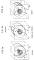
- the schematically indicated housing 10 of the washing machine carries a drum 14.
- a label holder 16 is connected to the drum 14, which is oriented concentrically to the drum axis 1 and on whose contact tracks fixed contact springs 18 act as label receivers 18.
- FIG. 1a clockwise rotation is triggered, in Fig. 1c counterclockwise rotation of the drum.
- Fig. 1b shows the braked position or the standstill, in which the drum 14 is in the loading position. In this loading position, the loading opening 12 is in the uppermost position.
- a switch 44 is provided which is in the position shown during the program run.
- the motor can be operated in a conventional manner (via further program switches (not shown)).
- a program-controlled reversing switch (not shown) also serves for reversing.
- the switch 45 can also be a program switch, which changes to the other position after a program has run. However, it can also be a switch which can be actuated from the outside of the machine or a button 44 which is actuated for the duration of the drum movement up to the loading position.
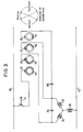
- FIG. 1 An embodiment for the switching device designed according to the invention is shown in FIG.
- the starting measure described above is carried out by a ring collector with three contact tracks 46, 48, 50, which are on a common Shaft, for example the drum shaft.
- the conductive contact tracks are closed at 46, at 48 a segment covering more than the left half of the ring collector and at 50 a segment covering more than the right half of the ring collector, both of which overlap in the upper region. All contact tracks are galvanically connected to each other. If the connection between the line 40 and the line 42 is established via the respective grinder 45 (number plate sensor 18 in FIG. 1), the induction motor with its windings 33 to 35 is always braked when the grinder 45 on the contact tracks 48 and 50 lie and carry electricity. This is the loading position.
- the power supply takes place via a button 44, by means of which the starting measure can be triggered. Similar measures, as explained above, can be taken to distinguish the program run from the special movement into the loading position.
- the loading opening 12 is to the left of the drum axis 1.
- the shortest way to the loading position is clockwise rotation.
- the label holder 16 brings two (46 and 50, FIG. 2) of its contact tracks into contact with their contact springs 45, through which the current flows via the button 44 and the windings 33 and 35 and with a phase shift via the capacitor 36 connected in parallel excited by the windings 34 and 35 and the drive motor in clockwise rotation until the drum 14 according to FIG. 1b is in the loading position, in which the three outer contact tracks 46, 48 and 50 communicate with their contact springs.
- the drum 14 is moved from its position shown in FIG Moves counterclockwise in which the two outer contact tracks communicate with their contact springs.
- Fig. 2 shows the circuit in detail using the outer three contact tracks - shown here in the loading position.
- the drum 14 can reach the loading position by running the shortest way.
- the current flows from the line 40 via the contact track 48 through the windings 34 and 35 and via the capacitor 36 phase-shifted through the winding lugs 33 and 35 to the line 42. Therefore, the drive motor remains excited in the counterclockwise rotation until the drum is in the loading position.
- the induction motor (33 to 36) becomes symmetrical, i.e. excited in phase; the machine is therefore braked in the loading position.
- an additional contact path 52 can be assigned to the contact paths 46, 48, 50 of the type shown in FIG jointly considered contact tracks 48 and 50 closes.
- This contact track 52 is connected with its grinder 45 via a capacitive series resistor 68 to the winding 33 of the induction motor when the loading opening of the drum is exactly opposite to the loading position.
- the button 44 is actuated, the circuit for the motor is then closed via the series resistor 68, which only ever moves the drum in from this opposition position one direction to the left or to the right.
- the additional contact track 52 overlaps little with the contact tracks 48 and 50 for left and right-hand rotation, so that the continuation is ensured after starting from the opposition position.
- the label holder can be designed in a variety of ways.
- the ring collector can consist of one or more printed circuit boards, the contact tracks of which are designed in the manner of a printed circuit with one or more circular tracks and differently arranged grinders.
- the drum When the button is pressed, the drum is rotated in one direction depending on its position. If the loading position is over-tightened, the corresponding other contact path gets under its grinder and initiates a counter-rotation into the loading position.
- the devices for braking the drum in the loading position may be unnecessary or may act in other ways than by in-phase excitation of the two direction windings of an induction motor.
- the switch or the button 44 can be part of a monitoring device for the closed position of the housing cover of the washing machine, in contrast to the above. Furthermore, this switch can also be inserted into the electrical circuit of the machine in such a way that other machine functions are electrically and / or mechanically excluded when it is in the position provided for turning into the loading position.
Description
Die Erfindung betrifft eine Einrichtung zum durch eine Startmaßnahme einleitbaren Bewegen der mittels eines drehrichtungsumkehrbaren Motors antreibbaren Trommel einer mantelseitig beschickbaren, programmgesteuerten Wäschebehandlungsmaschine in Beschickungsstellung mit einer Starteinrichtung, die einen mit der Trommel umlaufenden Kennzeichenträger und einen zugeordneten Kennzeichenaufnehmer enthält und die durch ihre Startmaßnahme die Trommel in Abhängigkeit von ihrer nach Programmende erreichten Stillstands-Stellung in jeweils der den kürzeren Weg in die Beschickungsstellung gewährenden Drehrichtung bis zum Erreichen der Beschickungsstellung antreibt.The invention relates to a device for moving a drum that can be driven by means of a reversible motor and a program-controlled laundry treatment machine that can be fed by a reversible motor in the loading position with a starter device that contains a license plate carrier rotating with the drum and an assigned license plate holder and that starts the drum in Depends on the standstill position reached after the end of the program in the direction of rotation which allows the shorter path to the loading position until the loading position is reached.
Eine solche Einrichtung ist aus der GB-A 20 53 977 bekannt. Die bekannte Trommel wird allerdings rein mechanisch in die Beschickungsstellung gebracht, was einen erheblichen mechanischen Aufwand für die Steuerung und die Bewegung erfordert. Dazu muß der Gehäusedeckel der Waschmaschine angehoben werden, was den Eingriff in die laufende Trommel ermöglicht. Dabei wird über ein Zugseil ein automatisches Schaltgetriebe betätigt, das über einen Kennzeichenträger und einen Kennzeichenaufnehmer im Zusammenwirken mit zwei Zahnrädern die Drehrichtung und die Position für die Beschickungsstellung bestimmt. Beim Schließen des Gehäusedeckels muß das Seil, von einer Uhrfeder getrieben, wieder auf eine Seiltromnmel aufgewickelt werden.Such a device is known from GB-A 20 53 977. However, the known drum is brought into the loading position purely mechanically, which requires considerable mechanical effort for the control and the movement. For this purpose, the housing cover of the washing machine has to be raised, which allows access to the running drum. An automatic gearbox is actuated via a traction cable, which determines the direction of rotation and the position for the loading position via a number plate holder and a number plate receiver in cooperation with two gear wheels. When closing the housing cover, the rope, driven by a clock spring, be wound up again on a rope drum.
Aus der DE-B 15 85 953 ist noch eine Vorrichtung zur Erzielung des Trommstillstandes einer Wäschetrommel in der Bedienungslage bekannt, bei der die Trommel drehfest mit einer Nockenscheibe als Kennzeichenträger verbunden ist, die einen Ruheschalter als Kennzeichenaufnehmer öffnet, sobald die Trommel in Beschickungsstellung steht. Dadurch wird der Stromkreis für den Trommelantriebsmotor unterbrochen, der zuvor von einem durch die Bewegung des Gehäusedeckels betätigten Umschalter von Waschbetrieb auf Langsambetrieb zum Drehen der Trommel in Beschickungsstellung umgeschaltet worden war. Die Trommel bleibt dann in Beschickungsstellung stehen. Zusätzlich ist noch eine von der Deckelstellung abhängige Arretiereinrichtung für die Beschickungsstellung vorgesehen.From DE-B 15 85 953 a device for achieving the drum standstill of a laundry drum in the operating position is known, in which the drum is rotatably connected to a cam disk as a number plate holder, which opens a rest switch as a number plate receiver as soon as the drum is in the loading position. As a result, the circuit for the drum drive motor is interrupted, which had previously been switched from washing operation to slow operation for rotating the drum into the loading position by a switch operated by the movement of the housing cover. The drum then remains in the loading position. In addition, a locking device depending on the lid position is provided for the loading position.
Die bekannte Vorrichtung hat einen Nachteil: Die Trommel kann sich immer nur in einer Drehrichtung in die Beschikkungsstellung bewegen, weil nur eine Wicklung des drehrichtungsumkehrbaren Motors in den dafür vorgesehenen Stromkreis eingeschaltet ist. In mindestens 50 % der Fälle dreht sich daher die Trommel um mehr als eine halbe Umdrehung und benötigt dazu eine lange Zeit. Für die Dauer dieser Zeit muß die Bedienungsperson das Erreichen der Beschickungsstellung abwarten. Ungeduldige Bedienungspersonen werden allerdings während des Laufs der Trommel bereits versuchen, den Gehäusedeckel gegen die vorläufige Sperre ganz zu öffnen, und belasten dadurch die machanischen Einrichtungen (Deckel, Deckellagerung, feste und bewegliche Teile der Arretiereinrichtung), deren Festigkeit darauf bemessen sein muß.The known device has a disadvantage: the drum can only ever move into the charging position in one direction of rotation because only one winding of the reversible motor is switched on in the circuit provided for this purpose. In at least 50% of the cases, the drum rotates more than half a turn and takes a long time to do this. The operator must wait for the loading position to be reached for the duration of this time. Impatient operators, however, will already try to open the housing cover fully against the temporary lock while the drum is running, thereby putting a strain on the mechanical equipment (cover, cover storage, fixed and moving parts of the locking device), the strength of which must be dimensioned accordingly.
Die US-A 2 479 153 offenbart eine Waschmaschine mit einem mit der Trommel starr verbundenen Kreissegment, welches mit einem Hebel zusammenwirkt, der den Antriebsmotor umpolt. Nach Auslösen des Stopsignals bzw. der Schaltmaßnahme läuft die Trommel immer im Vorwärtslauf in den für die Beschikkungsstellung vorgesehenen Anhaltebereich ein. Gegebenenfalls notwendige Drehrichtungsänderungen wegen Überfahren der Beschickungsstellung werden während der Bewegung der Trommel indiziert, wobei bei sehr großer Trägheit der Trommel eine zusätzliche Umdrehung gefahren wird. Somit ergeben sich die gleichen Nachteile wie bei der DE-A-1 585 953.US-A 2 479 153 discloses a washing machine with a circular segment rigidly connected to the drum, which cooperates with a lever which reverses the polarity of the drive motor. After triggering the stop signal or the switching measure, the drum always runs forward in the stopping area provided for the charging position. Any necessary changes in the direction of rotation due to the loading position being overrun are indicated during the movement of the drum, with an additional rotation being carried out when the drum is very inert. This results in the same disadvantages as in DE-A-1 585 953.
Ausgehend von einer Einrichtung der eingangs genannten Art liegt der Erfindung die Aufgabe zugrunde, die Trommel einer Wasch- und/oder Trockenmaschine nach Ablauf des Behandlungsprogramms durch einfache Mittel über den kürzesten Weg in die Beschickungsstellung zu befördern.On the basis of a device of the type mentioned at the outset, the object of the invention is to convey the drum of a washing and / or drying machine to the loading position by simple means after the treatment program has ended, using the shortest possible route.
Diese Aufgabe wird erfindungsgemäß dadurch gelöst, daß der Kennzeichenträger eine Anordnung von drei drehfest mit der Trommel verbundenen Kontaktbahnen eines oder mehrerer Ringkollektoren enthält, von denen die eine Kontaktbahn in sich geschlossen und die beiden anderen Kontaktbahnen segmentartig geformt und gegeneinander um 180° sind und daß die geschlossene Kontaktbahn in Abhängigkeit von ihrer Drehstellung über Bahnschleifer entweder mit der einen oder mit der anderen segmentartigen Kontaktbahn in einen Serienstromkreis von Reversierwicklungen des Trommelantriebsmotors geschaltet ist. Dadurch wird erreicht, daß die Trommel immer über den kürzesten Weg und damit in kürzestmöglicher Zeit in die Beschickungsstellung gelangt, ohne die Geduld der Bedienungsperson übermäßig zu strapazieren. Durch die vorstehende Startmaßnahme kann die Trommel mit reduzierter Drehzahl oder mit Waschdrehzahl angetrieben werden. Durch die erfindungsgemäßen Maßnahmen ist es nicht erforderlich, die mechanischen Einrichtungen auf ungedulidge Handhabung durch Bedienungspersonen auszulegen. Hieraus ergibt sich außerdem ein besonders geringer Aufwand für die Mittel zur Lösung der gestellten Aufgabe. Außerhalb des Laugenbehälters einer Waschmaschine befindet sich beispielsweise die Riemenscheibe für den Antrieb der Wäschetrommel, die drehfest miteinander verbunden sind, so daß die Riemenscheibe ein geeigneter Ort für die Anbringung eines Kennzeichenträgers ist.This object is achieved in that the number plate holder contains an arrangement of three non-rotatably connected contact tracks of the drum of one or more ring collectors, of which one contact track is self-contained and the other two contact tracks are segment-shaped and 180 ° against each other and that closed contact path is connected depending on its rotational position via path grinder either with one or with the other segment-like contact path in a series circuit of reversing windings of the drum drive motor. The result of this is that the drum always reaches the loading position by the shortest route and thus in the shortest possible time, without unduly stressing the operator's patience. Due to the above starting measure, the drum can be reduced Speed or with washing speed. As a result of the measures according to the invention, it is not necessary to design the mechanical devices for unpatented handling by operators. This also results in a particularly low outlay for the means for solving the task. Outside the tub of a washing machine is, for example, the pulley for driving the laundry drum, which are rotatably connected to each other, so that the pulley is a suitable place for attaching a license plate.
In besonders vorteilhafter Weise ist die Trommel oder ihr Antriebsmotor in Beschickungsstellung abbremsbar ausgebildet. Dadurch kann auch bei ungünstiger Verteilung der Wäsche in der Trommel die einmal erreichte Beschickungsstellung sicher eingehalten werden.In a particularly advantageous manner, the drum or its drive motor can be braked in the loading position. As a result, the loading position once reached can be reliably maintained even when the laundry is distributed unfavorably in the drum.
Eine besonders einfache und wirksame Ausbildung der Erfindung für die gebremste Einhaltung der Beschickungsstellung ergibt sich bei einer weitergebildeten Einrichtung der Erfindung mit einem zwei- oder dreisträngigen Einphasen-Induktionsmotor dadurch, daß die drehrichtungsbestimmenden Stränge des Motors während der Bremsung phasengleich erregbar sind.A particularly simple and effective embodiment of the invention for the braked compliance with the loading position results in a further development of the invention with a two- or three-strand single-phase induction motor in that the direction-determining strands of the motor can be excited in phase during braking.
Die Startmaßnahme kann in einfacher Weise durch Betätigung einer Taste auslösbar sein, damit die Bedienungsperson selbst entscheiden kann, ob die Trommel in die Beschikkungsstellung fahren muß oder nicht.The starting measure can be triggered in a simple manner by pressing a button, so that the operator can decide for himself whether the drum must move into the loading position or not.
In Fortbildung dieser Ausgestaltung kann die Taste der Dekkelschalter einer Verriegelungseinrichtung für den Gehäusedeckel sein. Dann genügt das Anheben des Deckels, um die Trommel in die Beschickungsstellung fahren zu können. Allerdings wird es hierzu empfehlenswert sein, die Trommel während dieser Betriebsphase mit einer verminderten Drehzahl anzutreiben, um die Gefahr für die Bedienungsperson zu verringern, durch-eine Berührung mit der drehenden Trommel Schaden zu nehmen.In a further development of this embodiment, the button of the lid switch of a locking device for the housing cover be. Then it is sufficient to lift the lid to be able to move the drum into the loading position. However, it will be advisable to drive the drum at a reduced speed during this operating phase in order to reduce the risk for the operator of being damaged by contact with the rotating drum.
In einer anderen Ausbildungsvariante ist die Startmaßnahme nur über einen Schalter im Programmsteuergerät auslösbar. Dies kann im Zusammenhang mit einer vorstehend beschriebenen Taste stehen oder obligatorisch jedem Behandlungsprogramm am Ende zugeordnet sein. Dabei sollte die Startmaßnahme bei einem Programm ohne Schleuderabschnitt nur nach Spülende bzw. bei einem Programm mit Schleuderabschnitt nur auslösbar sein, wenn der Schleuderauslauf beendet ist.In another training variant, the start measure can only be triggered by a switch in the program control unit. This can be related to a button described above or it can be assigned to each treatment program at the end. In the case of a program without a spin section, the start measure should only be able to be triggered after the end of the rinse or, in the case of a program with a spin section, only when the spin cycle has ended.
Es kann zweckmäßig sein, wenn die Erfindung derart ausgebildet ist, daß die Taste bei Betätigung andere Programmfunktionen ausblendet. Dadurch kann gesichert werden, daß kein Schaltfehler in der Programmsteuereinrichtung beim Betätigen der Taste noch irgendeine andere Maschinenfunktion auslöst, z.B. Wasserzulauf, Trommeldrehung, Schleuderlauf. Bei einer Trommeldrehstellung, bei der die Beschickungsöffnung der Beschickungsstellung genau gegenüberliegt, könnte im Falle der Ausstattung des Kennzeichnungsträgers mit Kontaktbahnen eine unsichere Schaltstellung entstehen, aus der die Trommel nicht sicher anlaufen kann. Um dies zu vermeiden, ist die Erfindung dadurch vorteilhaft weitergebildet, daß im der Beschickungsstellung gegenüberliegenden Bereich des Kennzeichenträgers ein weiteres Kennzeichen angeordnet ist, dessen Startmaßnahme zum Anlaufen des Motors immer nur in einer Drehrichtung führt. Nach Verlassen dieses weiteren Kennzeichens bei der Drehung des Kennzeichenträgers aus dieser unsicheren Schaltstellung heraus wird dann eine der segmentartig geformten Kontaktbahnen die weitere Drehung des Antriebsmotors in der jeweils zugeordneten Drehrichtung übernehmen. Entsprechend der Ausgestaltung des Kennzeichenträgers mit Kontaktbahnen kann das weitere Kennzeichen eine kurze, segmentartige Kontaktbahn sein und mit der geschlossenen Kontaktbahn während einer Trommelstellung, bei der die Beschickungsöffnung der Beschickungsstellung gegenüber steht, in einen Serienstromkreis mit einer bestimmten der beiden Reversierwicklungen des Trommelantriebsmotors geschaltet sein.It may be appropriate if the invention is designed such that the key hides other program functions when actuated. This ensures that no switching error in the program control device triggers any other machine function when the button is pressed, for example water supply, drum rotation, spin cycle. In the case of a drum rotation position in which the loading opening is exactly opposite the loading position, an unsafe switching position could arise if the label carrier is equipped with contact tracks, from which the drum cannot start safely. In order to avoid this, the invention is advantageously further developed in that a further number plate is arranged in the area of the number plate holder opposite the loading position, the starting measure of which only leads to the motor starting in one direction of rotation. After leaving this further When the number plate carrier rotates out of this unsafe switching position, one of the segment-shaped contact tracks will then take over the further rotation of the drive motor in the respectively assigned direction of rotation. According to the design of the label holder with contact tracks, the further label can be a short, segment-like contact track and can be connected with the closed contact track during a drum position, in which the loading opening is opposite the loading position, into a series circuit with a specific one of the two reversing windings of the drum drive motor.
Ausführungsbeispiele der Erfindung sollen mit Bezug auf die beiliegenden Zeichnungen nachstehend näher erläutert werden. Diese zeigen in
- Fig. 1
- eine Waschmaschine mit Kennzeichenträger als Teil einer Schalteinrichtung zum Bewegen der Waschmaschinen-Trommel in Beschickungsstellung in drei unterschiedlichen Trommelpositionen,
- Fig. 2
- eine Prinzipschaltung der Schalteinrichtung mit Ringkollektoren gemäß Fig. 1,
- Fig. 3
- eine Verbesserung der Schaltung nach Fig. 2 mit Anlaufeinrichtung.
- Fig. 1
- a washing machine with license plate holder as part of a switching device for moving the washing machine drum in the loading position in three different drum positions,
- Fig. 2
- 2 shows a basic circuit of the switching device with ring collectors according to FIG. 1,
- Fig. 3
- an improvement of the circuit of FIG. 2 with starting device.
Das schematisch angedeutete Gehäuse 10 der Waschmaschine trägt eine Trommel 14. Mit der Trommel 14 ist zur Kennzeichnung für die Stellung der Trommel ein konzentrisch zur Trommelachse 1 orientierter Kennzeichenträger 16 verbunden, an deren Kontaktbahnen feste Kontaktfedern 18 als Kennzeichenaufnehmer 18 angreifen.The schematically indicated
In Fig. 1a wird Rechtslauf, in Fig. 1c Linkslauf der Trommel ausgelöst. Fig. 1b zeigt die abgebremste Stellung oder den Stillstand, bei der die Trommel 14 in Beschickungsstellung steht. In dieser Beschickungsstellung befindet sich die Beschickungsöffnung 12 in der obersten Lage.In Fig. 1a clockwise rotation is triggered, in Fig. 1c counterclockwise rotation of the drum. Fig. 1b shows the braked position or the standstill, in which the
In den Schaltbildern der Fig. 2 und 3 ist ein Schalter 44 vorgesehen, der während des Programmlaufs in der gezeichneten Lage steht. Dabei kann der Motor in üblicher Weise (über weitere nicht dargestellte Programmschalter) programmgesteuert betätigt werden. Zum Reversieren dient dabei ein ebenfalls programmgesteuerter Reversierschalter (nicht dargestellt).In the circuit diagrams of FIGS. 2 and 3, a switch 44 is provided which is in the position shown during the program run. The motor can be operated in a conventional manner (via further program switches (not shown)). A program-controlled reversing switch (not shown) also serves for reversing.
Der Schalter 45 kann ebenfalls ein Programmschalter sein, der nach Ablaufen eines Programms in die andere Lage wechselt. Er kann aber auch ein von der Maschinen-Außenseite her betätigbarer Schalter oder eine Taste 44 sein, die für die Dauer der Trommelbewegung bis in die Beschickungsstellung betätigt wird.The
Eine Ausführungsform für die erfindungsgemäß gestaltete Schalteinrichtung ist in Fig.2 gezeigt. Hier erfolgt die oben beschriebene Startmaßnahme durch einen Ringkollektor mit drei Kontaktbahnen 46, 48, 50, die auf einer gemeinsamen Welle, z.B. der Trommelwelle, sitzen. Die leitenden Kontaktbahnen sind bei 46 geschlossen ringförmig, bei 48 ein mehr als die linke Hälfte des Ringkollektors überdekkendes Segment und bei 50 ein mehr als die rechte Hälfte des Ringkollektors überdeckendes Segment, die sich im oberen Bereich beide überlappen. Alle Kontaktbahnen sind miteinander galvanisch verbunden. Ist über den jeweiligen Schleifer 45 (Kennzeichenaufnehmer 18 in Fig.1) die Verbindung zwischen der Leitung 40 und der Leitung 42 hergestellt, so wird der Induktionsmotor mit seinen Wicklungen 33 bis 35 immer dann abgebremst, wenn die Schleifer 45 an den Kontaktbahnen 48 und 50 liegen und Strom führen. Dies ist die Beschickungsstellung.An embodiment for the switching device designed according to the invention is shown in FIG. Here, the starting measure described above is carried out by a ring collector with three
Die Stromzuführung erfolgt über eine Taste 44, durch welche die Startmaßnahme ausgelöst werden kann. Zur Unterscheidung des Programmlaufs von der Sonderbewegung in die Beschikkungsstellung können ähnliche Maßnahmen, wie oben erläutert, getroffen werden.The power supply takes place via a button 44, by means of which the starting measure can be triggered. Similar measures, as explained above, can be taken to distinguish the program run from the special movement into the loading position.
In Fig. 1a befindet sich die Beschickungsöffnung 12 links von der Trommelachse 1. Der kürzeste Weg zur Beschickungsstellung ist der Rechtslauf. Der Kennzeichenträger 16 bringt in dieser Position zwei (46 und 50, Fig.2) seiner Kontaktbahnen mit ihren Kontaktfedern 45 in Kontakt, durch die der Strom über die Taste 44 und die Wicklungen 33 und 35 fließt sowie mit Phasendrehung über den parallel geschalteten Kondensator 36 durch die Wicklungen 34 und 35 und den Antriebsmotor solange im Rechtslauf erregt, bis sich die Trommel 14 gemäß Fig.1b in Beschickungsstellung befindet, in der die drei äußeren Kontaktbahnen 46, 48 und 50 mit ihren Kontaktfedern kommunizieren. Entsprechend wird die Trommel 14 aus ihrer in Fig.1c gezeigten Stellung im Linkslauf bewegt, in dem die beiden äußeren Kontaktbahnen mit ihren Kontaktfedern kommunizieren. Fig.2 zeigt die Schaltung im einzelnen anhand der äußeren drei Kontaktbahnen - hier in Beschickungsstellung dargestellt.In Fig. 1a, the
Wenn die Beschickungsöffnung 12 gemäß Fig.1c rechts von der Trommelachse 1 steht, kann die Trommel 14 durch Linkslauf auf dem kürzesten Weg in Beschickungsstellung gelangen. Dabei fließt der Strom von der Leitung 40 über die Kontaktbahn 48 durch die Wicklungen 34 und 35 sowie über den Kondensator 36 phasenverschobewn durch die Wicklugnen 33 und 35 zur Leitung 42. Daher bleibt der Antriebsmotor im Linkslauf solange erregt, bis die Trommel in Beschickungsstellung steht.If the
In Beschickungsstellung (Fig. 1b) wird der Induktionsmotor (33 bis 36) symmetrisch, d.h. phasengleich erregt; die Maschine ist daher in Beschickungsstellung abgebremst.In the loading position (Fig. 1b), the induction motor (33 to 36) becomes symmetrical, i.e. excited in phase; the machine is therefore braked in the loading position.
Um ein unsicheres Anlaufverhalten aus einer Trommelstellung zu vermeiden, bei der die Beschickungsöffnung der Beschikkungsstellung genau gegenüberliegt, kann gemäß Fig. 3 den Kontaktbahnen 46, 48, 50 der in Fig. 2 gezeigten Art eine zusätzliche Kontaktbahn 52 beigeordnet werden, welche die Lücke bei den gemeinsam betrachteten Kontaktbahnen 48 und 50 schließt. Diese Kontaktbahn 52 ist mit ihrem Schleifer 45 über einen kapazitiven Vorwiderstand 68 an die Wicklung 33 des Induktionsmotors angeschlossen, wenn die Beschikkungsöffnung der Trommel der Beschickungsstellung genau gegenübersteht. Bei betätigter Taste 44 ist dann der Stromkreis für den Motor über den Vorwiderstand 68 geschlossen, der die Trommel aus dieser Oppositionsstellung immer nur in einer Drehrichtung links- oder rechtsherum dreht. Die zusätzliche Kontaktbahn 52 überlappt wenig mit den Kontaktbahnen 48 und 50 für den Links- und Rechtslauf, so daß der Weiterlauf nach Anlauf aus der Oppositionsstellung gesichert ist.In order to avoid unsafe start-up behavior from a drum position in which the loading opening is exactly opposite the loading position, according to FIG. 3 an
Der Kennzeichenträger kann auf vielfältige Weise ausgebildet sein. So kann der Ringkollektor beispielsweise aus einer oder mehreren Leiterplatten bestehen, deren Kontaktbahnen nach Art einer gedruckten Schaltung mit einem oder mehreren Kreisbahnen und unterschiedlich angeordneten Schleifern ausgeführt sind.The label holder can be designed in a variety of ways. For example, the ring collector can consist of one or more printed circuit boards, the contact tracks of which are designed in the manner of a printed circuit with one or more circular tracks and differently arranged grinders.
Beim Betätigen der Taste wird die Trommel abhängig von ihrer Lage in einer Richtung gedreht. Sollte die Beschikkungsstellung überdreht werden, so gelangt die entsprechend andere Kontaktbahn unter ihren Schleifer und leitet ein Gegendrehen in die Beschickungsstellung ein. Die Einrichtungen zum Bremsen der Trommel in der Beschickungsstellung sind möglicherweise entbehrlich oder können auf andere Weise wirken als durch phasengleiches Erregen der beiden Richtungswicklungen eines Induktionsmotors.When the button is pressed, the drum is rotated in one direction depending on its position. If the loading position is over-tightened, the corresponding other contact path gets under its grinder and initiates a counter-rotation into the loading position. The devices for braking the drum in the loading position may be unnecessary or may act in other ways than by in-phase excitation of the two direction windings of an induction motor.
Der Schalter bzw. die Taste 44 können anders als oben angegeben Bestandteil einer Überwachungseinrichtung für die Schließstellung des Gehäusedeckels der Waschmaschine sein. Ferner kann dieser Schalter auch so in die elektrische Schaltung der Maschine eingefügt sein, daß bei seiner zum Drehen in die Beschickungsstellung vorgesehenen Lage andere Maschinenfunktionen elektrisch und/ oder mechanisch ausgeschlossen werden.The switch or the button 44 can be part of a monitoring device for the closed position of the housing cover of the washing machine, in contrast to the above. Furthermore, this switch can also be inserted into the electrical circuit of the machine in such a way that other machine functions are electrically and / or mechanically excluded when it is in the position provided for turning into the loading position.
Claims (11)
- Equipment for the movement, which can be initiated by a starting measure, into a loading position of a drum, which is drivable by means of a motor reversible in rotational direction, of a program-controlled laundry treatment machine loadable at the casing side, comprising a starting device which contains a mark carrier turning with the drum and an associated mark pick-up and which by its starting measure drives the drum (14), in dependence on the stopped position thereof attained after program end, in the respective rotational direction offering the shorter path into the loading position until the loading position is reached, characterised thereby that the mark carrier (16) comprises an arrangement (18) of three contact tracks (46, 48, 50), which are connected to the drum (14) to be secure against rotation relative thereto, of one or more ring collectors, of which the one contact track (46) is closed in itself and the two other contact tracks (48and 50) are formed to be segment-shaped and arranged to be offset relative to one another by 180° and that the closed contact track (46) is connected in dependence on its rotational position and by way of a track wiper (45) either with the one or with the other segment-shaped contact track (48 or 50) into a series circuit of reversing windings (33 or 34) of the drum drive motor.
- Equipment according to claim 1, characterised thereby that the drum (14) or its drive motor is constructed to be brakable into the loading position.
- Equipment according to claim 1 or 2 with a two or three rod single phase induction motor, characterised thereby that the rods (33, 34), which determine rotational direction, of the motor are excitable in same phase during the braking.
- Equipment according to one of claims 1 to 3 with a pulley connected with the drum, characterised thereby that the mark carrier is mounted between the drum and the pulley.
- Equipment according to one of claims 1 to 4, characterised thereby that the starting measure can be triggered by actuation of a button (44).
- Equipment according to claim 5, characterised thereby that the button (44) is the cover switch of a locking equipment for the housing cover.
- Equipment according to claim 1, 2, 5 or 6, characterised thereby that the starting measure can be triggered only by way of a switch in the program control apparatus.
- Equipment according to claim 7, characterised thereby that in the case of a program without a spinning section the starting measure can be triggered only after the end of rinsing or in the case of a program with a spinning section can be triggered only when the spinning rundown has ended.
- Equipment according to one of claims 5 to 8, characterised thereby that the button (44) is masked out on actuation of other program functions.
- Equipment according to one of the preceding claims, characterised thereby, that a further mark (52), the starting measure of which leads to starting of the motor always only in one rotational direction, is arranged in the region of the mark carrier (46, 48, 50) opposite the loading position.
- Equipment according to claim 17, characterised thereby that the further mark is a short segment-shaped contact track (ring collector 52) and is connected together with the closed contact track (ring collector 46) into a series circuit with a specific reversing winding (33) of the drum drive motor during a drum setting in which the loading opening (12) stands in the loading position.
Applications Claiming Priority (2)
| Application Number | Priority Date | Filing Date | Title |
|---|---|---|---|
| DE19863623059 DE3623059A1 (en) | 1986-07-09 | 1986-07-09 | DEVICE FOR MOVING THE DRUM OF A LAUNDRY TREATMENT MACHINE IN THE LOADING POSITION |
| DE3623059 | 1986-07-09 |
Publications (4)
| Publication Number | Publication Date |
|---|---|
| EP0253250A2 EP0253250A2 (en) | 1988-01-20 |
| EP0253250A3 EP0253250A3 (en) | 1988-07-20 |
| EP0253250B1 EP0253250B1 (en) | 1992-05-13 |
| EP0253250B2 true EP0253250B2 (en) | 1996-05-01 |
Family
ID=6304741
Family Applications (1)
| Application Number | Title | Priority Date | Filing Date |
|---|---|---|---|
| EP87109666A Expired - Lifetime EP0253250B2 (en) | 1986-07-09 | 1987-07-04 | Device for positioning the drum of a washing machine |
Country Status (3)
| Country | Link |
|---|---|
| EP (1) | EP0253250B2 (en) |
| DE (2) | DE3623059A1 (en) |
| ES (1) | ES2031475T5 (en) |
Families Citing this family (9)
| Publication number | Priority date | Publication date | Assignee | Title |
|---|---|---|---|---|
| DE3728940C2 (en) * | 1987-08-29 | 1998-10-01 | Miele & Cie | Mantle-loading washer dryer |
| ES2026381A6 (en) * | 1989-11-28 | 1992-04-16 | Bosch Siemens Hausgeraete | Drum washing machine with drum drive motor - in which rotor is coupled to tachogenerator |
| JP2834855B2 (en) * | 1990-06-26 | 1998-12-14 | 三洋電機株式会社 | Drum type washing machine |
| DE4109541C2 (en) * | 1991-03-22 | 1995-08-17 | Bosch Siemens Hausgeraete | Device for fastening a signal transmitter for the laundry drum of a household washing machine |
| US5448900A (en) * | 1994-05-02 | 1995-09-12 | Whirlpool Corporation | System for automatically opening basket doors of a top loading horizontal axis automatic washer |
| US5398528A (en) * | 1994-05-02 | 1995-03-21 | Whirlpool Corporation | Pulley system for automatic washer |
| US5469593A (en) * | 1994-05-02 | 1995-11-28 | Whirlpool Corporation | Basket positioning system for a top loading horizontal axis automatic washer |
| ES2202999T5 (en) * | 1999-12-23 | 2008-12-16 | DIEHL AKO STIFTUNG & CO. KG | PROCEDURE FOR POSITIONING A WASHING DRUM OF A WASHER IN AN OBJECTIVE POSITION. |
| CN112779719A (en) * | 2019-11-01 | 2021-05-11 | 佛山市云米电器科技有限公司 | Washing machine deceleration method and system, storage medium and washing machine |
Citations (3)
| Publication number | Priority date | Publication date | Assignee | Title |
|---|---|---|---|---|
| US2479153A (en) † | 1944-04-27 | 1949-08-16 | American Machine & Metals Inc | Reversing and stop control for electric motors |
| DE1585953A1 (en) † | 1963-05-16 | 1970-07-16 | Siemens Elektrogeraete Gmbh | Device for bringing the drum to a standstill of a jacket-loaded laundry treatment machine in the operating position |
| GB2053977A (en) † | 1979-06-01 | 1981-02-11 | Hoover Ltd | Washing machines |
Family Cites Families (2)
| Publication number | Priority date | Publication date | Assignee | Title |
|---|---|---|---|---|
| FR2296719A1 (en) * | 1974-12-30 | 1976-07-30 | Chalectro Cie Machines Laver L | Washing machine with rotary drum stop control - to ensure drum opening is arrested in alignment with machine door. |
| FR2300837A2 (en) * | 1975-02-11 | 1976-09-10 | Chalectro Machines | Washing machine with peripheral access drum - has switch to short circuit motor windings when access aligns with door |
-
1986
- 1986-07-09 DE DE19863623059 patent/DE3623059A1/en not_active Withdrawn
-
1987
- 1987-07-04 EP EP87109666A patent/EP0253250B2/en not_active Expired - Lifetime
- 1987-07-04 DE DE8787109666T patent/DE3778987D1/en not_active Expired - Lifetime
- 1987-07-04 ES ES87109666T patent/ES2031475T5/en not_active Expired - Lifetime
Patent Citations (4)
| Publication number | Priority date | Publication date | Assignee | Title |
|---|---|---|---|---|
| US2479153A (en) † | 1944-04-27 | 1949-08-16 | American Machine & Metals Inc | Reversing and stop control for electric motors |
| DE1585953A1 (en) † | 1963-05-16 | 1970-07-16 | Siemens Elektrogeraete Gmbh | Device for bringing the drum to a standstill of a jacket-loaded laundry treatment machine in the operating position |
| DE1585953B2 (en) † | 1963-05-16 | 1972-01-27 | Siemens Electrogerate GmbH, 1000 Berlin u 8000 München | DEVICE FOR ACHIEVING THE DRUM STANDSTILL OF A CLOTHED LAUNDRY MACHINE IN THE OPERATING POSITION |
| GB2053977A (en) † | 1979-06-01 | 1981-02-11 | Hoover Ltd | Washing machines |
Also Published As
| Publication number | Publication date |
|---|---|
| ES2031475T5 (en) | 1996-07-16 |
| DE3778987D1 (en) | 1992-06-17 |
| ES2031475T3 (en) | 1992-12-16 |
| EP0253250A3 (en) | 1988-07-20 |
| DE3623059A1 (en) | 1988-01-21 |
| EP0253250A2 (en) | 1988-01-20 |
| EP0253250B1 (en) | 1992-05-13 |
Similar Documents
| Publication | Publication Date | Title |
|---|---|---|
| EP0253250B2 (en) | Device for positioning the drum of a washing machine | |
| DE2219585A1 (en) | Device for feeding a thread from a supply to a textile machine | |
| DE2844134A1 (en) | PLAY MACHINE | |
| DE19750934C2 (en) | Washing machine with a drive system | |
| DE2928507C2 (en) | Safety locking device for foldable or removable protective cover parts of machines | |
| DE2311956A1 (en) | DEVICE FOR ACHIEVING THE DRUM STANDSTILL OF A CASE LOADABLE DRUM WASHING MACHINE IN THE OPERATING POSITION | |
| DE3543213C2 (en) | ||
| DE3029338C2 (en) | Device for the positioned stopping of the arm shaft of a sewing machine | |
| WO1999010584A1 (en) | Washing machine | |
| DE2834579C2 (en) | engine | |
| EP0823503A2 (en) | Top loading drum washing machine | |
| DE2126445C (en) | Control device for a circulation register driven by an electric motor | |
| DE443563C (en) | Traction sheave elevator with automatic fine adjustment | |
| DE2460315C3 (en) | Switching arrangement for reversing the direction of rotation of an electric motor driving the drum of a drum dryer | |
| DE487174C (en) | Control for green malt turner | |
| DE359524C (en) | Control device for electric elevators | |
| DE10043812B4 (en) | Method and device for controlling the travel speed of a unit of a printing material processing machine and the like | |
| DE2163469A1 (en) | RIBBON TRANSPORT DEVICE ON PRINTING OFFICE MACHINES OR THE LIKE | |
| DE156231C (en) | ||
| DE2214635C3 (en) | Jacket loadable drum washing machine | |
| DE439422C (en) | Electric switch, which is driven by a rotating machine part when the direction of rotation is reversed by means of friction | |
| DE1536741C (en) | Control device for a circulation register driven by an electric motor | |
| DE1760540C3 (en) | Program control device for a washing machine | |
| DE2444136C3 (en) | Tape device | |
| DE105486C (en) |
Legal Events
| Date | Code | Title | Description |
|---|---|---|---|
| PUAI | Public reference made under article 153(3) epc to a published international application that has entered the european phase |
Free format text: ORIGINAL CODE: 0009012 |
|
| AK | Designated contracting states |
Kind code of ref document: A2 Designated state(s): DE ES FR IT |
|
| PUAL | Search report despatched |
Free format text: ORIGINAL CODE: 0009013 |
|
| AK | Designated contracting states |
Kind code of ref document: A3 Designated state(s): DE ES FR IT |
|
| 17P | Request for examination filed |
Effective date: 19880607 |
|
| 17Q | First examination report despatched |
Effective date: 19900711 |
|
| GRAA | (expected) grant |
Free format text: ORIGINAL CODE: 0009210 |
|
| AK | Designated contracting states |
Kind code of ref document: B1 Designated state(s): DE ES FR IT |
|
| PG25 | Lapsed in a contracting state [announced via postgrant information from national office to epo] |
Ref country code: FR Effective date: 19920513 |
|
| ET | Fr: translation filed | ||
| RAP2 | Party data changed (patent owner data changed or rights of a patent transferred) |
Owner name: BOSCH-SIEMENS HAUSGERAETE GMBH |
|
| REF | Corresponds to: |
Ref document number: 3778987 Country of ref document: DE Date of ref document: 19920617 |
|
| ITF | It: translation for a ep patent filed |
Owner name: STUDIO JAUMANN |
|
| PLBI | Opposition filed |
Free format text: ORIGINAL CODE: 0009260 |
|
| 26 | Opposition filed |
Opponent name: MIELE & CIE. GMBH & CO Effective date: 19930212 |
|
| RAP4 | Party data changed (patent owner data changed or rights of a patent transferred) |
Owner name: BOSCH-SIEMENS HAUSGERAETE GMBH |
|
| PGFP | Annual fee paid to national office [announced via postgrant information from national office to epo] |
Ref country code: ES Payment date: 19950623 Year of fee payment: 9 |
|
| PGFP | Annual fee paid to national office [announced via postgrant information from national office to epo] |
Ref country code: DE Payment date: 19950825 Year of fee payment: 9 |
|
| PLAW | Interlocutory decision in opposition |
Free format text: ORIGINAL CODE: EPIDOS IDOP |
|
| PUAH | Patent maintained in amended form |
Free format text: ORIGINAL CODE: 0009272 |
|
| STAA | Information on the status of an ep patent application or granted ep patent |
Free format text: STATUS: PATENT MAINTAINED AS AMENDED |
|
| 27A | Patent maintained in amended form |
Effective date: 19960501 |
|
| AK | Designated contracting states |
Kind code of ref document: B2 Designated state(s): DE ES FR IT |
|
| REG | Reference to a national code |
Ref country code: ES Ref legal event code: BA2A Ref document number: 2031475 Country of ref document: ES Kind code of ref document: T5 |
|
| PGFP | Annual fee paid to national office [announced via postgrant information from national office to epo] |
Ref country code: FR Payment date: 19960613 Year of fee payment: 10 |
|
| PG25 | Lapsed in a contracting state [announced via postgrant information from national office to epo] |
Ref country code: ES Free format text: LAPSE BECAUSE OF EXPIRATION OF PROTECTION Effective date: 19960705 |
|
| EN | Fr: translation not filed | ||
| PG25 | Lapsed in a contracting state [announced via postgrant information from national office to epo] |
Ref country code: DE Effective date: 19970402 |
|
| REG | Reference to a national code |
Ref country code: ES Ref legal event code: FD2A Effective date: 19990601 |
|
| PG25 | Lapsed in a contracting state [announced via postgrant information from national office to epo] |
Ref country code: IT Free format text: LAPSE BECAUSE OF NON-PAYMENT OF DUE FEES;WARNING: LAPSES OF ITALIAN PATENTS WITH EFFECTIVE DATE BEFORE 2007 MAY HAVE OCCURRED AT ANY TIME BEFORE 2007. THE CORRECT EFFECTIVE DATE MAY BE DIFFERENT FROM THE ONE RECORDED. Effective date: 20050704 |