EP0252802B1 - Holzbearbeitungsmaschine zur Fertigung von Fensterrahmen - Google Patents
Holzbearbeitungsmaschine zur Fertigung von Fensterrahmen Download PDFInfo
- Publication number
- EP0252802B1 EP0252802B1 EP87401467A EP87401467A EP0252802B1 EP 0252802 B1 EP0252802 B1 EP 0252802B1 EP 87401467 A EP87401467 A EP 87401467A EP 87401467 A EP87401467 A EP 87401467A EP 0252802 B1 EP0252802 B1 EP 0252802B1
- Authority
- EP
- European Patent Office
- Prior art keywords
- carriage
- guides
- tool
- parallel
- piece
- Prior art date
- Legal status (The legal status is an assumption and is not a legal conclusion. Google has not performed a legal analysis and makes no representation as to the accuracy of the status listed.)
- Expired
Links
- 238000004519 manufacturing process Methods 0.000 title 1
- 238000003754 machining Methods 0.000 claims abstract description 12
- 239000002023 wood Substances 0.000 claims abstract description 11
- 238000006073 displacement reaction Methods 0.000 claims abstract description 5
- 230000007246 mechanism Effects 0.000 description 2
- 230000004913 activation Effects 0.000 description 1
- 230000004888 barrier function Effects 0.000 description 1
- 239000000470 constituent Substances 0.000 description 1
- 235000021183 entrée Nutrition 0.000 description 1
- 238000012432 intermediate storage Methods 0.000 description 1
- 230000009467 reduction Effects 0.000 description 1
- 239000011435 rock Substances 0.000 description 1
- 238000000926 separation method Methods 0.000 description 1
- 238000007493 shaping process Methods 0.000 description 1
Images


Classifications
-
- B—PERFORMING OPERATIONS; TRANSPORTING
- B23—MACHINE TOOLS; METAL-WORKING NOT OTHERWISE PROVIDED FOR
- B23Q—DETAILS, COMPONENTS, OR ACCESSORIES FOR MACHINE TOOLS, e.g. ARRANGEMENTS FOR COPYING OR CONTROLLING; MACHINE TOOLS IN GENERAL CHARACTERISED BY THE CONSTRUCTION OF PARTICULAR DETAILS OR COMPONENTS; COMBINATIONS OR ASSOCIATIONS OF METAL-WORKING MACHINES, NOT DIRECTED TO A PARTICULAR RESULT
- B23Q9/00—Arrangements for supporting or guiding portable metal-working machines or apparatus
- B23Q9/0064—Portable machines cooperating with guide means not supported by the workpiece during working
- B23Q9/0078—Portable machines cooperating with guide means not supported by the workpiece during working the guide means being fixed to a support
-
- B—PERFORMING OPERATIONS; TRANSPORTING
- B23—MACHINE TOOLS; METAL-WORKING NOT OTHERWISE PROVIDED FOR
- B23Q—DETAILS, COMPONENTS, OR ACCESSORIES FOR MACHINE TOOLS, e.g. ARRANGEMENTS FOR COPYING OR CONTROLLING; MACHINE TOOLS IN GENERAL CHARACTERISED BY THE CONSTRUCTION OF PARTICULAR DETAILS OR COMPONENTS; COMBINATIONS OR ASSOCIATIONS OF METAL-WORKING MACHINES, NOT DIRECTED TO A PARTICULAR RESULT
- B23Q1/00—Members which are comprised in the general build-up of a form of machine, particularly relatively large fixed members
- B23Q1/25—Movable or adjustable work or tool supports
- B23Q1/44—Movable or adjustable work or tool supports using particular mechanisms
- B23Q1/56—Movable or adjustable work or tool supports using particular mechanisms with sliding pairs only, the sliding pairs being the first two elements of the mechanism
- B23Q1/60—Movable or adjustable work or tool supports using particular mechanisms with sliding pairs only, the sliding pairs being the first two elements of the mechanism two sliding pairs only, the sliding pairs being the first two elements of the mechanism
-
- B—PERFORMING OPERATIONS; TRANSPORTING
- B27—WORKING OR PRESERVING WOOD OR SIMILAR MATERIAL; NAILING OR STAPLING MACHINES IN GENERAL
- B27C—PLANING, DRILLING, MILLING, TURNING OR UNIVERSAL MACHINES FOR WOOD OR SIMILAR MATERIAL
- B27C1/00—Machines for producing flat surfaces, e.g. by rotary cutters; Equipment therefor
- B27C1/04—Thicknessing machines
Definitions
- the present invention relates to a woodworking machine in which the generally elongated piece of wood is machined by a shaping tool, on at least one of its faces, rotating around an axis transverse to the longitudinal direction of the piece .
- the invention intends to overcome these drawbacks by proposing a machine in which the workpiece is kept fixed on an adjustable table relative to the tool, which is movable along fixed parallel guides. It then suffices to place the part on its support, the machine having the drive means and the control means necessary to place them correctly relative to the tool, to release the tool after a first machining operation. and to replace the part in a second position relative to the tool for another machining operation, this cycle being carried out without operator intervention. The part, coming from the machine, is then ready to be conveyed to another post in the factory where it will, for example, be assembled with the other constituent elements of the frame, the window, or the French window with which it must cooperate. .
- the invention relates to a woodworking machine comprising a rotary machining tool around an axis parallel to a support table for the workpiece, the workpiece and the tool being driven in a rotary movement substantially perpendicular to the above axis.
- the second carriage has a fixed vertical wall, adjacent to said table, of height greater than the amplitude of the vertical movement of the table and of length equal to that of the table, at the end of which an auxiliary device is provided. supporting the workpiece, retractable between a rest position located beyond the useful vertical surface of the wall with respect to the table and a working position in which the support maintains an overhanging end of the piece of wood spaced from said fixed wall.
- the second carriage includes a support bracket for a rotary clamp around a longitudinal axis and movable between a lower position less than the surface of the table in position high and a working position at the end of the piece of wood supported by the auxiliary support device.
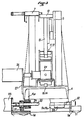
- FIG. 1 we see a schematic representation of a machine according to the invention in which a frame 1 has a lower structure 1a forming the base of the machine and an upper structure 1b constituting a bench longitudinal guide for a first upper carriage 2.
- the carriage 2 carries a rotary machining tool 3 around an arc transverse to the longitudinal direction of the bench.
- This tool is placed under the carriage and its rotational drive about its axis is provided by a motor (not shown) which can be easily fixed on the upper face of the carriage and the output shaft of which is simply connected by a strap 'drive extending in a vertical plane to cooperate with a driven pulley wedged on the tool shaft.
- the movement of the carriage 2 along the bench 1b can be ensured by any known means such as a rotary lead screw extending along the frame.
- a rack pinion drive device is preferred, the pinion being carried by the carriage and wedged on the output shaft of a motor also on board and fixed on the carriage.
- the rack is carried by the frame.
- the machine comprises a second lower carriage 4 capable of being moved along transverse guides 5a and 5b by means of a drive device shown in FIG. 3.
- This carriage 4 comprises a fixed superstructure of which a part 6 constitutes a support for jacks 7 for fixing the workpiece 8 (here a longitudinal upright) and another part, transversely distant from the first, constitutes a vertical wall 9 located opposite the cylinders 7 and constituting a support for the workpiece against which it is pressed by the cylinders.
- the carriage 4 carries a table 10 movable vertically, parallel to itself along the fixed wall 9.
- the device for moving the table which will be described in more detail with reference to the figure 2, comprises two slides 11 and 12 symmetrically movable from one another along longitudinal guides 13 and 14 carried by the carriage 4, and having an upper face 11a, 12a sloping cooperating with the branches 15a and 1ELb d 'A V-shaped piece 15 secured to the lower surface of the table 10. It can therefore be seen that by moving the slides closer or further apart, the table 10 is raised or lowered by the play of the sloping surfaces.
- this vertically movable table on the one hand, the depth of the tool can be adjusted and, on the other hand, it allows the part to be released from the tool by lowering its level.
- This arrangement is advantageous for, as will be seen later, turning the part over if another face is to be machined.
- the height of the wall 9 is greater than the maximum clearance of the table 10 so as to always constitute at least one barrier to the workpiece regardless of the position of the table, thus avoiding its lateral fall during movement towards the bottom of the table.
- the transverse displacement of the carriage 4 along the guides 5a and 5b allows the adjustment in position of the part relative to the tool which, in known manner, comprises several contiguous cutters making it possible to perform machining of different profiles on a part according to their relative position.
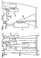
- FIG. 2 which is a diagrammatic half-section view of the table 10, carriage 4 connection, there is the slider 12 fitted on its face 12a with sliding pads 16, receiving a lining 17 integral with the branch 15b of the V-piece 15. At its lower part, the slide 12 also carries sliding shoes 18 cooperating with the guide 14 of the carriage 4.
- the slide 12 carries a nut 19 secured for example to one of its vertical walls 20 in which a screw 21 is engaged.
- the screw 21 is kept fixed in translation relative to the carriage 4 while being able to rotate in support bearings 22 and 23. It is coupled in rotation, by its end 21a situated in the central zone of the carriage 4 to one of the output shafts of a reduction gearbox 24 of which the input shaft is integral with the output of a motor visible in FIG. 3.
- the slider 11, not shown in this figure, is completely constructed completely symmetrical to that of the slide 12 and cooperates with a second screw 25 coupled to the other outlet of the bevel gear 24. If the screws rotate in opposite directions, their pitch will be reversed to obtain the symmetrical movements of separation and approximation of the slides.
- FIG 3 which is a schematic end view of the carriage 4 equipped with its superstructure and the table 10, there are some of the elements already described with the same references.
- the bevel gear 24 is associated with a motor 26 fixed by a console 27 on the carriage 4.
- the carriage 4 comprises sliding pads such as 28 cooperating with the transverse guides 5a, 5b that comprises the base 1a of the machine frame.
- the carriage 4 carries a vertical extension 4a, in its central region, provided with a nut 29 in which is engaged a screw 30 rotatably supported by bearings 31, 32 integral with the base 1a.
- This screw 30, stopped in translation, is coupled to the output shaft of a geared motor group 33 carried by the base 1a. The rotation of the screw 30 causes the carriage 4 to translate along the guides 5a, 5b.
- the motors 26 and 33, as well as the motor for driving the displacement of the upper carriage 2, along the bench 1b, can be associated with encoders and be controlled by a digital control device or an automaton according to a program of predetermined sequence of operations.
- Figures 4 and 5 finally, also schematically illustrate a device allowing the turning or rotation of the workpiece 8.
- the carriage 4 carries at one of its ends (that mentioned 4b in FIG. 1) a console 40 for fixing a lifting device 41 (for example a screw or pneumatic or hydraulic jack) fitted at its end free mite 41a of a clamp 42 with a horizontal axis and capable of pivoting about this axis by means of a motor device known in itself.
- this clamp At its end close to the table 10, this clamp has jaws 42a which can open 180 ° and close on one end of the workpiece 8 to be machined slightly projecting from the table 10, when this end is opposite the axis of the clamp.
- a retractable auxiliary support 43 is pivotally mounted on the superstructure of the carriage 4 on the side of the vertical wall 9 so as to be able to take two positions, one 43 ′ (FIG. 4) in which it is beyond the wall 9 relative to the table 10 and the other 43 "(FIG. 4 in dotted lines) in which its end is located substantially opposite the clamp 42 in its high position, that is to say at the level of the table 10 in its working position
- This auxiliary support 43 may be of the jack type with, at the end of the rod, a bracket 44 by which the part 8 is taken up and positioned.
- the machine operates as follows.
- the carriage 2 is initially at the left end ( Figure 1) of the bench 1b.
- the table 10 is in its high position at a level corresponding to the dimensions of the workpiece.
- the lower carriage 4 is in a position such that it is released from the tool laterally.
- the operator places the part on the table which is then clamped by the jacks 7 against the vertical wall 9.
- the actuators can be controlled by the operator or by the activation of an appropriate contactor detecting the presence of the room.
- the carriage 4 is then moved transversely to take the desired position relative to the tool 3.
- the clamp 42 is retracted to its lower level, that is to say below the level of the table, while the auxiliary support 43 is in its rest position behind the vertical plane of the wall 9.
- the working stroke of the carriage 2 is then controlled.
- the jacks 7 are loosened and the device 43 rocks to place itself in its position 43 "thus moving the end of the part 8 from the vertical wall 9.
- the table 10 descends while the part 42 rises to be placed opposite the end of the part 8 which is then supported by the device 43.
- the jaws 42a close on the part and the device 43 returning to its position 43 ′ the clamp 42 is rotated by 90 ° (by example) on the side of the wall 9, around its longitudinal axis.
- the jaws 42a then open and the released piece of wood falls on the table 10 below.
- the carriage 2 returns to its initial position while the table 10
- the jacks 7 lock the workpiece firmly against the wall 9.
- the carriage 4 is moved along its guides 5a and 5b to place the workpiece opposite the chosen tool part 3.
- the carriage 2 then performs the second machining
- the carriage 4 is then moved to the side to release the pi species and, the jacks 7 released, allow its evacuation and the loading of a new part.
- the operation of the described cycle can be carried out automatically by associating with different motor members sensors connected to a programmable control automaton or a numerically controlled device.
- the invention finds an interesting application in the field of the wood industry.
Landscapes
- Engineering & Computer Science (AREA)
- Mechanical Engineering (AREA)
- Life Sciences & Earth Sciences (AREA)
- Wood Science & Technology (AREA)
- Forests & Forestry (AREA)
- Milling, Drilling, And Turning Of Wood (AREA)
- Wing Frames And Configurations (AREA)
Claims (7)
dadurch gekennzeichnet, daß der Auflagetisch (10) vom Oberteil eines zweiten unteren Schlittens (4) getragen wird, der mit einer Antriebseinrichtung zu seiner Verschiebung in bezug auf den Rahmen (1) längs paralleler Führungen (5a, 5b) in einer zweiten horizontalen Querrichtung zusammenarbeitet, und daß die Einstelleinrichtung zwei gleitend auf den unteren Führungen (13, 14) des zweiten Schlittens (14) parallel zur genannten Längsrichtung angeordnete Gleitstücke (11, 12), von denen jedes eine mit einer der Seiten (15a, 15b) eines mit dem Auflagetisch (10) fest verbundenen V-förmigen Elementes (15) zusammenwirkende geneigte Oberseite (13a, 14a) besitzt, sowie zwei symmetrisch zu den Führungen (13,14) parallele Schrauben (21, 25)) umfaßt, die die gegenüberliegenden Abtriebswellen eines zentralen Winkelgetriebes (24) bilden, dessen Antriebswelle senkrecht zu diesen Führungen verläuft, wobei jede der Schrauben (21, 25) mit dem zugehörigen Gleitstück (11, 12) in der Weise eines Schraube-MutterSystems zusammenwirkt, um das eine oder andere dieser Gleitstücke entlang der Führungen aufeinander zu- oder voneinander weg zu bewegen.
Priority Applications (1)
| Application Number | Priority Date | Filing Date | Title |
|---|---|---|---|
| AT87401467T ATE46648T1 (de) | 1986-07-02 | 1987-06-25 | Holzbearbeitungsmaschine zur fertigung von fensterrahmen. |
Applications Claiming Priority (2)
| Application Number | Priority Date | Filing Date | Title |
|---|---|---|---|
| FR8609617A FR2600928A1 (fr) | 1986-07-02 | 1986-07-02 | Machine a bois notamment pour la realisation de cadres ou chassis de fenetre |
| FR8609617 | 1986-07-02 |
Publications (2)
| Publication Number | Publication Date |
|---|---|
| EP0252802A1 EP0252802A1 (de) | 1988-01-13 |
| EP0252802B1 true EP0252802B1 (de) | 1989-09-27 |
Family
ID=9336994
Family Applications (1)
| Application Number | Title | Priority Date | Filing Date |
|---|---|---|---|
| EP87401467A Expired EP0252802B1 (de) | 1986-07-02 | 1987-06-25 | Holzbearbeitungsmaschine zur Fertigung von Fensterrahmen |
Country Status (4)
| Country | Link |
|---|---|
| EP (1) | EP0252802B1 (de) |
| AT (1) | ATE46648T1 (de) |
| DE (1) | DE3760608D1 (de) |
| FR (1) | FR2600928A1 (de) |
Families Citing this family (5)
| Publication number | Priority date | Publication date | Assignee | Title |
|---|---|---|---|---|
| CN105415450B (zh) * | 2015-10-28 | 2017-12-15 | 孟玲琳 | 一种木工拼板切削机 |
| CN110587725B (zh) * | 2019-08-26 | 2024-05-28 | 吴善旺 | 雕铣机的翻转机构 |
| CN111993522B (zh) * | 2020-08-27 | 2022-06-24 | 南京涵铭置智能科技有限公司 | 一种家具生产用木框均匀切割设备 |
| CN114351980B (zh) * | 2021-12-27 | 2024-05-24 | 烟台红旗瑞景门窗有限公司 | 一种可调节的门窗组装架 |
| CN118596262B (zh) * | 2024-08-08 | 2024-11-22 | 江苏高昕建筑系统有限公司 | 一种新型建材制造用刨削装置 |
Family Cites Families (7)
| Publication number | Priority date | Publication date | Assignee | Title |
|---|---|---|---|---|
| FR9107E (fr) * | 1908-08-29 | Eugene Vauthier | Appareil pour le dressage des faces des navettes de tissage neuves ou usées | |
| CH100246A (de) * | 1922-04-13 | 1923-07-16 | Moser Hans | Langholzhobelmaschine. |
| US2639741A (en) * | 1950-09-29 | 1953-05-26 | William G Taylor | Self-propelled woodworking and finishing machine |
| DE890864C (de) * | 1951-09-12 | 1953-09-24 | Bruno Hoffmann | Werkbank, insbesondere zur Bearbeitung von Holz |
| US3380492A (en) * | 1966-04-21 | 1968-04-30 | Leo J. Konopka | Saw and miter guide |
| FR2051968A5 (de) * | 1969-07-03 | 1971-04-09 | Gaudy Leon | |
| DE2558226A1 (de) * | 1975-12-23 | 1977-07-14 | R & A Rationalisierung Und Aut | Tisch fuer werkzeugmaschinen zum aufspannen von werkzeugen oder werkstuecken |
-
1986
- 1986-07-02 FR FR8609617A patent/FR2600928A1/fr active Pending
-
1987
- 1987-06-25 DE DE8787401467T patent/DE3760608D1/de not_active Expired
- 1987-06-25 AT AT87401467T patent/ATE46648T1/de not_active IP Right Cessation
- 1987-06-25 EP EP87401467A patent/EP0252802B1/de not_active Expired
Also Published As
| Publication number | Publication date |
|---|---|
| ATE46648T1 (de) | 1989-10-15 |
| FR2600928A1 (fr) | 1988-01-08 |
| EP0252802A1 (de) | 1988-01-13 |
| DE3760608D1 (en) | 1989-11-02 |
Similar Documents
| Publication | Publication Date | Title |
|---|---|---|
| FR2535639A1 (de) | ||
| FR2584640A1 (fr) | Appareil d'echange de palettes pour machine d'usinage | |
| EP0036376B1 (de) | Automatisch verstellbare Vorschub- und Spannvorrichtung für die genaue Position einer Stange, z.B. anwendbar bei Abschneidmaschinen | |
| FR3054466A3 (fr) | Centre d’usinage pour profiles metalliques | |
| FR2585276A2 (fr) | Machine executant diverses operations d'usinage telles que tournage, fraisage, alesage | |
| FR2593728A1 (fr) | Poinconneuse a entrainement equilibre | |
| FR2492705A1 (fr) | Machine d'usinage a laser | |
| FR2540023A1 (fr) | Dispositif destine a deplacer, devant des moyens d'usinage et dans le sens de sa longueur, un profile a usiner | |
| FR2548069A1 (fr) | Dispositif pour manipuler ou positionner des pieces de construction | |
| FR2545625A1 (fr) | Procede et appareil de commande de machine de coupe | |
| EP0252802B1 (de) | Holzbearbeitungsmaschine zur Fertigung von Fensterrahmen | |
| FR2593729A1 (fr) | Machine de traitement de plaques, et notamment poinconneuse | |
| FR2573334A1 (fr) | Presse de soudage a mecanisme de soulevement de piece | |
| FR2541926A1 (fr) | Machine-outil a travailler le bois | |
| JP2001179520A (ja) | パイプ開先加工機 | |
| EP0015215A1 (de) | Lader oder Auszieher von Stücken | |
| EP0048677B1 (de) | Universeller Arbeitstisch mit auswechselbaren Arbeitsplatten | |
| FR2510452A1 (fr) | Procede et machine pour le faconnage des aretes de vitrages | |
| EP0007263A1 (de) | Verbesserungen an Abtrennmaschinen für Gerad- und Schrägschnitte, welche in Bohrmaschinen eingebaut werden können | |
| FR2467033A3 (fr) | Appareil d'introduction de metal fondu, particulierement pour machine a couler en coquille | |
| EP0111428A1 (de) | Vorrichtung zum Positionieren und Verschweissen des Bodens und der Schlingerwände mit der Wand eines Behälters oder Tanks | |
| FR2483288A1 (fr) | Presse a chassis, notamment pour chassis de fenetres | |
| FR2703617A1 (fr) | Dispositif de soutien à autocentrage asservi pour cadreuse. | |
| FR2703286A1 (fr) | Procédé d'usinage des chants de dalles de pierre et appareil le mettant en Óoeuvre. | |
| FR2615770A1 (fr) | Machine a fraiser et a percer notamment pour des profiles creux a parois minces |
Legal Events
| Date | Code | Title | Description |
|---|---|---|---|
| PUAI | Public reference made under article 153(3) epc to a published international application that has entered the european phase |
Free format text: ORIGINAL CODE: 0009012 |
|
| 17P | Request for examination filed |
Effective date: 19870629 |
|
| AK | Designated contracting states |
Kind code of ref document: A1 Designated state(s): AT BE CH DE ES GB IT LI LU NL SE |
|
| 17Q | First examination report despatched |
Effective date: 19890228 |
|
| GRAA | (expected) grant |
Free format text: ORIGINAL CODE: 0009210 |
|
| AK | Designated contracting states |
Kind code of ref document: B1 Designated state(s): AT BE CH DE ES GB IT LI LU NL SE |
|
| PG25 | Lapsed in a contracting state [announced via postgrant information from national office to epo] |
Ref country code: SE Effective date: 19890927 Ref country code: NL Effective date: 19890927 Ref country code: GB Effective date: 19890927 Ref country code: AT Effective date: 19890927 |
|
| REF | Corresponds to: |
Ref document number: 46648 Country of ref document: AT Date of ref document: 19891015 Kind code of ref document: T |
|
| REF | Corresponds to: |
Ref document number: 3760608 Country of ref document: DE Date of ref document: 19891102 |
|
| ITF | It: translation for a ep patent filed | ||
| PG25 | Lapsed in a contracting state [announced via postgrant information from national office to epo] |
Ref country code: ES Free format text: LAPSE BECAUSE OF FAILURE TO SUBMIT A TRANSLATION OF THE DESCRIPTION OR TO PAY THE FEE WITHIN THE PRESCRIBED TIME-LIMIT Effective date: 19900107 |
|
| NLV1 | Nl: lapsed or annulled due to failure to fulfill the requirements of art. 29p and 29m of the patents act | ||
| GBV | Gb: ep patent (uk) treated as always having been void in accordance with gb section 77(7)/1977 [no translation filed] | ||
| PLBE | No opposition filed within time limit |
Free format text: ORIGINAL CODE: 0009261 |
|
| STAA | Information on the status of an ep patent application or granted ep patent |
Free format text: STATUS: NO OPPOSITION FILED WITHIN TIME LIMIT |
|
| 26N | No opposition filed | ||
| PGFP | Annual fee paid to national office [announced via postgrant information from national office to epo] |
Ref country code: LU Payment date: 19910619 Year of fee payment: 5 |
|
| PGFP | Annual fee paid to national office [announced via postgrant information from national office to epo] |
Ref country code: BE Payment date: 19910627 Year of fee payment: 5 |
|
| ITTA | It: last paid annual fee | ||
| PGFP | Annual fee paid to national office [announced via postgrant information from national office to epo] |
Ref country code: CH Payment date: 19910709 Year of fee payment: 5 |
|
| PGFP | Annual fee paid to national office [announced via postgrant information from national office to epo] |
Ref country code: DE Payment date: 19910725 Year of fee payment: 5 |
|
| EPTA | Lu: last paid annual fee | ||
| PG25 | Lapsed in a contracting state [announced via postgrant information from national office to epo] |
Ref country code: LU Free format text: LAPSE BECAUSE OF NON-PAYMENT OF DUE FEES Effective date: 19920625 |
|
| PG25 | Lapsed in a contracting state [announced via postgrant information from national office to epo] |
Ref country code: LI Effective date: 19920630 Ref country code: CH Effective date: 19920630 Ref country code: BE Effective date: 19920630 |
|
| BERE | Be: lapsed |
Owner name: BADONNEL RENE Effective date: 19920630 |
|
| REG | Reference to a national code |
Ref country code: CH Ref legal event code: PL |
|
| PG25 | Lapsed in a contracting state [announced via postgrant information from national office to epo] |
Ref country code: DE Effective date: 19930302 |
|
| PG25 | Lapsed in a contracting state [announced via postgrant information from national office to epo] |
Ref country code: IT Free format text: LAPSE BECAUSE OF NON-PAYMENT OF DUE FEES;WARNING: LAPSES OF ITALIAN PATENTS WITH EFFECTIVE DATE BEFORE 2007 MAY HAVE OCCURRED AT ANY TIME BEFORE 2007. THE CORRECT EFFECTIVE DATE MAY BE DIFFERENT FROM THE ONE RECORDED. Effective date: 20050625 |