EP0252664B1 - Verfahren und Einrichtung zum Formen einer Palette mit tiefgezogenen Füssen - Google Patents
Verfahren und Einrichtung zum Formen einer Palette mit tiefgezogenen Füssen Download PDFInfo
- Publication number
- EP0252664B1 EP0252664B1 EP87305772A EP87305772A EP0252664B1 EP 0252664 B1 EP0252664 B1 EP 0252664B1 EP 87305772 A EP87305772 A EP 87305772A EP 87305772 A EP87305772 A EP 87305772A EP 0252664 B1 EP0252664 B1 EP 0252664B1
- Authority
- EP
- European Patent Office
- Prior art keywords
- layer
- mat
- wood
- caul sheet
- wood flakes
- Prior art date
- Legal status (The legal status is an assumption and is not a legal conclusion. Google has not performed a legal analysis and makes no representation as to the accuracy of the status listed.)
- Expired - Lifetime
Links
- 238000000034 method Methods 0.000 title claims description 23
- 239000002023 wood Substances 0.000 claims abstract description 116
- 239000002245 particle Substances 0.000 claims abstract description 26
- 239000011230 binding agent Substances 0.000 claims abstract description 16
- 238000000151 deposition Methods 0.000 claims abstract description 16
- 238000003825 pressing Methods 0.000 claims abstract description 8
- 239000000203 mixture Substances 0.000 claims abstract description 7
- 210000000569 greater omentum Anatomy 0.000 claims description 113
- 238000000465 moulding Methods 0.000 claims description 8
- 239000000463 material Substances 0.000 description 14
- 238000010276 construction Methods 0.000 description 7
- 230000015572 biosynthetic process Effects 0.000 description 5
- 238000004519 manufacturing process Methods 0.000 description 4
- 239000001993 wax Substances 0.000 description 4
- 230000006835 compression Effects 0.000 description 3
- 238000007906 compression Methods 0.000 description 3
- 238000002156 mixing Methods 0.000 description 3
- 241000183024 Populus tremula Species 0.000 description 2
- 239000002131 composite material Substances 0.000 description 2
- 238000009826 distribution Methods 0.000 description 2
- 235000007173 Abies balsamea Nutrition 0.000 description 1
- 241000208140 Acer Species 0.000 description 1
- 239000004857 Balsam Substances 0.000 description 1
- 235000018185 Betula X alpestris Nutrition 0.000 description 1
- 235000018212 Betula X uliginosa Nutrition 0.000 description 1
- 241000218645 Cedrus Species 0.000 description 1
- 240000000731 Fagus sylvatica Species 0.000 description 1
- 235000010099 Fagus sylvatica Nutrition 0.000 description 1
- 239000001828 Gelatine Substances 0.000 description 1
- 244000018716 Impatiens biflora Species 0.000 description 1
- 241000218657 Picea Species 0.000 description 1
- 235000008331 Pinus X rigitaeda Nutrition 0.000 description 1
- 241000018646 Pinus brutia Species 0.000 description 1
- 235000011613 Pinus brutia Nutrition 0.000 description 1
- 241000202951 Populus grandidentata Species 0.000 description 1
- 240000004923 Populus tremuloides Species 0.000 description 1
- 235000011263 Populus tremuloides Nutrition 0.000 description 1
- 229920001131 Pulp (paper) Polymers 0.000 description 1
- 241000219492 Quercus Species 0.000 description 1
- 241001106462 Ulmus Species 0.000 description 1
- 239000000654 additive Substances 0.000 description 1
- 239000000853 adhesive Substances 0.000 description 1
- 230000001070 adhesive effect Effects 0.000 description 1
- 230000000295 complement effect Effects 0.000 description 1
- 238000007796 conventional method Methods 0.000 description 1
- 238000001035 drying Methods 0.000 description 1
- 238000001125 extrusion Methods 0.000 description 1
- 239000011121 hardwood Substances 0.000 description 1
- 239000007788 liquid Substances 0.000 description 1
- 239000002184 metal Substances 0.000 description 1
- 230000002093 peripheral effect Effects 0.000 description 1
- 229920001228 polyisocyanate Polymers 0.000 description 1
- 239000005056 polyisocyanate Substances 0.000 description 1
- 239000011369 resultant mixture Substances 0.000 description 1
- 239000011122 softwood Substances 0.000 description 1
- 241000894007 species Species 0.000 description 1
- 238000003860 storage Methods 0.000 description 1
- 238000009966 trimming Methods 0.000 description 1
Images


Classifications
-
- B—PERFORMING OPERATIONS; TRANSPORTING
- B27—WORKING OR PRESERVING WOOD OR SIMILAR MATERIAL; NAILING OR STAPLING MACHINES IN GENERAL
- B27N—MANUFACTURE BY DRY PROCESSES OF ARTICLES, WITH OR WITHOUT ORGANIC BINDING AGENTS, MADE FROM PARTICLES OR FIBRES CONSISTING OF WOOD OR OTHER LIGNOCELLULOSIC OR LIKE ORGANIC MATERIAL
- B27N5/00—Manufacture of non-flat articles
-
- B—PERFORMING OPERATIONS; TRANSPORTING
- B65—CONVEYING; PACKING; STORING; HANDLING THIN OR FILAMENTARY MATERIAL
- B65D—CONTAINERS FOR STORAGE OR TRANSPORT OF ARTICLES OR MATERIALS, e.g. BAGS, BARRELS, BOTTLES, BOXES, CANS, CARTONS, CRATES, DRUMS, JARS, TANKS, HOPPERS, FORWARDING CONTAINERS; ACCESSORIES, CLOSURES, OR FITTINGS THEREFOR; PACKAGING ELEMENTS; PACKAGES
- B65D19/00—Pallets or like platforms, with or without side walls, for supporting loads to be lifted or lowered
- B65D19/0004—Rigid pallets without side walls
- B65D19/0006—Rigid pallets without side walls the load supporting surface being made of a single element
- B65D19/003—Rigid pallets without side walls the load supporting surface being made of a single element forming discontinuous or non-planar contact surfaces
- B65D19/0032—Rigid pallets without side walls the load supporting surface being made of a single element forming discontinuous or non-planar contact surfaces the base surface being made of a single element
- B65D19/0036—Rigid pallets without side walls the load supporting surface being made of a single element forming discontinuous or non-planar contact surfaces the base surface being made of a single element forming discontinuous or non-planar contact surfaces
- B65D19/004—Rigid pallets without side walls the load supporting surface being made of a single element forming discontinuous or non-planar contact surfaces the base surface being made of a single element forming discontinuous or non-planar contact surfaces and each contact surface having a discrete foot-like shape
-
- B—PERFORMING OPERATIONS; TRANSPORTING
- B65—CONVEYING; PACKING; STORING; HANDLING THIN OR FILAMENTARY MATERIAL
- B65D—CONTAINERS FOR STORAGE OR TRANSPORT OF ARTICLES OR MATERIALS, e.g. BAGS, BARRELS, BOTTLES, BOXES, CANS, CARTONS, CRATES, DRUMS, JARS, TANKS, HOPPERS, FORWARDING CONTAINERS; ACCESSORIES, CLOSURES, OR FITTINGS THEREFOR; PACKAGING ELEMENTS; PACKAGES
- B65D2519/00—Pallets or like platforms, with or without side walls, for supporting loads to be lifted or lowered
- B65D2519/00004—Details relating to pallets
- B65D2519/00009—Materials
- B65D2519/00014—Materials for the load supporting surface
- B65D2519/00029—Wood
-
- B—PERFORMING OPERATIONS; TRANSPORTING
- B65—CONVEYING; PACKING; STORING; HANDLING THIN OR FILAMENTARY MATERIAL
- B65D—CONTAINERS FOR STORAGE OR TRANSPORT OF ARTICLES OR MATERIALS, e.g. BAGS, BARRELS, BOTTLES, BOXES, CANS, CARTONS, CRATES, DRUMS, JARS, TANKS, HOPPERS, FORWARDING CONTAINERS; ACCESSORIES, CLOSURES, OR FITTINGS THEREFOR; PACKAGING ELEMENTS; PACKAGES
- B65D2519/00—Pallets or like platforms, with or without side walls, for supporting loads to be lifted or lowered
- B65D2519/00004—Details relating to pallets
- B65D2519/00009—Materials
- B65D2519/00014—Materials for the load supporting surface
- B65D2519/00039—Agglomerates, i.e. different materials mixed together
-
- B—PERFORMING OPERATIONS; TRANSPORTING
- B65—CONVEYING; PACKING; STORING; HANDLING THIN OR FILAMENTARY MATERIAL
- B65D—CONTAINERS FOR STORAGE OR TRANSPORT OF ARTICLES OR MATERIALS, e.g. BAGS, BARRELS, BOTTLES, BOXES, CANS, CARTONS, CRATES, DRUMS, JARS, TANKS, HOPPERS, FORWARDING CONTAINERS; ACCESSORIES, CLOSURES, OR FITTINGS THEREFOR; PACKAGING ELEMENTS; PACKAGES
- B65D2519/00—Pallets or like platforms, with or without side walls, for supporting loads to be lifted or lowered
- B65D2519/00004—Details relating to pallets
- B65D2519/00009—Materials
- B65D2519/00049—Materials for the base surface
- B65D2519/00064—Wood
-
- B—PERFORMING OPERATIONS; TRANSPORTING
- B65—CONVEYING; PACKING; STORING; HANDLING THIN OR FILAMENTARY MATERIAL
- B65D—CONTAINERS FOR STORAGE OR TRANSPORT OF ARTICLES OR MATERIALS, e.g. BAGS, BARRELS, BOTTLES, BOXES, CANS, CARTONS, CRATES, DRUMS, JARS, TANKS, HOPPERS, FORWARDING CONTAINERS; ACCESSORIES, CLOSURES, OR FITTINGS THEREFOR; PACKAGING ELEMENTS; PACKAGES
- B65D2519/00—Pallets or like platforms, with or without side walls, for supporting loads to be lifted or lowered
- B65D2519/00004—Details relating to pallets
- B65D2519/00009—Materials
- B65D2519/00049—Materials for the base surface
- B65D2519/00074—Agglomerates, i.e. different materials mixed together
-
- B—PERFORMING OPERATIONS; TRANSPORTING
- B65—CONVEYING; PACKING; STORING; HANDLING THIN OR FILAMENTARY MATERIAL
- B65D—CONTAINERS FOR STORAGE OR TRANSPORT OF ARTICLES OR MATERIALS, e.g. BAGS, BARRELS, BOTTLES, BOXES, CANS, CARTONS, CRATES, DRUMS, JARS, TANKS, HOPPERS, FORWARDING CONTAINERS; ACCESSORIES, CLOSURES, OR FITTINGS THEREFOR; PACKAGING ELEMENTS; PACKAGES
- B65D2519/00—Pallets or like platforms, with or without side walls, for supporting loads to be lifted or lowered
- B65D2519/00004—Details relating to pallets
- B65D2519/00258—Overall construction
- B65D2519/00263—Overall construction of the pallet
- B65D2519/00268—Overall construction of the pallet made of one piece
-
- B—PERFORMING OPERATIONS; TRANSPORTING
- B65—CONVEYING; PACKING; STORING; HANDLING THIN OR FILAMENTARY MATERIAL
- B65D—CONTAINERS FOR STORAGE OR TRANSPORT OF ARTICLES OR MATERIALS, e.g. BAGS, BARRELS, BOTTLES, BOXES, CANS, CARTONS, CRATES, DRUMS, JARS, TANKS, HOPPERS, FORWARDING CONTAINERS; ACCESSORIES, CLOSURES, OR FITTINGS THEREFOR; PACKAGING ELEMENTS; PACKAGES
- B65D2519/00—Pallets or like platforms, with or without side walls, for supporting loads to be lifted or lowered
- B65D2519/00004—Details relating to pallets
- B65D2519/00258—Overall construction
- B65D2519/00283—Overall construction of the load supporting surface
- B65D2519/00288—Overall construction of the load supporting surface made of one piece
-
- B—PERFORMING OPERATIONS; TRANSPORTING
- B65—CONVEYING; PACKING; STORING; HANDLING THIN OR FILAMENTARY MATERIAL
- B65D—CONTAINERS FOR STORAGE OR TRANSPORT OF ARTICLES OR MATERIALS, e.g. BAGS, BARRELS, BOTTLES, BOXES, CANS, CARTONS, CRATES, DRUMS, JARS, TANKS, HOPPERS, FORWARDING CONTAINERS; ACCESSORIES, CLOSURES, OR FITTINGS THEREFOR; PACKAGING ELEMENTS; PACKAGES
- B65D2519/00—Pallets or like platforms, with or without side walls, for supporting loads to be lifted or lowered
- B65D2519/00004—Details relating to pallets
- B65D2519/00258—Overall construction
- B65D2519/00313—Overall construction of the base surface
- B65D2519/00318—Overall construction of the base surface made of one piece
-
- B—PERFORMING OPERATIONS; TRANSPORTING
- B65—CONVEYING; PACKING; STORING; HANDLING THIN OR FILAMENTARY MATERIAL
- B65D—CONTAINERS FOR STORAGE OR TRANSPORT OF ARTICLES OR MATERIALS, e.g. BAGS, BARRELS, BOTTLES, BOXES, CANS, CARTONS, CRATES, DRUMS, JARS, TANKS, HOPPERS, FORWARDING CONTAINERS; ACCESSORIES, CLOSURES, OR FITTINGS THEREFOR; PACKAGING ELEMENTS; PACKAGES
- B65D2519/00—Pallets or like platforms, with or without side walls, for supporting loads to be lifted or lowered
- B65D2519/00004—Details relating to pallets
- B65D2519/00258—Overall construction
- B65D2519/00313—Overall construction of the base surface
- B65D2519/00328—Overall construction of the base surface shape of the contact surface of the base
- B65D2519/00338—Overall construction of the base surface shape of the contact surface of the base contact surface having a discrete foot-like shape
-
- Y—GENERAL TAGGING OF NEW TECHNOLOGICAL DEVELOPMENTS; GENERAL TAGGING OF CROSS-SECTIONAL TECHNOLOGIES SPANNING OVER SEVERAL SECTIONS OF THE IPC; TECHNICAL SUBJECTS COVERED BY FORMER USPC CROSS-REFERENCE ART COLLECTIONS [XRACs] AND DIGESTS
- Y10—TECHNICAL SUBJECTS COVERED BY FORMER USPC
- Y10S—TECHNICAL SUBJECTS COVERED BY FORMER USPC CROSS-REFERENCE ART COLLECTIONS [XRACs] AND DIGESTS
- Y10S108/00—Horizontally supported planar surfaces
- Y10S108/901—Synthetic plastic industrial platform, e.g. pallet
-
- Y—GENERAL TAGGING OF NEW TECHNOLOGICAL DEVELOPMENTS; GENERAL TAGGING OF CROSS-SECTIONAL TECHNOLOGIES SPANNING OVER SEVERAL SECTIONS OF THE IPC; TECHNICAL SUBJECTS COVERED BY FORMER USPC CROSS-REFERENCE ART COLLECTIONS [XRACs] AND DIGESTS
- Y10—TECHNICAL SUBJECTS COVERED BY FORMER USPC
- Y10S—TECHNICAL SUBJECTS COVERED BY FORMER USPC CROSS-REFERENCE ART COLLECTIONS [XRACs] AND DIGESTS
- Y10S264/00—Plastic and nonmetallic article shaping or treating: processes
- Y10S264/57—Processes of forming layered products
-
- Y—GENERAL TAGGING OF NEW TECHNOLOGICAL DEVELOPMENTS; GENERAL TAGGING OF CROSS-SECTIONAL TECHNOLOGIES SPANNING OVER SEVERAL SECTIONS OF THE IPC; TECHNICAL SUBJECTS COVERED BY FORMER USPC CROSS-REFERENCE ART COLLECTIONS [XRACs] AND DIGESTS
- Y10—TECHNICAL SUBJECTS COVERED BY FORMER USPC
- Y10T—TECHNICAL SUBJECTS COVERED BY FORMER US CLASSIFICATION
- Y10T428/00—Stock material or miscellaneous articles
- Y10T428/25—Web or sheet containing structurally defined element or component and including a second component containing structurally defined particles
- Y10T428/253—Cellulosic [e.g., wood, paper, cork, rayon, etc.]
Definitions
- means are also provided for supporting the caul plate 32 beneath the discharge end 39 of the conveyor belt 38 such that the caul plate 32 can be reciprocated back and forth beneath the discharge end 39 of the conveyor and such that uniform thin layers of wood flakes will be deposited on the caul plate 32 as it is moved back and forth. As the flakes drop onto the caul plate, they will become oriented such that they will lie in horizontal planes and in interweaved loosely felted relation.
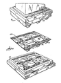
- the caul plate 32 will have a configuration as illustrated in Fig. 4 and defining the bottom of the pallet 10 to be formed, and the lower die 68 of the press 70 is constructed such that it can house the caul plate 32, with the caul plate 32 positioned directly in the lower die 68 during the pressing operation.
- the caul plate 32 having the flake aligner 80 positioned thereon will be moved beneath the mat former four times to form a first layer of wood flakes.
- the flake aligner 80 is then removed and a second flake aligner 90 (Fig. 10) is positioned above the caul plate 32.
- the second flake aligner 90 is intended to provide a means for causing a portion of the loosely felted flakes forming the next layer to be aligned in directions transverse to the direction of alignment of the wood flakes of the first layer.
- the second flake aligner 90 includes a rectangular frame 92 similar to frame 82 and adapted to be positioned above the caul sheet 32 and to be supported by the carriage 56.
- the caul plate 32 having the second flake aligner 90 thereon is moved back and forth beneath discharge end 39 of the conveyor belt 38 for eight passes to build up additional layers of wood flakes on the caul sheet 32.
- the second flake aligner 90 is then removed and a third frame structure 100 is placed above the caul sheet 32 for the remainder of the passes under the mat former and until a mat having a thickness of approximately 15,24cm (6 inches) is formed on the caul sheet.
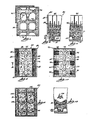
- the third frame structure 100 includes a rectangular frame 102 like those of the first and second flake aligners, and further includes a plurality of intersecting rods 104 supported by the rectangular frame 102, the intersecting rods 104 supporting a plurality of cylinders 106 provided to cause the flakes falling onto the mat to be diverted away from areas of the mat. Diversion of flakes from these areas during formation of the top layers of the mat aids in molding of channels during the pressing operation.
- a pallet having relatively long legs can be formed in a single stage compressing operation and without formation of tears or voids in the mat material during the pressing operation.
Landscapes
- Engineering & Computer Science (AREA)
- Life Sciences & Earth Sciences (AREA)
- Mechanical Engineering (AREA)
- Manufacturing & Machinery (AREA)
- Wood Science & Technology (AREA)
- Forests & Forestry (AREA)
- Dry Formation Of Fiberboard And The Like (AREA)
- Pallets (AREA)
- Blow-Moulding Or Thermoforming Of Plastics Or The Like (AREA)
Claims (18)
Priority Applications (1)
| Application Number | Priority Date | Filing Date | Title |
|---|---|---|---|
| AT87305772T ATE56650T1 (de) | 1986-06-30 | 1987-06-30 | Verfahren und einrichtung zum formen einer palette mit tiefgezogenen fuessen. |
Applications Claiming Priority (2)
| Application Number | Priority Date | Filing Date | Title |
|---|---|---|---|
| US06/879,937 US4790966A (en) | 1986-06-30 | 1986-06-30 | Method for forming a pallet with deep drawn legs |
| US879937 | 1986-06-30 |
Publications (3)
| Publication Number | Publication Date |
|---|---|
| EP0252664A2 EP0252664A2 (de) | 1988-01-13 |
| EP0252664A3 EP0252664A3 (en) | 1988-07-13 |
| EP0252664B1 true EP0252664B1 (de) | 1990-09-19 |
Family
ID=25375192
Family Applications (1)
| Application Number | Title | Priority Date | Filing Date |
|---|---|---|---|
| EP87305772A Expired - Lifetime EP0252664B1 (de) | 1986-06-30 | 1987-06-30 | Verfahren und Einrichtung zum Formen einer Palette mit tiefgezogenen Füssen |
Country Status (5)
| Country | Link |
|---|---|
| US (1) | US4790966A (de) |
| EP (1) | EP0252664B1 (de) |
| AT (1) | ATE56650T1 (de) |
| CA (1) | CA1282716C (de) |
| DE (1) | DE3765033D1 (de) |
Families Citing this family (60)
| Publication number | Priority date | Publication date | Assignee | Title |
|---|---|---|---|---|
| JPH0784002B2 (ja) * | 1985-12-09 | 1995-09-13 | トヨタ自動車株式会社 | 木質系成形体 |
| GB8729894D0 (en) * | 1987-12-22 | 1988-02-03 | Compak Syst | Apparatus for laying matt of fibrous material |
| USD311803S (en) | 1988-01-15 | 1990-10-30 | R.H. Murphy Co. | Pallet |
| JP2654519B2 (ja) * | 1989-04-28 | 1997-09-17 | 曙ブレーキ工業株式会社 | 摩擦材の予備成形装置 |
| US4960553A (en) * | 1990-02-12 | 1990-10-02 | Board Of Control Michigan Technological University | Method for forming articles having deep drawn portions from matted wood flakes |
| US5824246A (en) | 1991-03-29 | 1998-10-20 | Engineered Composites | Method of forming a thermoactive binder composite |
| CA2100320C (en) * | 1992-08-31 | 2011-02-08 | Michael J. Deaner | Advanced polymer wood composite |
| CA2100319C (en) * | 1992-08-31 | 2003-10-07 | Michael J. Deaner | Advanced polymer/wood composite structural member |
| US6004668A (en) * | 1992-08-31 | 1999-12-21 | Andersen Corporation | Advanced polymer wood composite |
| US5406768A (en) * | 1992-09-01 | 1995-04-18 | Andersen Corporation | Advanced polymer and wood fiber composite structural component |
| US5441801A (en) * | 1993-02-12 | 1995-08-15 | Andersen Corporation | Advanced polymer/wood composite pellet process |
| US5435954A (en) * | 1993-10-08 | 1995-07-25 | Riverwood International Corporation | Method for forming articles of reinforced composite material |
| ES2109102T3 (es) * | 1994-05-04 | 1998-01-01 | Viessmann Hans | Palet para el transporte de cargas. |
| USD369743S (en) | 1995-02-28 | 1996-05-14 | Trienda Corporation | Plastic pallet |
| US5585054A (en) * | 1995-03-08 | 1996-12-17 | Evans; Daniel W. | Method of making a composite fiber reinforced polyethylene |
| US5776281A (en) * | 1995-03-08 | 1998-07-07 | Evans; Daniel W. | Method of manufacturing a pallet made of composite fiber reinforced polyolefin |
| US5948524A (en) * | 1996-01-08 | 1999-09-07 | Andersen Corporation | Advanced engineering resin and wood fiber composite |
| US5847016A (en) * | 1996-05-16 | 1998-12-08 | Marley Mouldings Inc. | Polymer and wood flour composite extrusion |
| US5855832A (en) * | 1996-06-27 | 1999-01-05 | Clausi; Robert N. | Method of molding powdered plant fiber into high density materials |
| US6117924A (en) | 1996-10-22 | 2000-09-12 | Crane Plastics Company Limited Partnership | Extrusion of synthetic wood material |
| US6180257B1 (en) | 1996-10-29 | 2001-01-30 | Crane Plastics Company Limited Partnership | Compression molding of synthetic wood material |
| US6464913B1 (en) | 1997-09-05 | 2002-10-15 | Crane Plastics Company Limited Partnership | In-line compounding and extrusion system |
| US6344268B1 (en) | 1998-04-03 | 2002-02-05 | Certainteed Corporation | Foamed polymer-fiber composite |
| GB2339760A (en) * | 1998-07-17 | 2000-02-09 | Thomas Gilligan | Moulded Pallet |
| US6773791B1 (en) * | 1999-03-31 | 2004-08-10 | Masonite Corporation | Composite building components, and method of making same |
| ES2276678T3 (es) | 1999-03-31 | 2007-07-01 | Masonite Corporation | Componentes compuestos para la construccion y procedimiento de fabricacion de los mismos. |
| US6280667B1 (en) | 1999-04-19 | 2001-08-28 | Andersen Corporation | Process for making thermoplastic-biofiber composite materials and articles including a poly(vinylchloride) component |
| US6971211B1 (en) | 1999-05-22 | 2005-12-06 | Crane Plastics Company Llc | Cellulosic/polymer composite material |
| US6662515B2 (en) | 2000-03-31 | 2003-12-16 | Crane Plastics Company Llc | Synthetic wood post cap |
| US6756105B1 (en) | 2000-05-02 | 2004-06-29 | Bruce A. Haataja | Article and method using larger draft angle to pinch trim edge of molded wood strand products |
| US6635208B2 (en) | 2000-05-02 | 2003-10-21 | Strandwood Molding, Inc. | Method for forming narrow channels in a wood flake article |
| US6592792B2 (en) | 2000-05-02 | 2003-07-15 | Strandwood Molding, Inc. | Method of making a strandboard molding having holes at angles of 20 degrees to vertical or more |
| US6761844B1 (en) | 2000-05-30 | 2004-07-13 | Bruce A. Haataja | Spring-loaded ejectors for wood strand molding |
| US6843946B1 (en) | 2000-07-31 | 2005-01-18 | Gfp Strandwood Corp. | Stepped punch for forming holes in molded wood strand parts |
| US6579605B2 (en) | 2000-07-31 | 2003-06-17 | Crane Plastics Company Llc | Multilayer synthetic wood component |
| US7112295B1 (en) | 2000-11-03 | 2006-09-26 | Gfp Strandwood Corp. | Method for simultaneously molding and shearing multiple wood strand molded parts |
| US6916523B2 (en) | 2000-11-29 | 2005-07-12 | Gfp Strandwood Corp. | Wood strand molded parts having three-dimensionally curved or bent channels, and method for making same |
| US6637213B2 (en) | 2001-01-19 | 2003-10-28 | Crane Plastics Company Llc | Cooling of extruded and compression molded materials |
| US7017352B2 (en) | 2001-01-19 | 2006-03-28 | Crane Plastics Company Llc | Cooling of extruded and compression molded materials |
| US6578368B1 (en) | 2001-01-19 | 2003-06-17 | Crane Plastics Company Llc | Cryogenic cooling of extruded and compression molded materials |
| US6830797B2 (en) * | 2001-02-21 | 2004-12-14 | Gfp Strandwood Corporation | Wood strand molded part having holes with densified and thinner perimeters and method of making same |
| US6846553B2 (en) * | 2001-03-14 | 2005-01-25 | Gfp Strandwood Corp. | Wood strand molded parts salted with fines to improve molding detail, and method of making same |
| US6588163B2 (en) * | 2001-07-17 | 2003-07-08 | Martin Wang | Relief engraved doorplate |
| US6632863B2 (en) | 2001-10-25 | 2003-10-14 | Crane Plastics Company Llc | Cellulose/polyolefin composite pellet |
| US6780359B1 (en) | 2002-01-29 | 2004-08-24 | Crane Plastics Company Llc | Synthetic wood composite material and method for molding |
| US6887064B2 (en) * | 2002-06-18 | 2005-05-03 | Sung Kuk Soh | Method and apparatus for producing non-planar formed parts using compaction molding compounds, and parts formed using same |
| US20040032054A1 (en) * | 2002-08-13 | 2004-02-19 | Moeller David W. | Compression molded panels |
| US7186457B1 (en) | 2002-11-27 | 2007-03-06 | Crane Plastics Company Llc | Cellulosic composite component |
| US20050061211A1 (en) * | 2003-09-19 | 2005-03-24 | Worthington Industries | Metal pallet |
| US20050193926A1 (en) * | 2004-03-03 | 2005-09-08 | Sonoco Development, Inc. | Pallet formed from molded fibrous panel material |
| US20050227040A1 (en) * | 2004-04-13 | 2005-10-13 | Toupalik John M | Board formed from a wood fiber composite |
| US8074339B1 (en) | 2004-11-22 | 2011-12-13 | The Crane Group Companies Limited | Methods of manufacturing a lattice having a distressed appearance |
| US8167275B1 (en) | 2005-11-30 | 2012-05-01 | The Crane Group Companies Limited | Rail system and method for assembly |
| US7743567B1 (en) | 2006-01-20 | 2010-06-29 | The Crane Group Companies Limited | Fiberglass/cellulosic composite and method for molding |
| US20100015390A1 (en) * | 2006-07-17 | 2010-01-21 | Huber Engineered Woods Llc | Wood composite material containing balsam fir |
| US7560169B2 (en) * | 2006-07-17 | 2009-07-14 | Huber Engineered Woods Llc | Wood composite material containing balsam fir |
| US8141723B2 (en) * | 2006-08-18 | 2012-03-27 | Plano Molding Company | Inverted cell honeycomb structure shelving |
| US8460797B1 (en) | 2006-12-29 | 2013-06-11 | Timbertech Limited | Capped component and method for forming |
| WO2024039387A1 (en) * | 2022-08-19 | 2024-02-22 | Paul Zhang | Multi-layer composite pulp product, and system and process for manufacturing same |
| CN116513620A (zh) * | 2023-04-04 | 2023-08-01 | 台州市黄岩鑫普塑模有限公司 | 一种塑料托盘及其挤出压铸模具 |
Family Cites Families (21)
| Publication number | Priority date | Publication date | Assignee | Title |
|---|---|---|---|---|
| US2372055A (en) * | 1944-02-14 | 1945-03-20 | Robert H Braun | Pallet |
| DE976840C (de) * | 1954-03-12 | 1964-06-04 | Max Himmelheber Dipl Ing | Verfahren und Vorrichtung zum Aufschuetten von mit Bindemitteln versetzten, in ihrerLage nach einer bestimmten Richtung auszurichtenden laenglichen Holzspaenen od. dgl.zur anschliessenden Herstellung von Holzspanplatten oder -formteilen |
| US3115431A (en) * | 1959-09-10 | 1963-12-24 | Abitibi Power & Paper Co | Method and apparatus for making oriented wood particle board |
| US4073851A (en) * | 1970-07-15 | 1978-02-14 | Werzalit Pressholzwerk J.F. Werz K.G. | Method of making molded bodies from ligno-cellulose particles |
| US4078030A (en) * | 1973-03-13 | 1978-03-07 | Werzalik-Pressholzwerk J.F. Werz Jr. Kg | Molding of articles from fibrous material |
| US4061813A (en) * | 1974-06-11 | 1977-12-06 | The United States Of America As Represented By The Secretary Of Agriculture | Combination sheathing support - member building product |
| US4084996A (en) * | 1974-07-15 | 1978-04-18 | Wood Processes, Oregon Ltd. | Method of making a grooved, fiber-clad plywood panel |
| US4131705A (en) * | 1977-09-06 | 1978-12-26 | International Telephone And Telegraph Corporation | Structural laminate |
| US4131664A (en) * | 1977-09-28 | 1978-12-26 | Allen Industries, Inc. | Method of making a multiple-density fibrous acoustical panel |
| US4267137A (en) * | 1978-12-11 | 1981-05-12 | United Technologies Corporation | Method for molding sheet material with parallel ribs on one side |
| US4337710A (en) * | 1978-12-21 | 1982-07-06 | Michigan Technological University | Pallets molded from matted wood flakes |
| US4440708A (en) * | 1978-12-21 | 1984-04-03 | Board Of Control Of Michigan Technological University | Method for molding articles having non-planar portions from matted wood flakes |
| US4241133A (en) * | 1979-04-02 | 1980-12-23 | Board Of Control Of Michigan Technological University | Structural members of composite wood material and process for making same |
| DE2933593C2 (de) * | 1979-08-18 | 1982-01-14 | G. Siempelkamp Gmbh & Co, 4150 Krefeld | Vorrichtung zum Aufstreuen von Spänen auf eine Streuunterlage |
| DE3035701C2 (de) * | 1980-09-22 | 1982-12-23 | Anton 8892 Kühbach Heggenstaller | Palettenfuß und Verfahren zu seiner Herstellung |
| US4364984A (en) * | 1981-01-23 | 1982-12-21 | Bison-Werke, Bahre & Greten Gmbh & Co., Kg | Surfaced oriented strand board |
| US4415324A (en) * | 1981-02-02 | 1983-11-15 | Morrison-Knudsen Forest Products, Inc. | Apparatus for producing a mat of directionally oriented lignocellulosic particles having cross-machine orientation |
| DE3115728A1 (de) * | 1981-04-18 | 1982-11-04 | G. Siempelkamp Gmbh & Co, 4150 Krefeld | Anlage zum streuen von spaenen, fasern u.dgl. streugut im zuge der herstellung von spanplatten, faserplatten u.dgl. |
| US4559194A (en) * | 1982-01-29 | 1985-12-17 | Anton Hegenstaller | Pallet cleat and method of making same |
| US4469216A (en) * | 1982-04-05 | 1984-09-04 | Board Of Control Of Michigan Technological University | Multiple funnel flake aligner for making a loosely felted mat of aligned wood flakes |
| US4470498A (en) * | 1982-04-05 | 1984-09-11 | Board Of Control Of Michigan Technological University | Apparatus for making continuous lengths of composite wood material, the apparatus including rotating circular baffles |
-
1986
- 1986-06-30 US US06/879,937 patent/US4790966A/en not_active Expired - Lifetime
-
1987
- 1987-06-29 CA CA000540867A patent/CA1282716C/en not_active Expired - Lifetime
- 1987-06-30 AT AT87305772T patent/ATE56650T1/de not_active IP Right Cessation
- 1987-06-30 DE DE8787305772T patent/DE3765033D1/de not_active Expired - Lifetime
- 1987-06-30 EP EP87305772A patent/EP0252664B1/de not_active Expired - Lifetime
Also Published As
| Publication number | Publication date |
|---|---|
| US4790966A (en) | 1988-12-13 |
| EP0252664A2 (de) | 1988-01-13 |
| DE3765033D1 (de) | 1990-10-25 |
| CA1282716C (en) | 1991-04-09 |
| EP0252664A3 (en) | 1988-07-13 |
| ATE56650T1 (de) | 1990-10-15 |
Similar Documents
| Publication | Publication Date | Title |
|---|---|---|
| US4790966A (en) | Method for forming a pallet with deep drawn legs | |
| US5142994A (en) | Pallet and apparatus for forming a pallet with deep drawn legs | |
| EP0049299B1 (de) | Aus Holzschnitzeln geformte Artikel, wie z.B. Paletten, und Verfahren zum Formen solcher Artikel | |
| US4440708A (en) | Method for molding articles having non-planar portions from matted wood flakes | |
| US4337710A (en) | Pallets molded from matted wood flakes | |
| US4408544A (en) | Molded wood particle pallet having increased bending strength | |
| US4960553A (en) | Method for forming articles having deep drawn portions from matted wood flakes | |
| US4221751A (en) | Articles molded from papermill sludge | |
| US7008684B2 (en) | Strandboard molding having holes at angles of 20 degrees to vertical or more | |
| US4479428A (en) | Static dropless flake aligner for producing composite wood material | |
| US6916523B2 (en) | Wood strand molded parts having three-dimensionally curved or bent channels, and method for making same | |
| US6830797B2 (en) | Wood strand molded part having holes with densified and thinner perimeters and method of making same | |
| US20010055665A1 (en) | Method and apparatus for forming narrow channels in a wood flake article, and the resulting article | |
| US6761844B1 (en) | Spring-loaded ejectors for wood strand molding | |
| US6756105B1 (en) | Article and method using larger draft angle to pinch trim edge of molded wood strand products | |
| US6846553B2 (en) | Wood strand molded parts salted with fines to improve molding detail, and method of making same | |
| CA2375903C (en) | Spring-loaded ejectors for wood strand molding | |
| CA2428444C (en) | Wood strand molded parts having three-dimensionally curved or bent channels, and method for making same | |
| WO2002036316A1 (en) | Method for simultaneously molding and shearing multiple wood strand molded parts | |
| US6843946B1 (en) | Stepped punch for forming holes in molded wood strand parts | |
| US7112295B1 (en) | Method for simultaneously molding and shearing multiple wood strand molded parts | |
| CA1142864A (en) | Method for molding articles having non-planar portions from matted wood flakes | |
| JPH04803B2 (de) | ||
| WO2002074509A1 (en) | Wood strand molded parts salted with fines to improve molding detail, and method of making same | |
| CA2378023A1 (en) | Apparatus and method using larger draft angle to pinch trim edge of molded wood strand products |
Legal Events
| Date | Code | Title | Description |
|---|---|---|---|
| PUAI | Public reference made under article 153(3) epc to a published international application that has entered the european phase |
Free format text: ORIGINAL CODE: 0009012 |
|
| AK | Designated contracting states |
Kind code of ref document: A2 Designated state(s): AT BE CH DE ES FR GB GR IT LI LU NL SE |
|
| PUAL | Search report despatched |
Free format text: ORIGINAL CODE: 0009013 |
|
| AK | Designated contracting states |
Kind code of ref document: A3 Designated state(s): AT BE CH DE ES FR GB GR IT LI LU NL SE |
|
| 17P | Request for examination filed |
Effective date: 19881129 |
|
| 17Q | First examination report despatched |
Effective date: 19891113 |
|
| GRAA | (expected) grant |
Free format text: ORIGINAL CODE: 0009210 |
|
| AK | Designated contracting states |
Kind code of ref document: B1 Designated state(s): AT BE CH DE ES FR GB GR IT LI LU NL SE |
|
| PG25 | Lapsed in a contracting state [announced via postgrant information from national office to epo] |
Ref country code: IT Free format text: LAPSE BECAUSE OF FAILURE TO SUBMIT A TRANSLATION OF THE DESCRIPTION OR TO PAY THE FEE WITHIN THE PRE;WARNING: LAPSES OF ITALIAN PATENTS WITH EFFECTIVE DATE BEFORE 2007 MAY HAVE OCCURRED AT ANY TIME BEFORE 2007. THE CORRECT EFFECTIVE DATE MAY BE DIFFERENT FROM THE ONE RECORDED.SCRIBED TIME-LIMIT Effective date: 19900919 Ref country code: AT Effective date: 19900919 Ref country code: LI Effective date: 19900919 Ref country code: GR Free format text: LAPSE BECAUSE OF FAILURE TO SUBMIT A TRANSLATION OF THE DESCRIPTION OR TO PAY THE FEE WITHIN THE PRESCRIBED TIME-LIMIT Effective date: 19900919 Ref country code: CH Effective date: 19900919 Ref country code: NL Effective date: 19900919 Ref country code: BE Effective date: 19900919 Ref country code: SE Effective date: 19900919 |
|
| REF | Corresponds to: |
Ref document number: 56650 Country of ref document: AT Date of ref document: 19901015 Kind code of ref document: T |
|
| REF | Corresponds to: |
Ref document number: 3765033 Country of ref document: DE Date of ref document: 19901025 |
|
| ET | Fr: translation filed | ||
| REG | Reference to a national code |
Ref country code: CH Ref legal event code: PL |
|
| PG25 | Lapsed in a contracting state [announced via postgrant information from national office to epo] |
Ref country code: ES Free format text: LAPSE BECAUSE OF FAILURE TO SUBMIT A TRANSLATION OF THE DESCRIPTION OR TO PAY THE FEE WITHIN THE PRESCRIBED TIME-LIMIT Effective date: 19901230 |
|
| NLV1 | Nl: lapsed or annulled due to failure to fulfill the requirements of art. 29p and 29m of the patents act | ||
| PG25 | Lapsed in a contracting state [announced via postgrant information from national office to epo] |
Ref country code: LU Free format text: LAPSE BECAUSE OF NON-PAYMENT OF DUE FEES Effective date: 19910630 |
|
| PLBE | No opposition filed within time limit |
Free format text: ORIGINAL CODE: 0009261 |
|
| STAA | Information on the status of an ep patent application or granted ep patent |
Free format text: STATUS: NO OPPOSITION FILED WITHIN TIME LIMIT |
|
| 26N | No opposition filed | ||
| PGFP | Annual fee paid to national office [announced via postgrant information from national office to epo] |
Ref country code: FR Payment date: 19980609 Year of fee payment: 12 |
|
| PGFP | Annual fee paid to national office [announced via postgrant information from national office to epo] |
Ref country code: GB Payment date: 19980622 Year of fee payment: 12 |
|
| PGFP | Annual fee paid to national office [announced via postgrant information from national office to epo] |
Ref country code: DE Payment date: 19980706 Year of fee payment: 12 |
|
| PG25 | Lapsed in a contracting state [announced via postgrant information from national office to epo] |
Ref country code: FR Free format text: THE PATENT HAS BEEN ANNULLED BY A DECISION OF A NATIONAL AUTHORITY Effective date: 19990630 Ref country code: GB Free format text: LAPSE BECAUSE OF NON-PAYMENT OF DUE FEES Effective date: 19990630 |
|
| GBPC | Gb: european patent ceased through non-payment of renewal fee |
Effective date: 19990630 |
|
| PG25 | Lapsed in a contracting state [announced via postgrant information from national office to epo] |
Ref country code: DE Free format text: LAPSE BECAUSE OF NON-PAYMENT OF DUE FEES Effective date: 20000503 |
|
| REG | Reference to a national code |
Ref country code: FR Ref legal event code: ST |