EP0252155B1 - Depressurizing, swelling and drying apparatus - Google Patents
Depressurizing, swelling and drying apparatus Download PDFInfo
- Publication number
- EP0252155B1 EP0252155B1 EP87900266A EP87900266A EP0252155B1 EP 0252155 B1 EP0252155 B1 EP 0252155B1 EP 87900266 A EP87900266 A EP 87900266A EP 87900266 A EP87900266 A EP 87900266A EP 0252155 B1 EP0252155 B1 EP 0252155B1
- Authority
- EP
- European Patent Office
- Prior art keywords
- chamber
- reduced pressure
- drying
- foods
- valve
- Prior art date
- Legal status (The legal status is an assumption and is not a legal conclusion. Google has not performed a legal analysis and makes no representation as to the accuracy of the status listed.)
- Expired - Lifetime
Links
- 238000001035 drying Methods 0.000 title claims abstract description 44
- 230000008961 swelling Effects 0.000 title claims abstract description 16
- 235000013305 food Nutrition 0.000 claims description 34
- 238000010438 heat treatment Methods 0.000 claims description 19
- XLYOFNOQVPJJNP-UHFFFAOYSA-N water Substances O XLYOFNOQVPJJNP-UHFFFAOYSA-N 0.000 description 12
- 238000004519 manufacturing process Methods 0.000 description 6
- 235000013324 preserved food Nutrition 0.000 description 5
- 230000000694 effects Effects 0.000 description 2
- 238000001704 evaporation Methods 0.000 description 2
- 230000008020 evaporation Effects 0.000 description 2
- 238000009835 boiling Methods 0.000 description 1
- 238000010276 construction Methods 0.000 description 1
- 238000001816 cooling Methods 0.000 description 1
- 230000005484 gravity Effects 0.000 description 1
- 230000001050 lubricating effect Effects 0.000 description 1
- 210000003254 palate Anatomy 0.000 description 1
- 238000002360 preparation method Methods 0.000 description 1
- 230000005855 radiation Effects 0.000 description 1
- 235000011888 snacks Nutrition 0.000 description 1
- 210000001519 tissue Anatomy 0.000 description 1
- 238000001291 vacuum drying Methods 0.000 description 1
- 230000008016 vaporization Effects 0.000 description 1
Images


Classifications
-
- F—MECHANICAL ENGINEERING; LIGHTING; HEATING; WEAPONS; BLASTING
- F26—DRYING
- F26B—DRYING SOLID MATERIALS OR OBJECTS BY REMOVING LIQUID THEREFROM
- F26B5/00—Drying solid materials or objects by processes not involving the application of heat
- F26B5/04—Drying solid materials or objects by processes not involving the application of heat by evaporation or sublimation of moisture under reduced pressure, e.g. in a vacuum
- F26B5/048—Drying solid materials or objects by processes not involving the application of heat by evaporation or sublimation of moisture under reduced pressure, e.g. in a vacuum in combination with heat developed by electro-magnetic means, e.g. microwave energy
-
- A—HUMAN NECESSITIES
- A23—FOODS OR FOODSTUFFS; TREATMENT THEREOF, NOT COVERED BY OTHER CLASSES
- A23B—PRESERVATION OF FOODS, FOODSTUFFS OR NON-ALCOHOLIC BEVERAGES; CHEMICAL RIPENING OF FRUIT OR VEGETABLES
- A23B2/00—Preservation of foods or foodstuffs, in general
- A23B2/10—Preservation of foods or foodstuffs, in general by treatment with pressure variation, shock, acceleration or shear stress
- A23B2/103—Preservation of foods or foodstuffs, in general by treatment with pressure variation, shock, acceleration or shear stress using sub- or super-atmospheric pressures, or pressure variations transmitted by a liquid or gas
-
- A—HUMAN NECESSITIES
- A23—FOODS OR FOODSTUFFS; TREATMENT THEREOF, NOT COVERED BY OTHER CLASSES
- A23B—PRESERVATION OF FOODS, FOODSTUFFS OR NON-ALCOHOLIC BEVERAGES; CHEMICAL RIPENING OF FRUIT OR VEGETABLES
- A23B2/00—Preservation of foods or foodstuffs, in general
- A23B2/90—Preservation of foods or foodstuffs, in general by drying or kilning; Subsequent reconstitution
-
- A—HUMAN NECESSITIES
- A23—FOODS OR FOODSTUFFS; TREATMENT THEREOF, NOT COVERED BY OTHER CLASSES
- A23G—COCOA; COCOA PRODUCTS, e.g. CHOCOLATE; SUBSTITUTES FOR COCOA OR COCOA PRODUCTS; CONFECTIONERY; CHEWING GUM; ICE-CREAM; PREPARATION THEREOF
- A23G3/00—Sweetmeats; Confectionery; Marzipan; Coated or filled products
- A23G3/32—Processes for preparing caramel or sugar colours
-
- A—HUMAN NECESSITIES
- A23—FOODS OR FOODSTUFFS; TREATMENT THEREOF, NOT COVERED BY OTHER CLASSES
- A23P—SHAPING OR WORKING OF FOODSTUFFS, NOT FULLY COVERED BY A SINGLE OTHER SUBCLASS
- A23P30/00—Shaping or working of foodstuffs characterised by the process or apparatus
- A23P30/30—Puffing or expanding
- A23P30/32—Puffing or expanding by pressure release, e.g. explosion puffing; by vacuum treatment
-
- F—MECHANICAL ENGINEERING; LIGHTING; HEATING; WEAPONS; BLASTING
- F26—DRYING
- F26B—DRYING SOLID MATERIALS OR OBJECTS BY REMOVING LIQUID THEREFROM
- F26B5/00—Drying solid materials or objects by processes not involving the application of heat
- F26B5/04—Drying solid materials or objects by processes not involving the application of heat by evaporation or sublimation of moisture under reduced pressure, e.g. in a vacuum
- F26B5/042—Drying solid materials or objects by processes not involving the application of heat by evaporation or sublimation of moisture under reduced pressure, e.g. in a vacuum for drying articles or discrete batches of material in a continuous or semi-continuous operation, e.g. with locks or other air tight arrangements for charging/discharging
Definitions
- This invention relates to an apparatus for swelling and drying foods under reduced pressure (hereinafter called “a reduced pressure swelling and drying apparatus”) and more particularly to a reduced pressure swelling and drying apparatus which can continuously manufacture dried foods such as snack foods having a crispy feeling pleasant to the palate or foods of which the original palete feeling can be restored in a short time by means of boiling water.
- a reduced pressure swelling and drying apparatus an apparatus for swelling and drying foods under reduced pressure
- a reduced pressure swelling and drying apparatus which can continuously manufacture dried foods such as snack foods having a crispy feeling pleasant to the palate or foods of which the original palete feeling can be restored in a short time by means of boiling water.
- the above mentioned apparatus is so constructed that the water vapor derived from foods is introduced into the vacuum pump by a ventilating fan mounted in the heating apparatus at an upper portion thereof in order to expel the water vapor from the drying chamber.
- the ventilating fan does not operate when the pressure within the drying chamber is reduced below 50 torr, the vaporizing rate of water contained in foods to be dried is reduced and therefore the drying effect is also lowered.
- the GB-2071833 discloses a vacuum drying apparatus comprising a vacuum chamber, drying sections and means for creating vacuum. But there is no mention of details of pressure reducing means.
- Separate pressure reducing means are both connected to a reduced pressure treating chamber and a drying chamber. In this way both chambers can be evacuated independently from each other and to the same vacuum and the transport of the food from the reduced pressure treating chamber into the drying chamber can occur continuously without interruption.
- two vacuum means a vacuum pump and a reservoir tank with a vacuum pump are connected in parallel to the reduced pressure treating chamber. In the reduced pressure treating chamber a rapid evacuation with high power is necessary because there is immediate contact with atmospheric pressure after introduction of the food. This is enabled by additionally connecting the reduced pressure treating chamber with the vacuum reservoir causing rapid pressure reduction and rapid swelling of the food by rapid water evaporation.
- Fig. 1 shows one embodiment of the apparatus of the present invention explaining a fundamental principle thereof
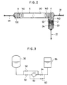
- Fig. 2 is the other embodiment of the present apparatus showing another arrangement thereof
- Fig. 3 shows a pipeline arrangement of the control system of the reservoir tank
- Fig. 4(a) is a cross-sectional view of the baffle structure of a first example
- Fig. 4(b) is a perspective view of the baffle structure of Fig. 4(a)
- Fig. 5(a) is a partial cross-sectional view of the baffle structure of a second example
- Fig. 5(b) is a perspective view of the baffle structure of Fig. 5(a)
- Fig. 6 is an explanatory view of the mechanical booster
- Fig. 7(a) through Fig. 7(c) are explanatory views for explaining the structure and action of the gate valve.
- the reduced pressure swelling and drying apparatus of the present invention has a preparatory heating chamber 2, a food treating chamber 4 under reduced pressure (hereinafter called as “reduced pressure treating chamber") arranged adjacent to the preparatory heating chamber 2, a drying chamber 6 arranged adjacent to the reduced pressure treating chamber 4 and an outlet chamber 8 for taking out the finished dry foods from the apparatus arranged adjacent to the drying chamber 6.
- reduced pressure treating chamber a food treating chamber 4 under reduced pressure
- drying chamber 6 arranged adjacent to the reduced pressure treating chamber 4
- an outlet chamber 8 for taking out the finished dry foods from the apparatus arranged adjacent to the drying chamber 6.
- the transferring direction of the food to be dried is in a straight line not only in the reduced pressure treating chamber 4, the drying chamber 6 and the outlet chamber 8 but also in the preparatory heating chamber 2.
- the preparatory heating chamber 2 has rollers 20 for carrying trays 92 on which the foods to be dried are laid, an air cylinder means 22 for pushing the trays 92 forward, heaters 24 positioned at upper and lower sides of the rollers 20 for heating the foods and a humidifying means 26. Pressure reduction in the preparatory heating chamber 2 is not necessarily required.
- the heater 24 may be an apparatus for radiating electromagnetic waves such as extreme infrared rays or a heating mechanism utilizing microwaves. When utilizing an apparatus for radiating extreme infrared rays, it is preferable to put a plurality of small heat source elements in a side by side relationship or to adopt flat-shaped heat source elements. It is preferable that the heating apparatus has enough capacity to raise the temperature of the ambient atmosphere around the foods to 150 o C and the temperature of the heat source elements to 300 o C.
- the humidifying means 26 may be a water vapor generating apparatus of ultrasonic type and the humidity is controlled by adjusting the opening of a valve 27 or by intermittently opening and closing the valve 27 with a timer (not shown).
- the humidifying means 26 also has a plurality of water vapor nozzles (not shown) for achieving even moistening and water vapor conducting pipes (not shown) are heated for preventing water droplets accumulating on the foods.
- the function of the preparatory heating chamber 2 is to raise the temperature of the foods to be treated and to soften the tissue of the foods to make it possible to rapidly vaporize the water contained in the foods at the following reduced pressure treatment and to increase the degree of swelling of the foods.
- the humidifying means 26 is able to effectively prevent the reduction of swelling efficiency which would be caused in the following reduced pressure treatment if the surfaces of foods are dried.
- the reduced pressure treating chamber 4 has an air cylinder means 31 (for example, as shown in Fig. 2) for pushing the trays 92 forward and a plurality of rollers 32 for sliding the trays 92 and is connected to a reservoir tank 36 through a valve 34.
- the reduced pressure treating chamber 4 is also connected to an oil lubricated type rotary vacuum pump 46 through a parallel pipeline comprising valves 38 and 40 and a control valve 42 and a mechanical booster 44.
- the reservoir tank 36 is connected to another oil lubricated type rotary vacuum pump 48 through a valve 47.
- the reservoir tank 36 is an effective volume variable type which can change the effective volume of the inside space of the tank 36 by changing the volume of oil contained therein. Due to control of the effective volume of the reservoir tank 36, a desired degree of pressure reduction and pressure reduction speed in the chamber 4 can be obtained.
- the reservoir tank 36 is connected to an oil tank 56 through a valve 50, an oil pump 52 and a valve 54.
- a valve 58 is connected to the valve 50 and the oil pump 52 in parallel therewith and a valve 60 is also connected to the oil pump 52 and the valve 54 in parallel therewith.
- the oil pump 52 acts to supply oil in a direction from the valve 50 to the valve 54.
- the range of effective volume variation in the reservoir tank 36 relative to the whole volume of the reduced pressure treating chamber 4 is preferably within 1:70-1:5. However, a range of 1:70-1:20 may be used for normal operation.
- the effective volume of the reservoir tank 36 is increased by operating the oil pump 52 with the valves 50 and 54 opened and simultaneously with the valves 58 and 60 closed. On the contrary, the effective volume of the reservoir tank 36 is reduced by operating the oil pump 52 with the valves 50 and 54 closed simultaneously with the valves 58 and 60 opened.
- a baffle structure 72 or 74 is attached to the reservoir tank 36 at an inlet 70 thereof connected to the valve 34.
- the baffle structure 72 is constructed by multi-stage disc plates 76 in which a plurality of openings are formed and the baffle structure 74 is constructed by a cylindrical member in which a plurality of openings are formed.
- the mechanical booster 44 is composed of a housing 80 and two lobe-shaped rotors 82 rotatably mounted in the housing 80. With the rotation of the rotors 82 in the respective directions of the arrows M and N, the air introduced into an upper side of the housing 80 is exhausted from a lower side thereof.
- the mechanical booster 44 can be operated by a motor of relatively low capacity as compared with an oil lubricating type rotary pump and has a superior exhausting performance especially below 30 torr pressure.
- the drying chamber 6 is composed of a first compartment 84, a second compartment 86 and a third compartment 88 and a conveying means 90 of an endless belt is arranged passing through these compartments 84, 86 and 88.
- a conveying means 90 of an endless belt is arranged passing through these compartments 84, 86 and 88.
- three trays 92 for foods are laid on the upper running portion of the conveying means 90.
- Extreme infrared heaters 94 and 96 are arranged at upper and lower sides of the upper running portion of the conveying means 90 within the compartments 84, 86 and 88.
- a cold trap 104 is connected to the first compartment 84 through a valve 102 and a vacuum pump 108 is also connected to the first compartment 84 through a valve 106.
- the cold trap 104 and the vacuum pump 108 are connected to each other through a valve 110 and a refrigerator 112 is connected to a cooling portion (not shown) of the cold trap 104. Accordingly, the vacuum pump 108 can evacuate the drying chamber 6 through the cold trap 104 or directly, i.e. not through the cold trap 104.
- a control valve 122 is connected to the third compartment 88 through a gas introducing valve 120.
- a gas introducing valve 120 By opening the gas introducing valve 120 and controlling the amount of gas introduction with the control valve 122, it is possible to leak the atmospheric air into the drying chamber 6 so that the pressure in the compartments becomes a desired pressure and it is also possible to expel the water vapor generated from the foods from the drying chamber 6, taking the vapor along with the introduced air stream.
- each reflector 200 may be so formed that it usually closes a passage gate for trays 92 formed at the boundary due to the action of gravity and is displaced by the trays 92 to open the passage gate when the trays 92 pass therethrough.
- the outlet chamber 8 has a plurality of rollers 130 positioned on an extension of the conveying means 90 and is provided with an air cylinder means 131 at a side wall thereof for taking out the trays 92 from the conveying means 90 and is further provided with a lid-closable opening 132 for taking out the trays 92 from the outlet chamber. Since a vacuum pump 136 is connected to the outlet chamber 8 through a valve 134 at a bottom wall thereof, independent evacuation of the outlet chamber 8 is obtainable.
- Gate valves 140 each having the same structure are mounted on each boundary between the preparatory heating chamber 2 and the reduced pressure treating chamber 4, between the reduced pressure treating chamber 4 and the drying chamber 6 and also between the drying chamber 6 and the outlet chamber 8.
- the gate valve 140 is intended to sealingly close each gate 142 and is composed of a driving plate 146 mounted on the extension 144 of the cylinder means and a closing plate 148 movably attached to the driving plate 146.
- the closing plate 148 is connected to the driving plate 146 through links 150 forming a parallelogram link mechanism together with the driving plate 146 and the closing plate 148.
- the closing plate 148 is usually urged toward the driving plate 146 by springs 152.
- the lower end of the closing plate 148 extends beyond the lower end of the driving plate 146 in the urged position of the closing plate 148, as shown in Fig. 7 (a).
- the air cylinder means is so positioned that its extension 144 reciprocates in a vertical plane apart from the gate 142.
- the air cylinder means When the air cylinder means is in a retracted position as shown in Fig. 7(a), the lower end of the closing plate 148 takes a position completely apart from a bottom wall 160 of the chambers and therefore the driving plate 146 and the closing plate 148 are contacted with each other.
- the air cylinder means is extended to a position as shown in Fig. 7(b), the lower end of the closing plate 148 is contacted with the bottom wall 160.
- the closing plate 148 is still in a position apart from the gate 142.
- the gate valve 140 Under such a construction of the gate valve 140, there is a risk that the trays 92 will be crushed by the gate valve 140 if the trays 92 unexpectedly pass near the gate 142 during the closing motion of the gate valve 140.
- an apparatus for detecting the presence of trays 92 such as a photoelectric switch or a limit switch at a region near the gate 142 and for stopping the closing motion of the gate valve 140 when the apparatus detects the presence of trays 92.
- the reduced pressure swelling and drying apparatus of the present invention it is able to continuously manufacture the dried foods by efficiently swelling and drying the raw foods.
- the present invention is able to efficiently evacuate the reduced pressure treating chamber and also to easily and efficiently dry the raw foods in the drying chamber.
- the present invention is able to incorporate the preparatory heating chamber having the heating means and the humidifying means into the pressure reduction means without any trouble and to efficiently carry out the reduced pressure swelling of foods for manufacturing the dried foods of high quality.
Landscapes
- Engineering & Computer Science (AREA)
- Life Sciences & Earth Sciences (AREA)
- Chemical & Material Sciences (AREA)
- Food Science & Technology (AREA)
- Polymers & Plastics (AREA)
- Zoology (AREA)
- Wood Science & Technology (AREA)
- General Engineering & Computer Science (AREA)
- Mechanical Engineering (AREA)
- Molecular Biology (AREA)
- Health & Medical Sciences (AREA)
- Freezing, Cooling And Drying Of Foods (AREA)
- Drying Of Solid Materials (AREA)
- Formation And Processing Of Food Products (AREA)
- Self-Closing Valves And Venting Or Aerating Valves (AREA)
- Grain Derivatives (AREA)
Abstract
Description
- This invention relates to an apparatus for swelling and drying foods under reduced pressure (hereinafter called "a reduced pressure swelling and drying apparatus") and more particularly to a reduced pressure swelling and drying apparatus which can continuously manufacture dried foods such as snack foods having a crispy feeling pleasant to the palate or foods of which the original palete feeling can be restored in a short time by means of boiling water.
- There has been proposed a dried food manufacturing apparatus, for example, such as that disclosed in Japanese Patent Public Disclosure No.120973/1985. This apparatus is so constructed that foods to be dried are introduced into a chamber of reduced pressure and dried by an extreme infrared radiation heating apparatus. However, since a vacuum pump is not arranged in each of an inlet chamber, a drying chamber and an outlet chamber, it is impossible to continuously and effectively carry out the reduced pressure drying treatment of foods.
- In addition, the above mentioned apparatus is so constructed that the water vapor derived from foods is introduced into the vacuum pump by a ventilating fan mounted in the heating apparatus at an upper portion thereof in order to expel the water vapor from the drying chamber. However, since the ventilating fan does not operate when the pressure within the drying chamber is reduced below 50 torr, the vaporizing rate of water contained in foods to be dried is reduced and therefore the drying effect is also lowered.
- There are other known dried food manufacturing apparatuses, for example, such as disclosed in Japanese Patent Public Disclosure Nos.31659/1984, 156272/1984 and 156273/1984. However, all of these apparatuses are formed as batch types and therefore it is impossible to carry out the continuous drying treatment of foods, and they adopt a single-stage pressure reduction system in which a vacuum chamber (a reservoir tank) is connected to the drying chamber. Accordingly, it is impossible to carry out the reduced pressure heating treatment in the drying chamber during evacuation of the vacuum chamber.
- The GB-2071833 discloses a vacuum drying apparatus comprising a vacuum chamber, drying sections and means for creating vacuum. But there is no mention of details of pressure reducing means.
- It is an object of the present invention to provide a reduced pressure swelling and drying apparatus which is able to continuously carry out the reduced pressure drying of foods and to eliminate the above mentioned problems of the prior art.
- It is another object of the present invention to provide a reduced pressure swelling and drying apparatus which is able to effectively carry out the evacuation of the reduced pressure drying chamber.
- It is still another object of the present invention to provide a reduced pressure swelling and drying apparatus which is able to simply and effectively carry out the drying of foods in the drying chamber.
- In order to achieve these objects the invention is based on the following basic ideas.
- Separate pressure reducing means are both connected to a reduced pressure treating chamber and a drying chamber. In this way both chambers can be evacuated independently from each other and to the same vacuum and the transport of the food from the reduced pressure treating chamber into the drying chamber can occur continuously without interruption. Furthermore, two vacuum means: a vacuum pump and a reservoir tank with a vacuum pump are connected in parallel to the reduced pressure treating chamber. In the reduced pressure treating chamber a rapid evacuation with high power is necessary because there is immediate contact with atmospheric pressure after introduction of the food. This is enabled by additionally connecting the reduced pressure treating chamber with the vacuum reservoir causing rapid pressure reduction and rapid swelling of the food by rapid water evaporation.
- Fig. 1 shows one embodiment of the apparatus of the present invention explaining a fundamental principle thereof, Fig. 2 is the other embodiment of the present apparatus showing another arrangement thereof, Fig. 3 shows a pipeline arrangement of the control system of the reservoir tank, Fig. 4(a) is a cross-sectional view of the baffle structure of a first example, Fig. 4(b) is a perspective view of the baffle structure of Fig. 4(a), Fig. 5(a) is a partial cross-sectional view of the baffle structure of a second example, Fig. 5(b) is a perspective view of the baffle structure of Fig. 5(a), Fig. 6 is an explanatory view of the mechanical booster, and Fig. 7(a) through Fig. 7(c) are explanatory views for explaining the structure and action of the gate valve.
- The embodiment of the present invention will now be explained. As shown in Fig. 1, the reduced pressure swelling and drying apparatus of the present invention has a
preparatory heating chamber 2, afood treating chamber 4 under reduced pressure (hereinafter called as "reduced pressure treating chamber") arranged adjacent to thepreparatory heating chamber 2, adrying chamber 6 arranged adjacent to the reducedpressure treating chamber 4 and anoutlet chamber 8 for taking out the finished dry foods from the apparatus arranged adjacent to thedrying chamber 6. According to the embodiment shown in Fig. 1, it is shown that the transferring direction of the food to be dried is in a straight line not only in the reducedpressure treating chamber 4, thedrying chamber 6 and theoutlet chamber 8 but also in thepreparatory heating chamber 2. However, it is preferable to arrange thepreparatory heating chamber 2 so that the transferring direction of the foods passing therethrough crosses perpendicularly to the transferring direction through thechambers - The
preparatory heating chamber 2 hasrollers 20 for carryingtrays 92 on which the foods to be dried are laid, an air cylinder means 22 for pushing thetrays 92 forward,heaters 24 positioned at upper and lower sides of therollers 20 for heating the foods and a humidifyingmeans 26. Pressure reduction in thepreparatory heating chamber 2 is not necessarily required. Theheater 24 may be an apparatus for radiating electromagnetic waves such as extreme infrared rays or a heating mechanism utilizing microwaves. When utilizing an apparatus for radiating extreme infrared rays, it is preferable to put a plurality of small heat source elements in a side by side relationship or to adopt flat-shaped heat source elements. It is preferable that the heating apparatus has enough capacity to raise the temperature of the ambient atmosphere around the foods to 150oC and the temperature of the heat source elements to 300oC. - The humidifying means 26 may be a water vapor generating apparatus of ultrasonic type and the humidity is controlled by adjusting the opening of a
valve 27 or by intermittently opening and closing thevalve 27 with a timer (not shown). The humidifyingmeans 26 also has a plurality of water vapor nozzles (not shown) for achieving even moistening and water vapor conducting pipes (not shown) are heated for preventing water droplets accumulating on the foods. - The function of the
preparatory heating chamber 2 is to raise the temperature of the foods to be treated and to soften the tissue of the foods to make it possible to rapidly vaporize the water contained in the foods at the following reduced pressure treatment and to increase the degree of swelling of the foods. Especially, thehumidifying means 26 is able to effectively prevent the reduction of swelling efficiency which would be caused in the following reduced pressure treatment if the surfaces of foods are dried. - The reduced
pressure treating chamber 4 has an air cylinder means 31 (for example, as shown in Fig. 2) for pushing thetrays 92 forward and a plurality ofrollers 32 for sliding thetrays 92 and is connected to areservoir tank 36 through avalve 34. The reducedpressure treating chamber 4 is also connected to an oil lubricated typerotary vacuum pump 46 through a parallelpipeline comprising valves control valve 42 and amechanical booster 44. Thereservoir tank 36 is connected to another oil lubricated typerotary vacuum pump 48 through avalve 47. - It is possible to carry out a rapid pressure reduction treatment in the reduced
pressure treating chamber 4 by the provision of thereservoir tank 36 and it is also possible to efficiently swell the foods by rapid water evaporation. In addition, it is possible to carry out the pressure reduction at a desired pressure reduction speed without interruption even during preparation for evacuating thereservoir tank 36 and therefore to improve the manufacturing efficiency, since the reducedpressure treating chamber 4 is connected to thevacuum pump 46 through themechanical booster 44. In fact, it is preferable to reduce the pressure in thechamber 4 to lower than 0.1 torr and to so construct thechamber 4 that the pressure therein reaches 0.5 torr within one minute after the connection of thechamber 4 to thereservoir tank 36. - The
reservoir tank 36 is an effective volume variable type which can change the effective volume of the inside space of thetank 36 by changing the volume of oil contained therein. Due to control of the effective volume of thereservoir tank 36, a desired degree of pressure reduction and pressure reduction speed in thechamber 4 can be obtained. As shown in Fig. 3, thereservoir tank 36 is connected to anoil tank 56 through avalve 50, anoil pump 52 and avalve 54. In addition, avalve 58 is connected to thevalve 50 and theoil pump 52 in parallel therewith and avalve 60 is also connected to theoil pump 52 and thevalve 54 in parallel therewith. Theoil pump 52 acts to supply oil in a direction from thevalve 50 to thevalve 54. The range of effective volume variation in thereservoir tank 36 relative to the whole volume of the reducedpressure treating chamber 4 is preferably within 1:70-1:5. However, a range of 1:70-1:20 may be used for normal operation. - The effective volume of the
reservoir tank 36 is increased by operating theoil pump 52 with thevalves valves reservoir tank 36 is reduced by operating theoil pump 52 with thevalves valves - As shown in Figs. 4(a) and (b) and Figs. 5(a) and (b), a
baffle structure reservoir tank 36 at aninlet 70 thereof connected to thevalve 34. Thebaffle structure 72 is constructed bymulti-stage disc plates 76 in which a plurality of openings are formed and thebaffle structure 74 is constructed by a cylindrical member in which a plurality of openings are formed. Thesebaffle structures reservoir tank 36 entering the pipe lines or the reducedpressure treating chamber 4 when the pressure in thechamber 4 is rapidly reduced. Similar effects can be obtained, without the provision of any baffles, by directing the end portion of the evacuating pipe in thereservoir tank 36 away from the oil surface therein. - As shown in Fig. 6, the
mechanical booster 44 is composed of ahousing 80 and two lobe-shaped rotors 82 rotatably mounted in thehousing 80. With the rotation of therotors 82 in the respective directions of the arrows M and N, the air introduced into an upper side of thehousing 80 is exhausted from a lower side thereof. Themechanical booster 44 can be operated by a motor of relatively low capacity as compared with an oil lubricating type rotary pump and has a superior exhausting performance especially below 30 torr pressure. - As shown in Fig. 1, the
drying chamber 6 is composed of afirst compartment 84, asecond compartment 86 and athird compartment 88 and a conveying means 90 of an endless belt is arranged passing through thesecompartments compartments trays 92 for foods are laid on the upper running portion of the conveying means 90. Extremeinfrared heaters compartments - A
cold trap 104 is connected to thefirst compartment 84 through avalve 102 and avacuum pump 108 is also connected to thefirst compartment 84 through avalve 106. Thecold trap 104 and thevacuum pump 108 are connected to each other through avalve 110 and arefrigerator 112 is connected to a cooling portion (not shown) of thecold trap 104. Accordingly, thevacuum pump 108 can evacuate thedrying chamber 6 through thecold trap 104 or directly, i.e. not through thecold trap 104. - A
control valve 122 is connected to thethird compartment 88 through agas introducing valve 120. By opening thegas introducing valve 120 and controlling the amount of gas introduction with thecontrol valve 122, it is possible to leak the atmospheric air into thedrying chamber 6 so that the pressure in the compartments becomes a desired pressure and it is also possible to expel the water vapor generated from the foods from thedrying chamber 6, taking the vapor along with the introduced air stream. - It is preferable, for achieving independent thermal control of each compartment, to provide
reflectors 200 at each boundary between the first andsecond compartments third compartments reflector 200 may be so formed that it usually closes a passage gate fortrays 92 formed at the boundary due to the action of gravity and is displaced by thetrays 92 to open the passage gate when thetrays 92 pass therethrough. - The
outlet chamber 8 has a plurality ofrollers 130 positioned on an extension of the conveyingmeans 90 and is provided with an air cylinder means 131 at a side wall thereof for taking out thetrays 92 from the conveyingmeans 90 and is further provided with a lid-closable opening 132 for taking out thetrays 92 from the outlet chamber. Since avacuum pump 136 is connected to theoutlet chamber 8 through avalve 134 at a bottom wall thereof, independent evacuation of theoutlet chamber 8 is obtainable. -
Gate valves 140 each having the same structure are mounted on each boundary between thepreparatory heating chamber 2 and the reducedpressure treating chamber 4, between the reducedpressure treating chamber 4 and the dryingchamber 6 and also between the dryingchamber 6 and theoutlet chamber 8. As shown in Fig. 7, thegate valve 140 is intended to sealingly close eachgate 142 and is composed of a drivingplate 146 mounted on theextension 144 of the cylinder means and aclosing plate 148 movably attached to the drivingplate 146. Theclosing plate 148 is connected to the drivingplate 146 throughlinks 150 forming a parallelogram link mechanism together with the drivingplate 146 and theclosing plate 148. In addition, theclosing plate 148 is usually urged toward the drivingplate 146 bysprings 152. - The lower end of the
closing plate 148 extends beyond the lower end of the drivingplate 146 in the urged position of theclosing plate 148, as shown in Fig. 7 (a). The air cylinder means is so positioned that itsextension 144 reciprocates in a vertical plane apart from thegate 142. When the air cylinder means is in a retracted position as shown in Fig. 7(a), the lower end of theclosing plate 148 takes a position completely apart from abottom wall 160 of the chambers and therefore the drivingplate 146 and theclosing plate 148 are contacted with each other. Then, when the air cylinder means is extended to a position as shown in Fig. 7(b), the lower end of theclosing plate 148 is contacted with thebottom wall 160. However, theclosing plate 148 is still in a position apart from thegate 142. - Finally, when the air cylinder means is extended to its maximum extended position as shown in Fig. 7(c), not only the lower end of the
closing plate 148 but also the lower end of the drivingplate 146 contact with thebottom wall 160, and therefore thelinks 150 are moved toward a horizontal position against the urging force of thesprings 152. Thus, theclosing plate 148 is completely pressed against thegate 142 and tightly closes thegate 142. - Under such a construction of the
gate valve 140, there is a risk that thetrays 92 will be crushed by thegate valve 140 if thetrays 92 unexpectedly pass near thegate 142 during the closing motion of thegate valve 140. In order to avoid this problem, it is preferable to arrange an apparatus for detecting the presence oftrays 92 such as a photoelectric switch or a limit switch at a region near thegate 142 and for stopping the closing motion of thegate valve 140 when the apparatus detects the presence oftrays 92. - In addition, there is a risk that the foods in the chambers will be blown off if the
gate valve 140 is opened while there is a large pressure difference between mutually adjacent chambers, since the thermal control and the pressure control in thepreparatory heating chamber 2, the reducedpressure treating chamber 4, the dryingchamber 6 and theoutlet chamber 8 are carried out independently. In order to avoid this problem, it is preferable to so control thegate valve 140 that it stops its opening motion when a pressure difference exceeding a predetermined value between mutually adjacent chambers is detected by a pressure difference detecting apparatus arranged in the chambers. - According to the reduced pressure swelling and drying apparatus of the present invention, it is able to continuously manufacture the dried foods by efficiently swelling and drying the raw foods.
- Furthermore, according to the present invention, it is able to efficiently evacuate the reduced pressure treating chamber and also to easily and efficiently dry the raw foods in the drying chamber.
- Still furthermore, according to the present invention, it is able to incorporate the preparatory heating chamber having the heating means and the humidifying means into the pressure reduction means without any trouble and to efficiently carry out the reduced pressure swelling of foods for manufacturing the dried foods of high quality.
Claims (4)
- An apparatus for swelling and drying foods under reduced pressure comprising a reduced pressure treating chamber (4) connected to a first vacuum pump (46) and, in parallel thereto, a reservoir tank (36) wherein the reservoir tank (36) is connected to second vacuum pump (48), a drying chamber (6) having a pressure reducing means (102, 104, 106, 108, 110, 112), a heating means (94, 96) and a conveying means (90), and an outlet chamber (8) having a pressure reducing means (134, 136), the reduced pressure treating chamber (4), the drying chamber (6) and the outlet chamber (8) being continuously arranged in this order.
- The apparatus as defined in claim 1, wherein said heating means (94,96) is an electromagnetic wave radiating apparatus.
- The apparatus as defined in claim 1, wherein said reduced pressure treating chamber (4) and said drying chamber (6) as well as said drying chamber (6) and said outlet chamber (8) are connected to each other through gate valves (140).
- The apparatus as defined in claim 1, wherein said drying chamber (6) has a gas introducing means (120, 122).
Applications Claiming Priority (2)
| Application Number | Priority Date | Filing Date | Title |
|---|---|---|---|
| JP282349/85 | 1985-12-16 | ||
| JP60282349A JPH06101999B2 (en) | 1985-12-16 | 1985-12-16 | Vacuum expansion and drying device |
Publications (3)
| Publication Number | Publication Date |
|---|---|
| EP0252155A1 EP0252155A1 (en) | 1988-01-13 |
| EP0252155A4 EP0252155A4 (en) | 1989-11-07 |
| EP0252155B1 true EP0252155B1 (en) | 1993-10-06 |
Family
ID=17651256
Family Applications (1)
| Application Number | Title | Priority Date | Filing Date |
|---|---|---|---|
| EP87900266A Expired - Lifetime EP0252155B1 (en) | 1985-12-16 | 1986-12-16 | Depressurizing, swelling and drying apparatus |
Country Status (8)
| Country | Link |
|---|---|
| US (1) | US4809596A (en) |
| EP (1) | EP0252155B1 (en) |
| JP (1) | JPH06101999B2 (en) |
| KR (1) | KR900003729B1 (en) |
| AU (1) | AU602666B2 (en) |
| DE (1) | DE3689150T2 (en) |
| DK (1) | DK422087A (en) |
| WO (1) | WO1987003455A1 (en) |
Families Citing this family (25)
| Publication number | Priority date | Publication date | Assignee | Title |
|---|---|---|---|---|
| FR2635644B1 (en) * | 1988-08-30 | 1991-11-08 | Bournier Edgard | PROCESS AND DEVICE FOR REDUCING LOSSES IN CONSTITUENT ELEMENTS OF VEGETABLES AND IN PARTICULAR MUSHROOMS DURING THEIR CANNING FOR APPERTISATION, FREEZING, BROILING |
| US4955289A (en) * | 1988-12-09 | 1990-09-11 | Shohei Eguchi | Tea leaves firing equipment |
| DE4010594C2 (en) * | 1990-04-02 | 1998-11-19 | Bucher Guyer Ag | Process for drying lumpy, organic products |
| US5334402A (en) * | 1990-08-03 | 1994-08-02 | Kansas State University Research Foundation | Heat processing of a product |
| EP0607127A1 (en) * | 1990-08-03 | 1994-07-27 | Kansas State University Research Foundation | Heat processing of a product |
| WO1992022365A2 (en) * | 1991-06-11 | 1992-12-23 | Hak-Anlagenbau Gmbh Für Verfahrenstechnik, Strahlulngstechnik Und Trocknungstechnik | Process for removing evaporable substances and installation for implementing the process |
| US5184538A (en) * | 1992-05-26 | 1993-02-09 | The Laitram Corporation | High efficiency steam cooker |
| US5676989A (en) * | 1996-03-29 | 1997-10-14 | The University Of British Columbia | Production of chips |
| DE19721707C2 (en) * | 1997-05-23 | 1999-04-01 | Becker Preservotec Gmbh | Process for drying paper |
| FR2768026B1 (en) * | 1997-09-09 | 1999-12-03 | Soc D Dev Ind Agro Alimentaire | PROCESS AND PLANT FOR DEHYDRATION OF A FOOD PRODUCT AS WELL AS THE DEHYDRATED FOOD OBTAINED |
| FR2774911B1 (en) * | 1998-02-19 | 2005-01-14 | Karim Allaf | PROCESS FOR THE THERMAL, THERMO-MECHANICAL, HYDRO-THERMO-MECHANICAL TREATMENT OF MISCELLANEOUS SOLID OR PULVERULENT PRODUCTS, PASTA, LIQUIDS OR MIXTURES OF LIQUIDS, APPLICATIONS THEREOF |
| DE10153944C1 (en) * | 2001-11-06 | 2003-01-02 | Linn High Therm Gmbh | Microwave through-flow oven has entry opening closed by door with lamella elements pressed against U-shaped profile frame around outside of opening via elongate pressure elements |
| US20030211207A1 (en) * | 2002-05-07 | 2003-11-13 | Newman Michael D. | Apparatus and method for providing treatment to a continuous supply of food product using a vacuum process |
| ITTV20020120A1 (en) | 2002-10-18 | 2004-04-19 | S M C Srl | TUNNEL FOR THE CONDITIONING OF FOOD PRODUCTS |
| US20050112255A1 (en) * | 2003-11-25 | 2005-05-26 | Tottenham Dennis E. | Apparatus and method for microbial intervention and pasteurization of food and equipment |
| JP2006129822A (en) * | 2004-11-09 | 2006-05-25 | Miura Co Ltd | Vacuum cooling machine |
| KR100799369B1 (en) * | 2007-06-28 | 2008-01-30 | 박종래 | Bulging device |
| NZ584266A (en) * | 2007-10-15 | 2012-01-12 | Enwave Corp | Apparatus for microwave vacuum-drying of organic materials including means for moving a rotating container through a vacuum chamber |
| CA2927434C (en) | 2013-10-16 | 2022-07-19 | Merck Sharp & Dohme Corp. | Method of obtaining thermostable dried vaccine formulations |
| EP3057978B1 (en) | 2013-10-16 | 2022-09-14 | Merck Sharp & Dohme LLC | Method of microwave vacuum drying spherical-shaped pellets of biological materials |
| US10369213B2 (en) | 2013-10-16 | 2019-08-06 | Merck Sharp & Dohme Corp. | Thermostable respiratory synctial virus (RSV) vaccine compositions |
| JP6836893B2 (en) * | 2016-12-16 | 2021-03-03 | アルバック九州株式会社 | Porous dried food manufacturing method and porous dried food manufacturing equipment |
| KR101975598B1 (en) | 2018-08-21 | 2019-05-07 | 차경우 | Propeller device for a vessel |
| US11166469B1 (en) * | 2020-05-08 | 2021-11-09 | Crunch Food, Inc. | System and method for preparing an edible multilayer food carrier |
| EP4161690A4 (en) * | 2020-06-05 | 2024-06-19 | Merck Sharp & Dohme LLC | Apparatus and method of microwave vacuum drying sterile products |
Family Cites Families (10)
| Publication number | Priority date | Publication date | Assignee | Title |
|---|---|---|---|---|
| US2846319A (en) * | 1955-07-26 | 1958-08-05 | E J Kelly & Associates Inc | Drying process |
| US4045639A (en) * | 1973-01-16 | 1977-08-30 | Food Processing Systems Corporation | Continuous microwave and vacuum dryer |
| US3969183A (en) * | 1974-10-04 | 1976-07-13 | A. E. Staley Manufacturing Company | Vacuum dehydration of heat sensitive materials |
| US3970764A (en) * | 1974-12-27 | 1976-07-20 | Dravo Corporation | Process for preparing a protein concentrate with minimal protein denaturation |
| US4006260A (en) * | 1975-01-29 | 1977-02-01 | Wells A. Webb | Method and apparatus for evaporation of moisture from fruit and vegetable particles |
| JPS591941B2 (en) * | 1975-04-01 | 1984-01-14 | 日本合成化学工業株式会社 | Drying method of saponified ethylene-vinyl acetate copolymer particles |
| GB2071833B (en) * | 1980-02-05 | 1984-07-11 | Balfour & Co Ltd Henry | Vacuum drying apparatus |
| US4520574A (en) * | 1983-02-25 | 1985-06-04 | House Food Industrial Co., Ltd. | Process for drying foods under reduced pressure |
| JPS60120973A (en) * | 1983-12-02 | 1985-06-28 | Riyouhan Hoso Syst Kk | Drying of food with far infrared radiation under reduced pressure |
| JPS60234836A (en) * | 1984-05-09 | 1985-11-21 | 昭和電工株式会社 | Dehydration and water retention sheet |
-
1985
- 1985-12-16 JP JP60282349A patent/JPH06101999B2/en not_active Expired - Lifetime
-
1986
- 1986-12-16 DE DE87900266T patent/DE3689150T2/en not_active Expired - Fee Related
- 1986-12-16 EP EP87900266A patent/EP0252155B1/en not_active Expired - Lifetime
- 1986-12-16 US US07/086,629 patent/US4809596A/en not_active Expired - Lifetime
- 1986-12-16 WO PCT/JP1986/000635 patent/WO1987003455A1/en active IP Right Grant
- 1986-12-16 AU AU67367/87A patent/AU602666B2/en not_active Ceased
- 1986-12-16 KR KR1019870700732A patent/KR900003729B1/en not_active IP Right Cessation
-
1987
- 1987-08-13 DK DK422087A patent/DK422087A/en not_active Application Discontinuation
Also Published As
| Publication number | Publication date |
|---|---|
| EP0252155A4 (en) | 1989-11-07 |
| US4809596A (en) | 1989-03-07 |
| DE3689150T2 (en) | 1994-02-03 |
| KR880700642A (en) | 1988-04-11 |
| KR900003729B1 (en) | 1990-05-30 |
| JPS62143674A (en) | 1987-06-26 |
| DK422087D0 (en) | 1987-08-13 |
| JPH06101999B2 (en) | 1994-12-14 |
| WO1987003455A1 (en) | 1987-06-18 |
| DE3689150D1 (en) | 1993-11-11 |
| EP0252155A1 (en) | 1988-01-13 |
| AU602666B2 (en) | 1990-10-25 |
| AU6736787A (en) | 1987-06-30 |
| DK422087A (en) | 1987-08-13 |
Similar Documents
| Publication | Publication Date | Title |
|---|---|---|
| EP0252155B1 (en) | Depressurizing, swelling and drying apparatus | |
| EP0676028B1 (en) | Apparatus for gas treatment of products | |
| US6455826B1 (en) | Apparatus and method for continuous microwave drying of ceramics | |
| RU2236655C2 (en) | Apparatus for gas treatment of products | |
| US6035764A (en) | Rice processing apparatus with continuously steaming and boiling | |
| US6056986A (en) | Method and apparatus for continuously steaming and boiling rice | |
| JP7596520B2 (en) | Food freezing equipment and food processing system | |
| KR102335863B1 (en) | Continuous hybird drying system for agricultural and fishery products | |
| KR102436477B1 (en) | Food steaming apparatus and food processing system | |
| CN111551008B (en) | A microwave vacuum drying equipment | |
| CN108669526A (en) | A kind of energy saving bean sheet jelly production line | |
| JP3472475B2 (en) | Thawing device | |
| CA1210287A (en) | Heating process and its apparatus in reducing air pressure within a chamber at a balanced level | |
| CN212501382U (en) | Shrinkage furnace for bagging machine | |
| CN115560574A (en) | Rhizome class traditional chinese medicine drying equipment | |
| CN210425774U (en) | Vacuum drying equipment | |
| RU2059952C1 (en) | Drier | |
| JPH0217796B2 (en) | ||
| JP2802750B2 (en) | Vacuum drying equipment | |
| CN2078429U (en) | Dryer by steamed far infra-red ray hot plate | |
| JPS6316672B2 (en) | ||
| JP2020156595A (en) | Continuous steamer | |
| RU2077251C1 (en) | Frying-drying chamber | |
| CN115790132A (en) | Seaweed superheated steam blanching device and method and seaweed superheated steam drying system | |
| JPH01127886A (en) | Decompression dehumidifying drier |
Legal Events
| Date | Code | Title | Description |
|---|---|---|---|
| PUAI | Public reference made under article 153(3) epc to a published international application that has entered the european phase |
Free format text: ORIGINAL CODE: 0009012 |
|
| 17P | Request for examination filed |
Effective date: 19871023 |
|
| AK | Designated contracting states |
Kind code of ref document: A1 Designated state(s): CH DE FR GB IT LI NL SE |
|
| A4 | Supplementary search report drawn up and despatched |
Effective date: 19891107 |
|
| 17Q | First examination report despatched |
Effective date: 19911016 |
|
| GRAA | (expected) grant |
Free format text: ORIGINAL CODE: 0009210 |
|
| ITF | It: translation for a ep patent filed | ||
| AK | Designated contracting states |
Kind code of ref document: B1 Designated state(s): CH DE FR GB IT LI NL SE |
|
| REF | Corresponds to: |
Ref document number: 3689150 Country of ref document: DE Date of ref document: 19931111 |
|
| ET | Fr: translation filed | ||
| PLBE | No opposition filed within time limit |
Free format text: ORIGINAL CODE: 0009261 |
|
| STAA | Information on the status of an ep patent application or granted ep patent |
Free format text: STATUS: NO OPPOSITION FILED WITHIN TIME LIMIT |
|
| 26N | No opposition filed | ||
| EAL | Se: european patent in force in sweden |
Ref document number: 87900266.5 |
|
| PGFP | Annual fee paid to national office [announced via postgrant information from national office to epo] |
Ref country code: FR Payment date: 20001020 Year of fee payment: 15 |
|
| PGFP | Annual fee paid to national office [announced via postgrant information from national office to epo] |
Ref country code: SE Payment date: 20001102 Year of fee payment: 15 |
|
| PGFP | Annual fee paid to national office [announced via postgrant information from national office to epo] |
Ref country code: GB Payment date: 20001208 Year of fee payment: 15 |
|
| PGFP | Annual fee paid to national office [announced via postgrant information from national office to epo] |
Ref country code: NL Payment date: 20001231 Year of fee payment: 15 |
|
| PGFP | Annual fee paid to national office [announced via postgrant information from national office to epo] |
Ref country code: DE Payment date: 20010228 Year of fee payment: 15 |
|
| PGFP | Annual fee paid to national office [announced via postgrant information from national office to epo] |
Ref country code: CH Payment date: 20010308 Year of fee payment: 15 |
|
| PG25 | Lapsed in a contracting state [announced via postgrant information from national office to epo] |
Ref country code: GB Free format text: LAPSE BECAUSE OF NON-PAYMENT OF DUE FEES Effective date: 20011216 |
|
| PG25 | Lapsed in a contracting state [announced via postgrant information from national office to epo] |
Ref country code: SE Free format text: LAPSE BECAUSE OF NON-PAYMENT OF DUE FEES Effective date: 20011217 |
|
| PG25 | Lapsed in a contracting state [announced via postgrant information from national office to epo] |
Ref country code: LI Free format text: LAPSE BECAUSE OF NON-PAYMENT OF DUE FEES Effective date: 20011231 Ref country code: CH Free format text: LAPSE BECAUSE OF NON-PAYMENT OF DUE FEES Effective date: 20011231 |
|
| REG | Reference to a national code |
Ref country code: GB Ref legal event code: IF02 |
|
| PG25 | Lapsed in a contracting state [announced via postgrant information from national office to epo] |
Ref country code: NL Free format text: LAPSE BECAUSE OF NON-PAYMENT OF DUE FEES Effective date: 20020701 |
|
| PG25 | Lapsed in a contracting state [announced via postgrant information from national office to epo] |
Ref country code: DE Free format text: LAPSE BECAUSE OF NON-PAYMENT OF DUE FEES Effective date: 20020702 |
|
| EUG | Se: european patent has lapsed |
Ref document number: 87900266.5 |
|
| GBPC | Gb: european patent ceased through non-payment of renewal fee |
Effective date: 20011216 |
|
| REG | Reference to a national code |
Ref country code: CH Ref legal event code: PL |
|
| PG25 | Lapsed in a contracting state [announced via postgrant information from national office to epo] |
Ref country code: FR Free format text: LAPSE BECAUSE OF NON-PAYMENT OF DUE FEES Effective date: 20020830 |
|
| NLV4 | Nl: lapsed or anulled due to non-payment of the annual fee |
Effective date: 20020701 |
|
| REG | Reference to a national code |
Ref country code: FR Ref legal event code: ST |
|
| PG25 | Lapsed in a contracting state [announced via postgrant information from national office to epo] |
Ref country code: IT Free format text: LAPSE BECAUSE OF NON-PAYMENT OF DUE FEES Effective date: 20051216 |