EP0252032A2 - System zum Antrieb und zur Regelung bzw. Steuerung einer periodisch (selbstregelnd) arbeitenden Spinnmaschine - Google Patents
System zum Antrieb und zur Regelung bzw. Steuerung einer periodisch (selbstregelnd) arbeitenden Spinnmaschine Download PDFInfo
- Publication number
- EP0252032A2 EP0252032A2 EP87830253A EP87830253A EP0252032A2 EP 0252032 A2 EP0252032 A2 EP 0252032A2 EP 87830253 A EP87830253 A EP 87830253A EP 87830253 A EP87830253 A EP 87830253A EP 0252032 A2 EP0252032 A2 EP 0252032A2
- Authority
- EP
- European Patent Office
- Prior art keywords
- actuation
- rod
- spindles
- bench
- cylinders
- Prior art date
- Legal status (The legal status is an assumption and is not a legal conclusion. Google has not performed a legal analysis and makes no representation as to the accuracy of the status listed.)
- Granted
Links
Images
Classifications
-
- D—TEXTILES; PAPER
- D01—NATURAL OR MAN-MADE THREADS OR FIBRES; SPINNING
- D01H—SPINNING OR TWISTING
- D01H3/00—Spinning or twisting machines in which the product is wound-up intermittently, e.g. mules
- D01H3/02—Details
- D01H3/26—Driving or stopping arrangements not otherwise provided for; Locking motions ; Control of machines
-
- D—TEXTILES; PAPER
- D01—NATURAL OR MAN-MADE THREADS OR FIBRES; SPINNING
- D01H—SPINNING OR TWISTING
- D01H3/00—Spinning or twisting machines in which the product is wound-up intermittently, e.g. mules
Definitions
- the motion of the main members of the spinner is generally effected by means of three electrical motors: a main motor for the actuation of the spindles; a second motor which operates - through mechanical connections - the pirns-holder bench (and/or the spindles-holder bench), the cylinders and the feeding drum, the group for the actuation of the rod and counter-rod; a third electrical motor - possibly double-acting - which drives the rod and the counter-rod rotation, during the subwinding phase at the end of the spindle take-up.
- the various phases performed by the above mentioned actuation means are synchronized by electronic and electro-mechanical equipment.
- the positioning of the winding rod at the beginning of the needleful winding is driven, for example, by a pneumatic piston.
- independent actuation means are known from the prior art, having variable-speed motors, for the shaft of relative displacement between the pirns-holder bench and the spindles-holder bench, and for the shaft which operates the feeding cylinders.
- connections and transmissions of generally mechanical type are employed, mostly adjustable with the machine being at a standstill.
- the present invention refers to a system for the actuation and control of a selfacting spinner, capable of simplfying the mechanics, rationalizing the controls and sequences, reducing dead times and improving the product features.
- a system for the usage of a central processing unit (CPU), which receives and process the information relative to the process execution and, in particular, controls and co-ordinates a number of motors and/or actuators, to individually obtain all the motions - translations and rotations that may be even partial - needed for carrying out the whole operation cycle, that is: A - the spindles rotation; B - The relative displacement between the pirns-holder bench and the spindles-holder bench; C - the rotation of the cylinders; D - the rotation of the pirns-unwinding drum for the feeding; E - the actuation of the winding rod; F - the actuation of the counter-rod.
- CPU central processing unit
- a simplification and/or replacement of electro-mechanical driving and synchronization members is thus obtained, among other things, by making use of individual actuation means (variable-speed or other kind of electrical motors), each of them being piloted by a microprocessor unit.
- the actuation system in question may comprise a central microprocessor unit and individual peripheral adjustment modules for one or more of members: for the actuation of the spindles; for the actuation of the mobile bench (spindles and/or feeding bench); for the actuation of cylinders; for the actuation of the rove feeding, for the actuation of the winding rod; for the actuation of the counter-rod.
- Transducers are provided for picking up the information relative to the instantaneous conditions reached by various members.
- the actuation system in question may also comprise optical sight or similar controlling means, for the disposition of the bays of material which is fed to the cylinders and for the consequent corrections.
- the actuation members are provided with variable speed - mostly step-by-step and/or variable-speed electrical motors like d.c. motors or other -.
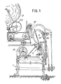
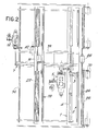
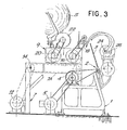
- numeral 1 indicates the structure for a bench 2 - stationary in the example - of the spindles 3, arranged in a row with inclined axes; the spindles 3 are suitably driven, for example by a motor 5, via suitable transmissions, or by individual motors.
- Numeral 7 indicates a fixed structure forming tracks 7A for the to-and-fro movements of a carriage structure 9 forming the pirns-holder bench for the pirns or beams S;
- numeral 12 indicates a motorization for a shaft 14 for the movement of group 9.
- Said group 9 carries a motorization 16 which drives the shaft of the cylinders 18 of a set of cylinders as well as a motorization 20 for a cylinder 22 intended to feed the material of the pirns or beams S, which rest on said cylinder 22, to the cylinders 18.
- a motorization 16 which drives the shaft of the cylinders 18 of a set of cylinders as well as a motorization 20 for a cylinder 22 intended to feed the material of the pirns or beams S, which rest on said cylinder 22, to the cylinders 18.
- shafts 24 and 26 are also provided, respectively of the winding rod and of the counter-rod, respectively operated by motors 28 and 30.
- the present invention provides for the direct actuation of the above defined shafts 4, 14, 18, 22, 24, 26.
- the individual actuations may be carried out by utilizing, on each shaft, one or several electrical motors or motor reducers at variable speed like the ones above mentioned (step-by-step motors or other kind of actuation means) and like those herein illustrated, driven through suitable adjustment and control modules by a microprocessor central unit which is interfaced to input/output peripheral units or devices for data entry and control of the system by the operator.
- Substantially the motions of the above mentioned shafts perform the spinning cycle steps: feeding; draft; twist; breaking off or snipping; binding and winding and the subwinding phase at the end of the spindle take-up.
- These motions are imparted, coordinated and controlled by the microprocessor central unit, which may pass certain functions - according to the circumnstances - to other processors.
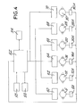
- Fig. 4 the structure of the system is shown in Fig. 4 in a block diagram form.
- the cards are connected for setting the motors, the input/output peripheral units (keyboard, video unit, printer, etc.), the store modules and the transducers which detect the shaft movements; store units are indicated by 54, parameter-insertion units by 56, output units (video, printer) by 58.
- the system of Fig. 4 may comprise a single microprocessor, in which case the data processing is concentrated on the central unit 52, or a central microprocessor 52 and other processors which lead to adjustment cards or modules 60, 62, 64, 66, 68, 70. In this case the processing tasks are divided between the central unit and the other processors.
- Each adjustment module is generally able to actuate and/or control one or more shafts and hold one or more processors.
- an operating version - always with reference to Fig. 4 - may provide that the central unit 52 performs the operations in sequence and the adjustment modules perform the adjustment of the individual actuation means.
- module 60 controls motor 5 of spindles
- module 62 controls motor 12 of the bench
- module 64 controls motor 16 of cylinders
- module 66 controls motor 20 of the feeding
- module 68 controls motor 28 for the winding rod
- module 70 controls motors 30 for the counter-rod.
- 5A, 12A, 16A, 20A, 28A and 30A the transducers are indicated being associated to the individual control motors or members to supply return data to the microprocessor 52 and/or to the pertinent processors.
- the adjustments of the spindles, bench, cylinders, feeding, winding rod may also be made in terms of speed or position.
- the actuation of the counter-rod takes place, instead, by regulating the torque.
- the working data and parameters in digital form, can be entered from a keyboard located on the machine or from a linked remote computer; in any case these data are stored on data supports.
- the working parameters and the monitoring of the machine may be supplied on the machine video and/or printer, or obtained from a remote computer.
- the motion of either the pirns-holder bench or spindles-holder bench or of both these benches simultaneously, during the feeding operation, through the shaft 14, is controlled - via software - to permit the adjustment of the variable speed of the bench and of the breaking and acceleration parameters both upon the feed and draft phase, and upon the winding and the bench re-entry, and the variation of the needleful length possibly through the consequent automatic adjustment of the acceleration and breaking parameters.
- This allows the working parameters to be optimized with consequent improvement of the yarn quality, with respect to what is provided by the existing machines, wherein mechanical devices are provided which allow discrete and little flexibility adjustments to be made while the length of the needleful, that is, the bench run is generally fixed, or can be varied, through complex mechanical modifications.
- the synchronization of the feedings between the drum 22 and the cylinders 18, that is, between the groups driven by motors 16 and 20, may also be optimized.
- the control of the cylinders is derived from the mobile bench movement through a mechanical transmission (chain or the like) which ensures also the perfect synchronism; the feeding drum is actuated by the cylinders shaft, and the peripheral speed thereof, with respect to that of cylinders, is now adjusted by hand through a mechanical variator and, usually, at each change of the lot of material.
- this invention it is possible to perform this adjustment through the keyboard, or resist the speed ratios (stored values), utilized in previous workings of similar material, with significant regulation and variation elasticity, even during the working phase.
- an automated control of the synchronization between the drum 22 and the cylinders 18 is realized by means of sights - especially optical sights - by which it is possible to evaluate the arrangement of the mean bay of the roves between the drum 22 and the cylinders 18 in order to control, in one direction or the other, the peripheral speed of the drum in order to correct said arrangement so as to keep it between the two sights.
- the prior systems during the output phase of the bench or benches, allow to obtain step-by-step adjustments among three draft conditions; by operating the two electro-mechanical clutches held in the machine head it is possible to obtain: nul draft, partial draft according to predetermined transmission ratios, and total draft.
- the entry of the draft parameters from the keyboard allows determined draft functions to be anyway combined and the values and extension thereof to be adjusted up to cover the whole length of the needleful (draft and counts data relative to the rove and the yarn).
- several suitably classified configurations may be programmed, that can be recalled through the keyboard by means of codes.
- it is possible to program the draft function from the keyboard by supplying draft data in a discrete number of points along the bench run and supplying the work parameters (input and output counts, number of twists inserted, etc.).
- a correction factor possibly allows to automatically adjust the total draft and the count.
- both the spindles rotation imparted to the relevant motor, and the rod motion derived, according to this invention, from the proper variable-speed motor 28, are committed to the central unit; the motor 28 is capable of carrying out, in addition to this snipping phase, also the remaining movements of the rod 24 during the successive winding phase, as well as during the subwinding phase.
- the machines now present on the market utilize, in general, mechanical systems which do not permit the spool formation parameters to be varied but through complex modifications.
- the cone-forming turns are distributed on the spools according to a rod motion which is defined by the profile of a stick (that is pipe) or "core"; the speed of the spindles has to compensate for the radius variation of the spool winding and the speed variations of the mobile bench(es).
- the variation of the spindle speed on the machines of present-day is controlled by the so-called sector - mostly electronic or the like - piloted by an encoder located on the counter-rod.
- the function of controlling the spindles speed during the winding may be committed to the central unit by detecting the counter-rod position signal.
- the flexible, computerized and independent operation of the motion parameters of the spindles, of the bench and of the rod allows different and thus more suitable shapes of spools to be achieved (conical, cylindrical, and other shapes), and also the multi-layer spool taper and shape to be easily modified.
- the system according to the invention permits to determine both the displacement law of the rod (by adjusting the increase of the starting point of the winding during the spindle take-up), and the turns distributing during the winding.
- the functions of the counter-rod remain those of adjusting the yarn tension and recovering the same yarn during the breaking off or snipping.
- the counter-rod may be actuated in such a way as to limit and/or compensate also for the torsional deformations.
- the counter-rod operation is committed to a plurality of variable-speed electrical motors, distributed along the machine front as to limit the torsional deformations and make the spool formation uniform in the various spindles; in this way, the known drawbacks that can be found on the machines of present-day are reduced or eliminated and also the differences in the compactness of the spool between the start and end point of the spindles take-up are, at least in part, narrowed.
- the regulation of said motors is made by keeping the torque constant, that is, by continuously regulating - during the spindle take-up - the tension of the yarn.
- the winding rod may be operated by one or several motors so as to reduce - also in this case - the torsional deformations and optimize the spool formation.
- the re-entry of the bench is achieved, in the example of the drawing, by the shaft 14 and the motor 12.
- the lightenings of the bench facilitate the movements thereof while improving the machine performance.
- one or several electrical motors are utilized for the simultaneous actuation of the rod and counter-rod by means of a mechanical device; the rod is so positioned as to wind the yarn under the tube, while the counter-rod is positioned at middle height.
- independent actuation means - with the programm operable according to the invention - on said two shafts, allows the actuation means relative to the shafts 24 and 26 to be driven during the subwinding phase by recalling suitable subroutines.
Landscapes
- Engineering & Computer Science (AREA)
- Mechanical Engineering (AREA)
- Textile Engineering (AREA)
- Spinning Or Twisting Of Yarns (AREA)
Applications Claiming Priority (2)
| Application Number | Priority Date | Filing Date | Title |
|---|---|---|---|
| IT943086 | 1986-07-04 | ||
| IT8609430A IT1216234B (it) | 1986-07-04 | 1986-07-04 | Sistema per l'azionamento ed il controllo di un filatoio intermittente (selfacting). |
Publications (3)
| Publication Number | Publication Date |
|---|---|
| EP0252032A2 true EP0252032A2 (de) | 1988-01-07 |
| EP0252032A3 EP0252032A3 (en) | 1988-02-24 |
| EP0252032B1 EP0252032B1 (de) | 1991-01-09 |
Family
ID=11130038
Family Applications (1)
| Application Number | Title | Priority Date | Filing Date |
|---|---|---|---|
| EP87830253A Expired EP0252032B1 (de) | 1986-07-04 | 1987-07-02 | System zum Antrieb und zur Regelung bzw. Steuerung einer periodisch (selbstregelnd) arbeitenden Spinnmaschine |
Country Status (4)
| Country | Link |
|---|---|
| EP (1) | EP0252032B1 (de) |
| JP (1) | JP2529272B2 (de) |
| DE (1) | DE3767233D1 (de) |
| IT (1) | IT1216234B (de) |
Cited By (1)
| Publication number | Priority date | Publication date | Assignee | Title |
|---|---|---|---|---|
| EP1728901A3 (de) * | 2005-05-31 | 2007-10-31 | Proxima Srl | Wagenspinnmaschine |
Families Citing this family (1)
| Publication number | Priority date | Publication date | Assignee | Title |
|---|---|---|---|---|
| CN103409859B (zh) * | 2013-08-13 | 2015-09-30 | 青岛环球集团股份有限公司 | 兼具纺纱与落纱功能的粗纱机的传动机构 |
Family Cites Families (4)
| Publication number | Priority date | Publication date | Assignee | Title |
|---|---|---|---|---|
| GB732665A (en) * | 1952-01-28 | 1955-06-29 | Tmm Research Ltd | Improvements in and relating to spinning mules |
| GB1374767A (en) * | 1971-01-29 | 1974-11-20 | Ici Ltd | Polyamides |
| JPS5216156B2 (de) * | 1972-08-16 | 1977-05-07 | ||
| JPS5136380A (en) * | 1974-09-20 | 1976-03-27 | Tachibana Seisakusho Kk | Kosokujutenhoho oyobi sochi |
-
1986
- 1986-07-04 IT IT8609430A patent/IT1216234B/it active
-
1987
- 1987-07-02 EP EP87830253A patent/EP0252032B1/de not_active Expired
- 1987-07-02 DE DE8787830253T patent/DE3767233D1/de not_active Expired - Fee Related
- 1987-07-03 JP JP62165581A patent/JP2529272B2/ja not_active Expired - Lifetime
Cited By (2)
| Publication number | Priority date | Publication date | Assignee | Title |
|---|---|---|---|---|
| EP1728901A3 (de) * | 2005-05-31 | 2007-10-31 | Proxima Srl | Wagenspinnmaschine |
| CN1873066B (zh) * | 2005-05-31 | 2010-09-29 | 比邻星有限公司 | 自动纺纱机 |
Also Published As
| Publication number | Publication date |
|---|---|
| JPS63145429A (ja) | 1988-06-17 |
| IT8609430A0 (it) | 1986-07-04 |
| EP0252032A3 (en) | 1988-02-24 |
| DE3767233D1 (de) | 1991-02-14 |
| JP2529272B2 (ja) | 1996-08-28 |
| EP0252032B1 (de) | 1991-01-09 |
| IT1216234B (it) | 1990-02-22 |
Similar Documents
| Publication | Publication Date | Title |
|---|---|---|
| CN101372775B (zh) | 生产交叉卷绕筒子的纺织机 | |
| EP0375480A2 (de) | Elektronisch gesteuerte Musterzettelmaschine | |
| JP3989948B1 (ja) | 複数ワイヤ同時巻線方法及びその巻線装置 | |
| CA2717330A1 (en) | Ring spinning mechanism with fixed ring location | |
| EP0461524B1 (de) | Schussfadenzubringvorrichtung für Greiferwebmaschinen | |
| EP1411015A2 (de) | Fadenverarbeitendes System | |
| EP0252032A2 (de) | System zum Antrieb und zur Regelung bzw. Steuerung einer periodisch (selbstregelnd) arbeitenden Spinnmaschine | |
| JP3084075B2 (ja) | 精紡機或いは撚糸機においてボビンを玉揚げしかつチューブを挿着するための装置 | |
| JPH0146621B2 (de) | ||
| US5463557A (en) | Roving machine | |
| US6532996B2 (en) | Method and apparatus for driving a loom | |
| CN110512374B (zh) | 一种绣花机绣线张力控制系统、方法 | |
| JP3410435B2 (ja) | サンプル整経機及び整経方法 | |
| CN1008193B (zh) | 自由端纺纱机接头方法和装置以及多位摩擦纺纱机 | |
| CN219603894U (zh) | 一种刺绣机电机控制挑线的机头 | |
| JPH10168719A (ja) | 経編機における編成要素の運動制御装置とその制御方法 | |
| JPH11513446A (ja) | たて編機等の編機 | |
| JP2762552B2 (ja) | 紡機の管替装置及びその制御方法 | |
| EP0273524A1 (de) | Verfahren zur Bestimmung der optimalen Aufwickelgeschwindigkeit, sowie der optimalen Aufwickelparameter für jede Garnsorte | |
| GB2034763A (en) | Builder Motions | |
| KR20050032987A (ko) | 직렬 얀 가이드기구 부착 샘플 정경기 및 정경방법 | |
| EP0026341B1 (de) | Verfahren und Apparat zur Entspannung der Lunten in Vorspinnmaschinen | |
| US5734247A (en) | Method of and apparatus for controlling the movement of machine element | |
| CN201186971Y (zh) | 分配机构 | |
| GB2080846A (en) | Automatic spool change in cable-twisting machines |
Legal Events
| Date | Code | Title | Description |
|---|---|---|---|
| PUAI | Public reference made under article 153(3) epc to a published international application that has entered the european phase |
Free format text: ORIGINAL CODE: 0009012 |
|
| PUAL | Search report despatched |
Free format text: ORIGINAL CODE: 0009013 |
|
| AK | Designated contracting states |
Kind code of ref document: A2 Designated state(s): BE DE ES FR GB |
|
| AK | Designated contracting states |
Kind code of ref document: A3 Designated state(s): BE DE ES FR GB |
|
| 17P | Request for examination filed |
Effective date: 19880517 |
|
| 17Q | First examination report despatched |
Effective date: 19891018 |
|
| GRAA | (expected) grant |
Free format text: ORIGINAL CODE: 0009210 |
|
| AK | Designated contracting states |
Kind code of ref document: B1 Designated state(s): BE DE ES FR GB |
|
| REF | Corresponds to: |
Ref document number: 3767233 Country of ref document: DE Date of ref document: 19910214 |
|
| ET | Fr: translation filed | ||
| PLBE | No opposition filed within time limit |
Free format text: ORIGINAL CODE: 0009261 |
|
| STAA | Information on the status of an ep patent application or granted ep patent |
Free format text: STATUS: NO OPPOSITION FILED WITHIN TIME LIMIT |
|
| 26N | No opposition filed | ||
| PGFP | Annual fee paid to national office [announced via postgrant information from national office to epo] |
Ref country code: ES Payment date: 20010627 Year of fee payment: 15 |
|
| PGFP | Annual fee paid to national office [announced via postgrant information from national office to epo] |
Ref country code: FR Payment date: 20010628 Year of fee payment: 15 |
|
| PGFP | Annual fee paid to national office [announced via postgrant information from national office to epo] |
Ref country code: DE Payment date: 20010921 Year of fee payment: 15 |
|
| REG | Reference to a national code |
Ref country code: GB Ref legal event code: IF02 |
|
| PG25 | Lapsed in a contracting state [announced via postgrant information from national office to epo] |
Ref country code: ES Free format text: LAPSE BECAUSE OF NON-PAYMENT OF DUE FEES Effective date: 20020703 |
|
| PG25 | Lapsed in a contracting state [announced via postgrant information from national office to epo] |
Ref country code: DE Free format text: LAPSE BECAUSE OF NON-PAYMENT OF DUE FEES Effective date: 20030201 |
|
| PG25 | Lapsed in a contracting state [announced via postgrant information from national office to epo] |
Ref country code: FR Free format text: LAPSE BECAUSE OF NON-PAYMENT OF DUE FEES Effective date: 20030331 |
|
| REG | Reference to a national code |
Ref country code: FR Ref legal event code: ST |
|
| PGFP | Annual fee paid to national office [announced via postgrant information from national office to epo] |
Ref country code: GB Payment date: 20030702 Year of fee payment: 17 |
|
| PGFP | Annual fee paid to national office [announced via postgrant information from national office to epo] |
Ref country code: BE Payment date: 20030722 Year of fee payment: 17 |
|
| REG | Reference to a national code |
Ref country code: ES Ref legal event code: FD2A Effective date: 20030811 |
|
| PG25 | Lapsed in a contracting state [announced via postgrant information from national office to epo] |
Ref country code: GB Free format text: LAPSE BECAUSE OF NON-PAYMENT OF DUE FEES Effective date: 20040702 |
|
| PG25 | Lapsed in a contracting state [announced via postgrant information from national office to epo] |
Ref country code: BE Free format text: LAPSE BECAUSE OF NON-PAYMENT OF DUE FEES Effective date: 20040731 |
|
| BERE | Be: lapsed |
Owner name: S. *BIGAGLI & C. S.P.A. Effective date: 20040731 |
|
| GBPC | Gb: european patent ceased through non-payment of renewal fee |
Effective date: 20040702 |
|
| BERE | Be: lapsed |
Owner name: S. *BIGAGLI & C. S.P.A. Effective date: 20040731 |